2010 JAGUAR XFR Rear Drive
[x] Cancel search: Rear DrivePage 1295 of 3039
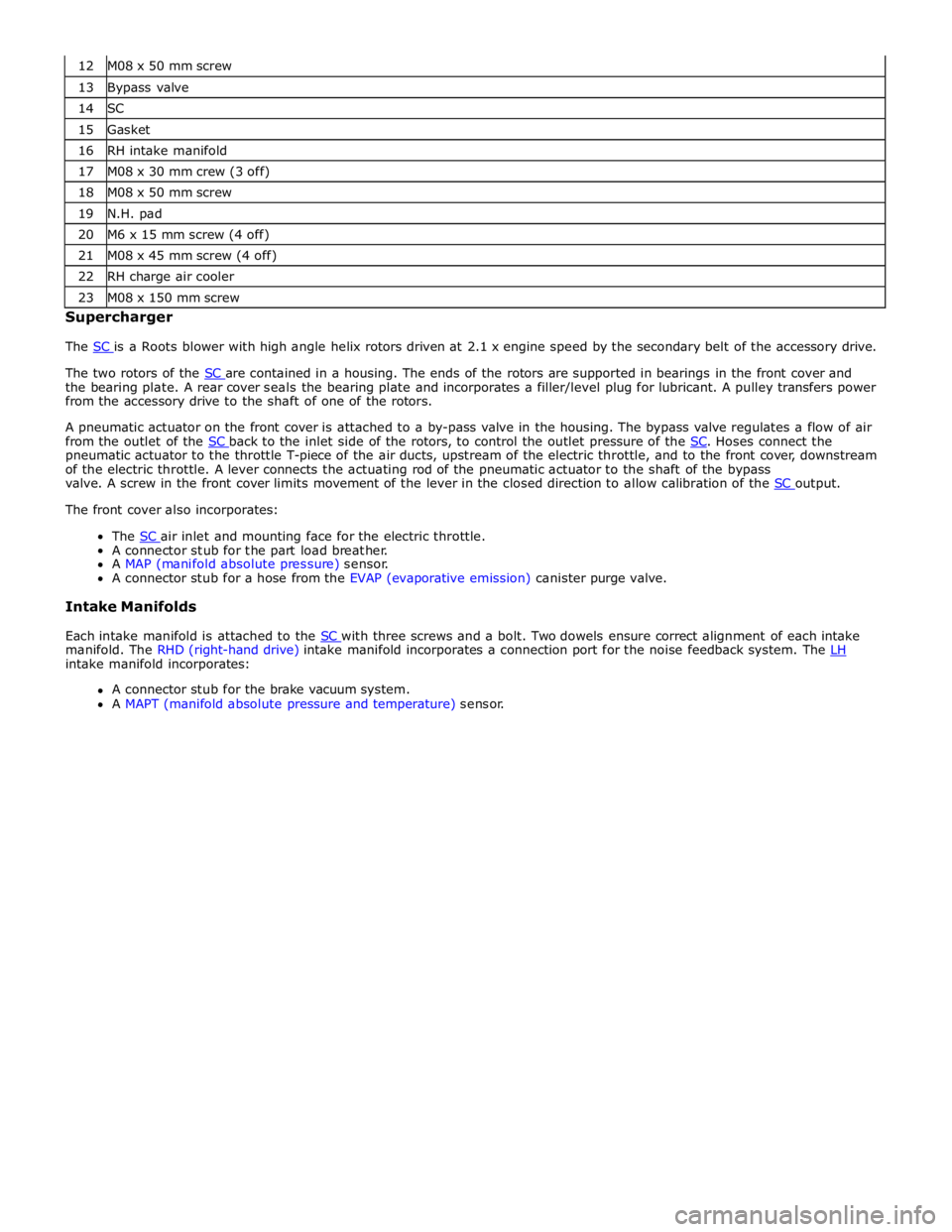
13 Bypass valve 14 SC 15 Gasket 16 RH intake manifold 17 M08 x 30 mm crew (3 off) 18 M08 x 50 mm screw 19 N.H. pad 20 M6 x 15 mm screw (4 off) 21 M08 x 45 mm screw (4 off) 22 RH charge air cooler 23 M08 x 150 mm screw Supercharger
The SC is a Roots blower with high angle helix rotors driven at 2.1 x engine speed by the secondary belt of the accessory drive.
The two rotors of the SC are contained in a housing. The ends of the rotors are supported in bearings in the front cover and the bearing plate. A rear cover seals the bearing plate and incorporates a filler/level plug for lubricant. A pulley transfers power
from the accessory drive to the shaft of one of the rotors.
A pneumatic actuator on the front cover is attached to a by-pass valve in the housing. The bypass valve regulates a flow of air
from the outlet of the SC back to the inlet side of the rotors, to control the outlet pressure of the SC. Hoses connect the pneumatic actuator to the throttle T-piece of the air ducts, upstream of the electric throttle, and to the front cover, downstream
of the electric throttle. A lever connects the actuating rod of the pneumatic actuator to the shaft of the bypass
valve. A screw in the front cover limits movement of the lever in the closed direction to allow calibration of the SC output. The front cover also incorporates:
The SC air inlet and mounting face for the electric throttle. A connector stub for the part load breather.
A MAP (manifold absolute pressure) sensor.
A connector stub for a hose from the EVAP (evaporative emission) canister purge valve.
Intake Manifolds
Each intake manifold is attached to the SC with three screws and a bolt. Two dowels ensure correct alignment of each intake manifold. The RHD (right-hand drive) intake manifold incorporates a connection port for the noise feedback system. The LH intake manifold incorporates:
A connector stub for the brake vacuum system.
A MAPT (manifold absolute pressure and temperature) sensor.
Page 1350 of 3039
Published: 11-May-2011
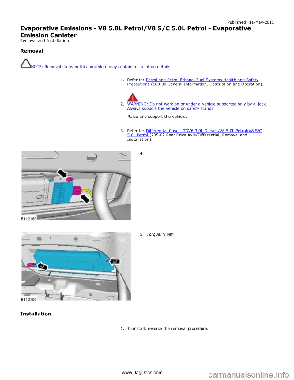
Evaporative Emissions - V8 5.0L Petrol/V8 S/C 5.0L Petrol - Evaporative
Emission Canister
Removal and Installation
Removal
NOTE: Removal steps in this procedure may contain installation details.
1. Refer to: Petrol and Petrol-Ethanol Fuel Systems Health and Safety Precautions (100-00 General Information, Description and Operation).
2. WARNING: Do not work on or under a vehicle supported only by a jack.
Always support the vehicle on safety stands.
Raise and support the vehicle.
3. Refer to: Differential Case - TDV6 3.0L Diesel /V8 5.0L Petrol/V8 S/C 5.0L Petrol (205-02 Rear Drive Axle/Differential, Removal and Installation).
Installation
4.
5. Torque: 9 Nm
1. To install, reverse the removal procedure. www.JagDocs.com
Page 1362 of 3039
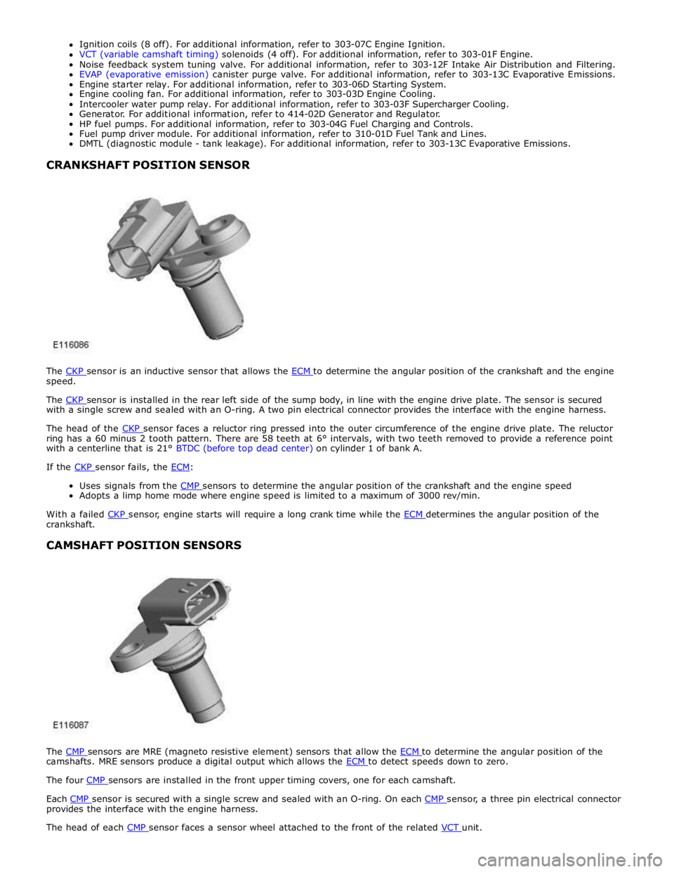
speed.
The CKP sensor is installed in the rear left side of the sump body, in line with the engine drive plate. The sensor is secured with a single screw and sealed with an O-ring. A two pin electrical connector provides the interface with the engine harness.
The head of the CKP sensor faces a reluctor ring pressed into the outer circumference of the engine drive plate. The reluctor ring has a 60 minus 2 tooth pattern. There are 58 teeth at 6° intervals, with two teeth removed to provide a reference point
with a centerline that is 21° BTDC (before top dead center) on cylinder 1 of bank A.
If the CKP sensor fails, the ECM:
Uses signals from the CMP sensors to determine the angular position of the crankshaft and the engine speed Adopts a limp home mode where engine speed is limited to a maximum of 3000 rev/min.
With a failed CKP sensor, engine starts will require a long crank time while the ECM determines the angular position of the crankshaft.
CAMSHAFT POSITION SENSORS
The CMP sensors are MRE (magneto resistive element) sensors that allow the ECM to determine the angular position of the camshafts. MRE sensors produce a digital output which allows the ECM to detect speeds down to zero. The four CMP sensors are installed in the front upper timing covers, one for each camshaft.
Each CMP sensor is secured with a single screw and sealed with an O-ring. On each CMP sensor, a three pin electrical connector provides the interface with the engine harness.
The head of each CMP sensor faces a sensor wheel attached to the front of the related VCT unit.
Page 1363 of 3039
Defaults to base mapping for the ignition timing, with no cylinder correction
Disables the VCT system.
ENGINE COOLANT TEMPERATURE SENSORS
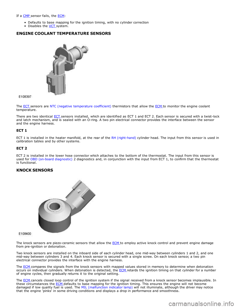
The ECT sensors are NTC (negative temperature coefficient) thermistors that allow the ECM to monitor the engine coolant temperature.
There are two identical ECT sensors installed, which are identified as ECT 1 and ECT 2. Each sensor is secured with a twist-lock and latch mechanism, and is sealed with an O-ring. A two pin electrical connector provides the interface between the sensor
and the engine harness.
ECT 1
ECT 1 is installed in the heater manifold, at the rear of the RH (right-hand) cylinder head. The input from this sensor is used in
calibration tables and by other systems.
ECT 2
ECT 2 is installed in the lower hose connector which attaches to the bottom of the thermostat. The input from this sensor is
used for OBD (on-board diagnostic) 2 diagnostics and, in conjunction with the input from ECT 1, to confirm that the thermostat
is functional.
KNOCK SENSORS
The knock sensors are piezo-ceramic sensors that allow the ECM to employ active knock control and prevent engine damage from pre-ignition or detonation.
Two knock sensors are installed on the inboard side of each cylinder head, one mid-way between cylinders 1 and 2, and one
mid-way between cylinders 3 and 4. Each knock sensor is secured with a single screw. On each knock sensor, a two pin
electrical connector provides the interface with the engine harness.
The ECM compares the signals from the knock sensors with mapped values stored in memory to determine when detonation occurs on individual cylinders. When detonation is detected, the ECM retards the ignition timing on that cylinder for a number of engine cycles, then gradually returns it to the original setting.
The ECM cancels closed loop control of the ignition system if the signal received from a knock sensor becomes implausible. In these circumstances the ECM defaults to base mapping for the ignition timing. This ensures the engine will not become damaged if low quality fuel is used. The MIL (malfunction indicator lamp) will not illuminate, although the driver may notice
that the engine 'pinks' in some driving conditions and displays a drop in performance and smoothness.
Page 1426 of 3039
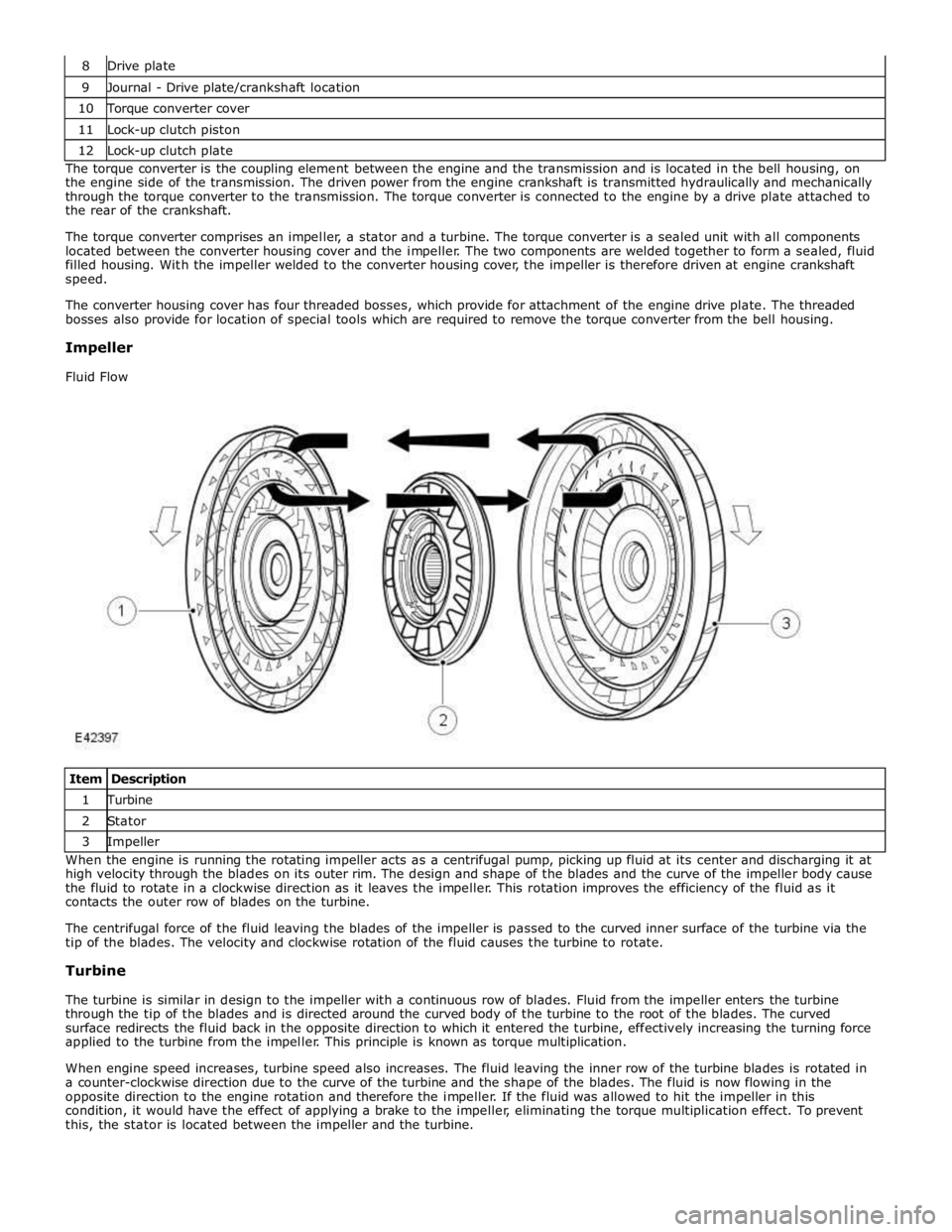
9 Journal - Drive plate/crankshaft location 10 Torque converter cover 11 Lock-up clutch piston 12 Lock-up clutch plate The torque converter is the coupling element between the engine and the transmission and is located in the bell housing, on
the engine side of the transmission. The driven power from the engine crankshaft is transmitted hydraulically and mechanically
through the torque converter to the transmission. The torque converter is connected to the engine by a drive plate attached to
the rear of the crankshaft.
The torque converter comprises an impeller, a stator and a turbine. The torque converter is a sealed unit with all components
located between the converter housing cover and the impeller. The two components are welded together to form a sealed, fluid
filled housing. With the impeller welded to the converter housing cover, the impeller is therefore driven at engine crankshaft
speed.
The converter housing cover has four threaded bosses, which provide for attachment of the engine drive plate. The threaded
bosses also provide for location of special tools which are required to remove the torque converter from the bell housing.
Impeller
Fluid Flow
Item Description 1 Turbine 2 Stator 3 Impeller When the engine is running the rotating impeller acts as a centrifugal pump, picking up fluid at its center and discharging it at
high velocity through the blades on its outer rim. The design and shape of the blades and the curve of the impeller body cause
the fluid to rotate in a clockwise direction as it leaves the impeller. This rotation improves the efficiency of the fluid as it
contacts the outer row of blades on the turbine.
The centrifugal force of the fluid leaving the blades of the impeller is passed to the curved inner surface of the turbine via the
tip of the blades. The velocity and clockwise rotation of the fluid causes the turbine to rotate.
Turbine
The turbine is similar in design to the impeller with a continuous row of blades. Fluid from the impeller enters the turbine
through the tip of the blades and is directed around the curved body of the turbine to the root of the blades. The curved
surface redirects the fluid back in the opposite direction to which it entered the turbine, effectively increasing the turning force
applied to the turbine from the impeller. This principle is known as torque multiplication.
When engine speed increases, turbine speed also increases. The fluid leaving the inner row of the turbine blades is rotated in
a counter-clockwise direction due to the curve of the turbine and the shape of the blades. The fluid is now flowing in the
opposite direction to the engine rotation and therefore the impeller. If the fluid was allowed to hit the impeller in this
condition, it would have the effect of applying a brake to the impeller, eliminating the torque multiplication effect. To prevent
this, the stator is located between the impeller and the turbine.
Page 1475 of 3039
15.
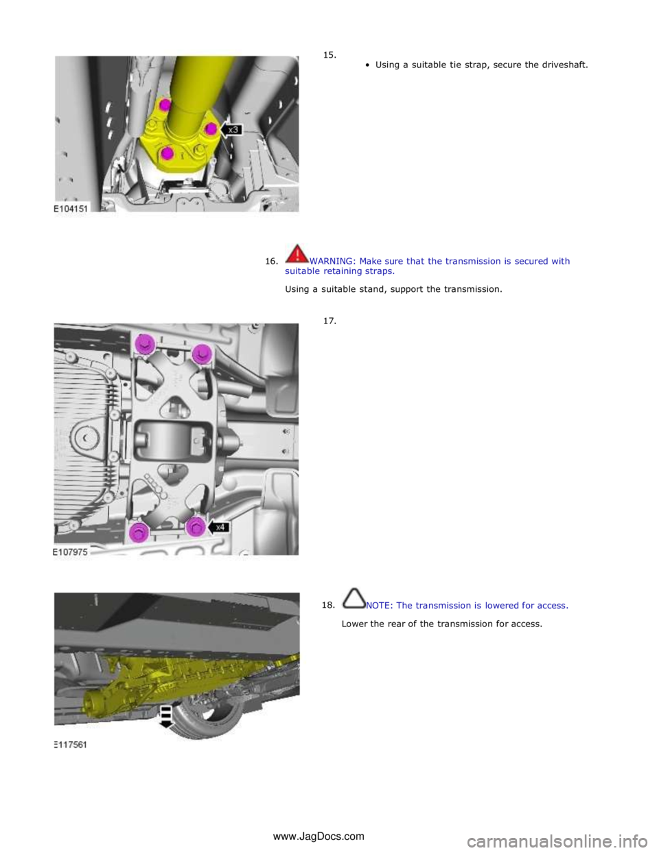
Using a suitable tie strap, secure the driveshaft.
16. WARNING: Make sure that the transmission is secured with
suitable retaining straps.
Using a suitable stand, support the transmission.
17.
18.
NOTE: The transmission is lowered for access.
Lower the rear of the transmission for access. www.JagDocs.com
Page 1492 of 3039
15.
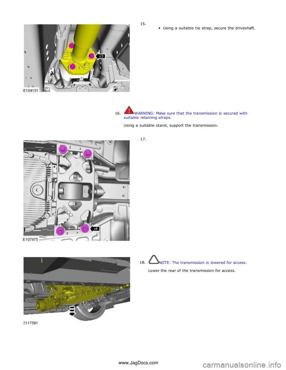
Using a suitable tie strap, secure the driveshaft.
16. WARNING: Make sure that the transmission is secured with
suitable retaining straps.
Using a suitable stand, support the transmission.
17.
18.
NOTE: The transmission is lowered for access.
Lower the rear of the transmission for access. www.JagDocs.com
Page 1550 of 3039
Published: 11-May-2011
Exhaust System - V8 5.0L Petrol/V8 S/C 5.0L Petrol - Catalytic Converter LH
Removal and Installation
Removal
NOTE: Removal steps in this procedure may contain installation details.
1. Refer to: Battery Disconnect and Connect (414-01 Battery, Mounting and Cables, General Procedures).
2. WARNINGS:
Make sure to support the vehicle with axle stands.
Observe due care when working near a hot exhaust system.
Raise and support the vehicle.
3. Refer to: Air Deflector (501-02 Front End Body Panels, Removal and Installation).
4. Refer to: Engine Rear Undershield (501-02 Front End Body Panels, Removal and Installation).
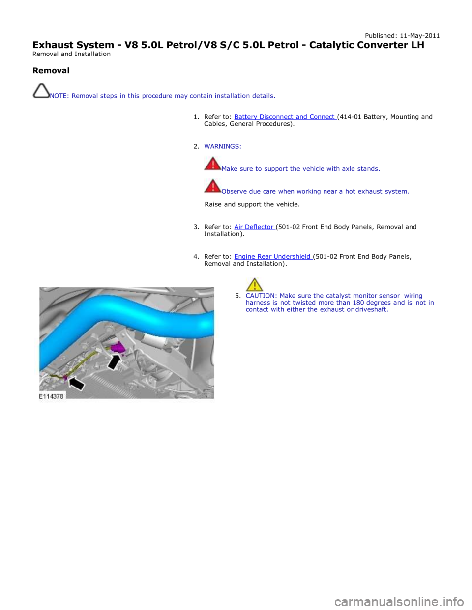
5. CAUTION: Make sure the catalyst monitor sensor wiring
harness is not twisted more than 180 degrees and is not in
contact with either the exhaust or driveshaft.