2010 INFINITI QX56 Oil
[x] Cancel search: OilPage 1947 of 4210
EM-96
< DISASSEMBLY AND ASSEMBLY >
ENGINE UNIT
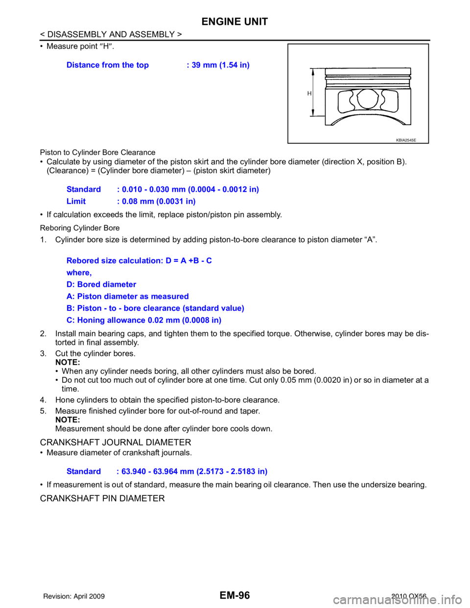
• Measure point ″H″.
Piston to Cylinde r Bore Clearance
• Calculate by using diameter of the piston skirt and the cylinder bore diameter (direction X, position B).
(Clearance) = (Cylinder bore diameter) – (piston skirt diameter)
• If calculation exceeds the limit, replace piston/piston pin assembly.
Reboring Cylinder Bore
1. Cylinder bore size is determined by adding pi ston-to-bore clearance to piston diameter “A”.
2. Install main bearing caps, and tighten them to the specified torque. Otherwise, cylinder bores may be dis-
torted in final assembly.
3. Cut the cylinder bores. NOTE:
• When any cylinder needs boring, all other cylinders must also be bored.
• Do not cut too much out of cylinder bore at one time. Cut only 0.05 mm (0.0020 in) or so in diameter at atime.
4. Hone cylinders to obtain the specified piston-to-bore clearance.
5. Measure finished cylinder bore for out-of-round and taper. NOTE:
Measurement should be done after cylinder bore cools down.
CRANKSHAFT JOURNAL DIAMETER
• Measure diameter of crankshaft journals.
• If measurement is out of standard, measure the main bearing oil clearance. Then use the undersize bearing.
CRANKSHAFT PIN DIAMETER
Distance from the top : 39 mm (1.54 in)
KBIA2545E
Standard : 0.010 - 0.030 mm (0.0004 - 0.0012 in)
Limit : 0.08 mm (0.0031 in)
Rebored size calculation: D = A +B - C
where,
D: Bored diameter
A: Piston diameter as measured
B: Piston - to - bore clearance (standard value)
C: Honing allowance 0.02 mm (0.0008 in)
Standard : 63.940 - 63.964 mm (2.5173 - 2.5183 in)
Revision: April 20092010 QX56
Page 1948 of 4210
ENGINE UNITEM-97
< DISASSEMBLY AND ASSEMBLY >
C
DE
F
G H
I
J
K L
M A
EM
NP
O
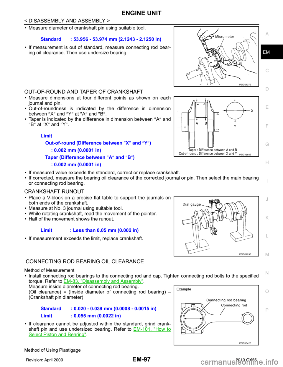
• Measure diameter of crankshaft pin using suitable tool.
• If measurement is out of standard, measure connecting rod bear-
ing oil clearance. Then use undersize bearing.
OUT-OF-ROUND AND TAPER OF CRANKSHAFT
• Measure dimensions at four di fferent points as shown on each
journal and pin.
• Out-of-roundness is indicated by the difference in dimension
between ″X″ and ″Y″ at ″A″ and ″B″ .
• Taper is indicated by the difference in dimension between ″A ″ and
″ B″ at ″X ″ and ″Y″ .
• If measured value exceeds the standard, correct or replace crankshaft.
• If corrected, measure the bearing oil clearance of the corrected journal or pin. Then select the main bearing or connecting rod bearing.
CRANKSHAFT RUNOUT
• Place a V-block on a precise flat table to support the journals onboth ends of the crankshaft.
• Measure at No. 3 journal using suitable tool.
• While rotating crankshaft, read the movement of the pointer.
• Half of the movement shows the runout.
• If measurement exceeds the limit, replace crankshaft.
CONNECTING ROD BEARING OIL CLEARANCE
Method of Measurement
• Install connecting rod bearings to the connecting rod and cap. Tighten connecting rod bolts to the specified
torque. Refer to EM-83, "
Disassembly and Assembly".
Measure inside diameter of connecting rod bearing.
(Oil clearance) = (Inside diameter of connecting rod bearing) –
(Crankshaft pin diameter)
• If clearance cannot be adjusted wit hin the standard, grind crank-
shaft pin and use undersized bearing. Refer to EM-101, "
How to
Select Piston and Bearing".
Method of Using Plastigage
Standard : 53.956 - 53.974 mm (2.1243 - 2.1250 in)
PBIC0127E
Limit
Out-of-round (Difference between ″X ″ and ″ Y″)
: 0.002 mm (0.0001 in)
Taper (Difference between ″ A″ and ″B ″)
: 0.002 mm (0.0001 in)
PBIC1685E
Limit : Less than 0.05 mm (0.002 in)
PBIC0129E
Standard : 0.020 - 0.039 mm (0.0008 - 0.0015 in)
Limit : 0.055 mm (0.0022 in)
PBIC1642E
Revision: April 20092010 QX56
Page 1949 of 4210
EM-98
< DISASSEMBLY AND ASSEMBLY >
ENGINE UNIT
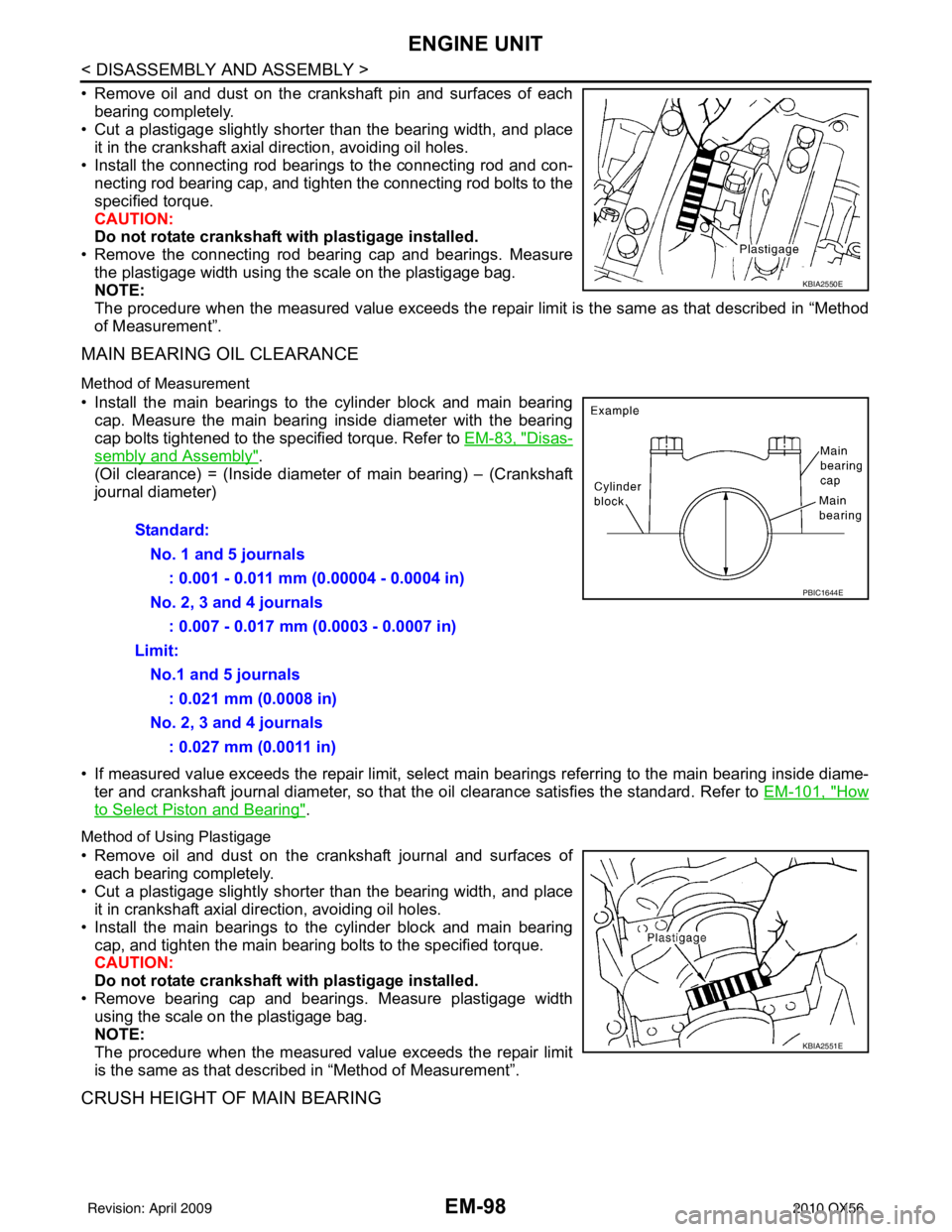
• Remove oil and dust on the crankshaft pin and surfaces of eachbearing completely.
• Cut a plastigage slightly shorter than the bearing width, and place
it in the crankshaft axial direction, avoiding oil holes.
• Install the connecting rod beari ngs to the connecting rod and con-
necting rod bearing cap, and tighten the connecting rod bolts to the
specified torque.
CAUTION:
Do not rotate crankshaft with plastigage installed.
• Remove the connecting rod bear ing cap and bearings. Measure
the plastigage width using the scale on the plastigage bag.
NOTE:
The procedure when the measured value exceeds the repair limit is the same as that described in “Method
of Measurement”.
MAIN BEARING OIL CLEARANCE
Method of Measurement
• Install the main bearings to the cylinder block and main bearing cap. Measure the main bearing inside diameter with the bearing
cap bolts tightened to the specified torque. Refer to EM-83, "
Disas-
sembly and Assembly".
(Oil clearance) = (Inside diameter of main bearing) – (Crankshaft
journal diameter)
• If measured value exceeds the repair limit, select main bearings referring to the main bearing inside diame-
ter and crankshaft journal diameter, so that the oil clearance satisfies the standard. Refer to EM-101, "
How
to Select Piston and Bearing".
Method of Using Plastigage
• Remove oil and dust on the crankshaft journal and surfaces of
each bearing completely.
• Cut a plastigage slightly shorter than the bearing width, and place it in crankshaft axial direction, avoiding oil holes.
• Install the main bearings to the cylinder block and main bearing cap, and tighten the main bearing bolts to the specified torque.
CAUTION:
Do not rotate crankshaft with plastigage installed.
• Remove bearing cap and bearings. Measure plastigage width using the scale on the plastigage bag.
NOTE:
The procedure when the measured value exceeds the repair limit
is the same as that descri bed in “Method of Measurement”.
CRUSH HEIGHT OF MAIN BEARING
KBIA2550E
Standard:
No. 1 and 5 journals : 0.001 - 0.011 mm (0.00004 - 0.0004 in)
No. 2, 3 and 4 journals : 0.007 - 0.017 mm (0.0003 - 0.0007 in)
Limit: No.1 and 5 journals : 0.021 mm (0.0008 in)
No. 2, 3 and 4 journals : 0.027 mm (0.0011 in)
PBIC1644E
KBIA2551E
Revision: April 20092010 QX56
Page 1954 of 4210
HOW TO SELECT PISTON AND BEARINGEM-103
< DISASSEMBLY AND ASSEMBLY >
C
DE
F
G H
I
J
K L
M A
EM
NP
O
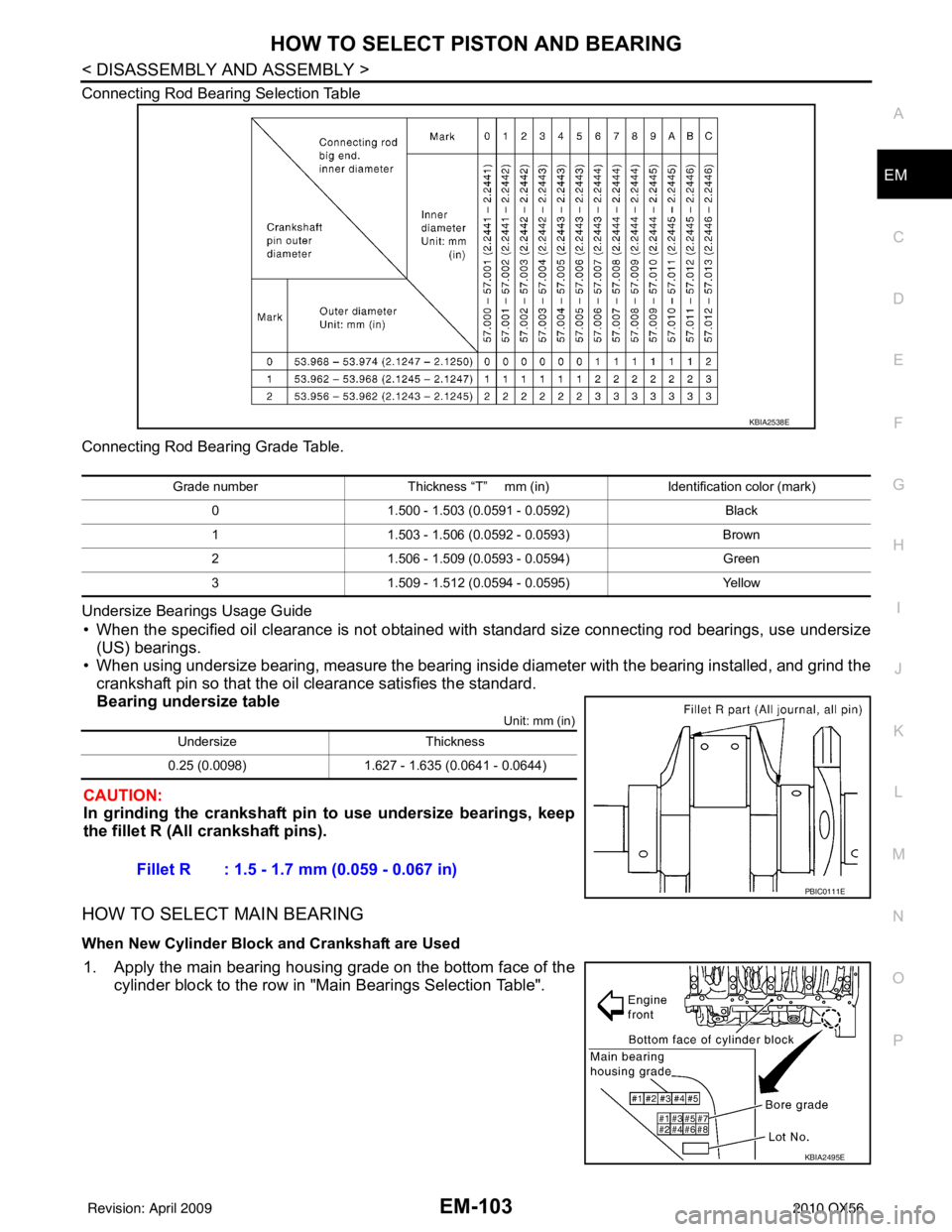
Connecting Rod Bearing Selection Table
Connecting Rod Bearing Grade Table.
Undersize Bearings Usage Guide
• When the specified oil clearance is not obtained with standard size connecting rod bearings, use undersize
(US) bearings.
• When using undersize bearing, measure the bearing inside diameter with the bearing installed, and grind the
crankshaft pin so that the oil clearance satisfies the standard.
Bearing undersize table
Unit: mm (in)
CAUTION:
In grinding the crankshaft pin to use undersize bearings, keep
the fillet R (All crankshaft pins).
HOW TO SELECT MAIN BEARING
When New Cylinder Block and Crankshaft are Used
1. Apply the main bearing housing grade on the bottom face of the cylinder block to the row in "Main Bearings Selection Table".
KBIA2538E
Grade number Thickness “T” mm (in) Identification color (mark)
0 1.500 - 1.503 (0.0591 - 0.0592) Black
1 1.503 - 1.506 (0.0592 - 0.0593) Brown
2 1.506 - 1.509 (0.0593 - 0.0594) Green
3 1.509 - 1.512 (0.0594 - 0.0595) Yellow
UndersizeThickness
0.25 (0.0098) 1.627 - 1.635 (0.0641 - 0.0644)
Fillet R : 1.5 - 1.7 mm (0.059 - 0.067 in)
PBIC0111E
KBIA2495E
Revision: April 20092010 QX56
Page 1958 of 4210
HOW TO SELECT PISTON AND BEARINGEM-107
< DISASSEMBLY AND ASSEMBLY >
C
DE
F
G H
I
J
K L
M A
EM
NP
O
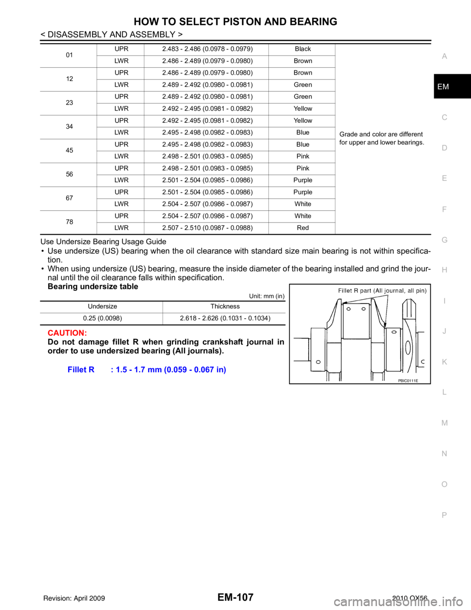
Use Undersize Bearing Usage Guide
• Use undersize (US) bearing when the oil clearance with
standard size main bearing is not within specifica-
tion.
• When using undersize (US) bearing, measure the inside di ameter of the bearing installed and grind the jour-
nal until the oil clearance falls within specification.
Bearing undersize table
Unit: mm (in)
CAUTION:
Do not damage fillet R when grinding crankshaft journal in
order to use undersized bearing (All journals).
01 UPR
2.483 - 2.486 (0.0978 - 0.0979) Black
Grade and color are different
for upper and lower bearings.
LWR
2.486 - 2.489 (0.0979 - 0.0980) Brown
12 UPR
2.486 - 2.489 (0.0979 - 0.0980) Brown
LWR 2.489 - 2.492 (0.0980 - 0.0981) Green
23 UPR
2.489 - 2.492 (0.0980 - 0.0981) Green
LWR 2.492 - 2.495 (0.0981 - 0.0982) Yellow
34 UPR
2.492 - 2.495 (0.0981 - 0.0982) Yellow
LWR 2.495 - 2.498 (0.0982 - 0.0983) Blue
45 UPR
2.495 - 2.498 (0.0982 - 0.0983) Blue
LWR 2.498 - 2.501 (0.0983 - 0.0985) Pink
56 UPR
2.498 - 2.501 (0.0983 - 0.0985) Pink
LWR 2.501 - 2.504 (0.0985 - 0.0986) Purple
67 UPR
2.501 - 2.504 (0.0985 - 0.0986) Purple
LWR 2.504 - 2.507 (0.0986 - 0.0987) White
78 UPR
2.504 - 2.507 (0.0986 - 0.0987) White
LWR 2.507 - 2.510 (0.0987 - 0.0988) Red
UndersizeThickness
0.25 (0.0098) 2.618 - 2.626 (0.1031 - 0.1034)
Fillet R : 1.5 - 1.7 mm (0.059 - 0.067 in)
PBIC0111E
Revision: April 20092010 QX56
Page 1959 of 4210
EM-108
< SERVICE DATA AND SPECIFICATIONS (SDS)
SERVICE DATA AND SPECIFICATIONS (SDS)
SERVICE DATA AND SPECIFICATIONS (SDS)
SERVICE DATA AND SPECIFICATIONS (SDS)
Standard and LimitINFOID:0000000005149018
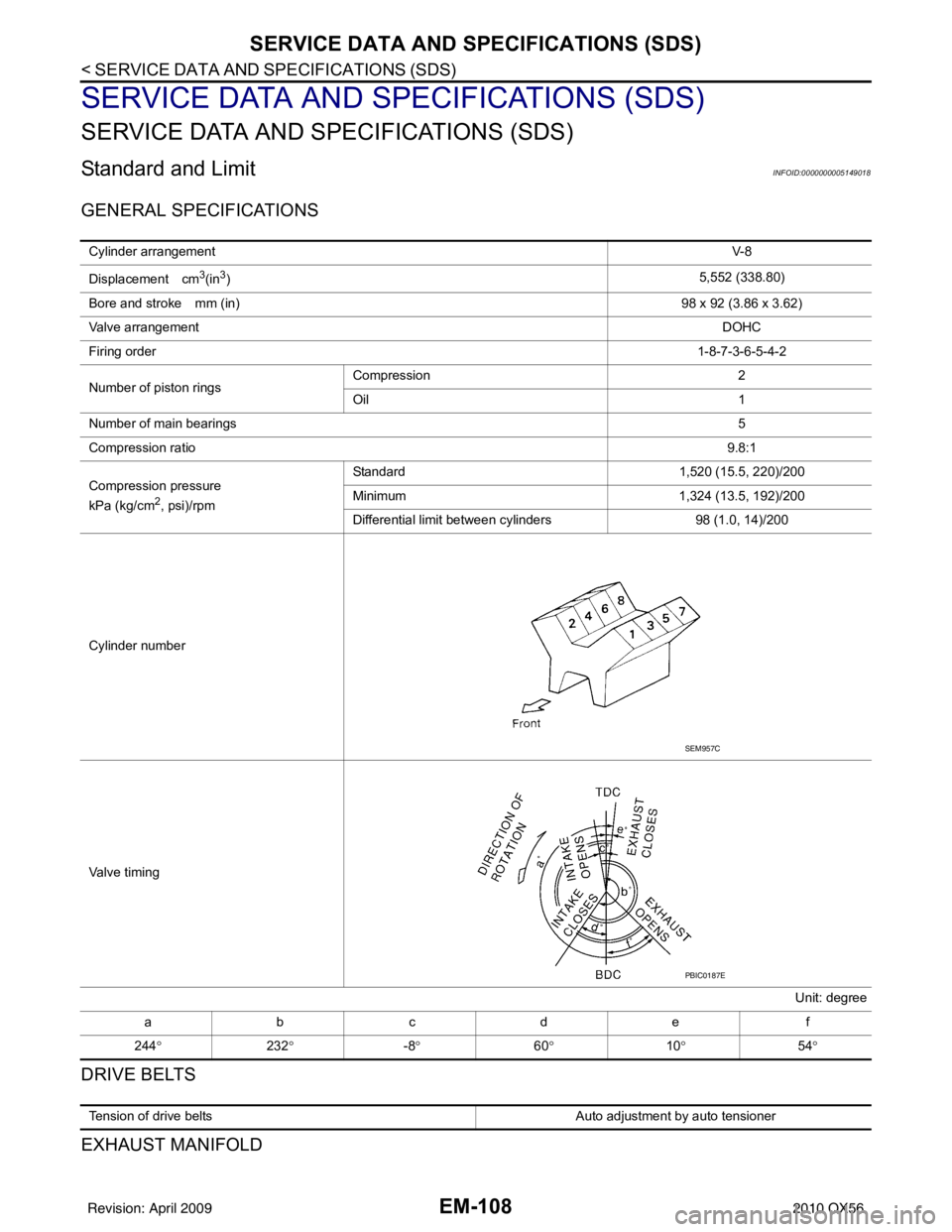
GENERAL SPECIFICATIONS
DRIVE BELTS
EXHAUST MANIFOLD
Cylinder arrangementV- 8
Displacement cm
3(in3) 5,552 (338.80)
Bore and stroke mm (in) 98 x 92 (3.86 x 3.62)
Valve arrangement DOHC
Firing order 1-8-7-3-6-5-4-2
Number of piston rings Compression
2
Oil 1
Number of main bearings 5
Compression ratio 9.8:1
Compression pressure
kPa (kg/cm
2, psi)/rpm Standard 1,520 (15.5, 220)/200
Minimum
1,324 (13.5, 192)/200
Differential limit between cylinders 98 (1.0, 14)/200
Cylinder number
Valve timing Unit: degree
abcde f
244 ° 232° -8° 60° 10° 54°
SEM957C
PBIC0187E
Tension of drive belts Auto adjustment by auto tensioner
Revision: April 20092010 QX56
Page 1965 of 4210
EM-114
< SERVICE DATA AND SPECIFICATIONS (SDS)
SERVICE DATA AND SPECIFICATIONS (SDS)
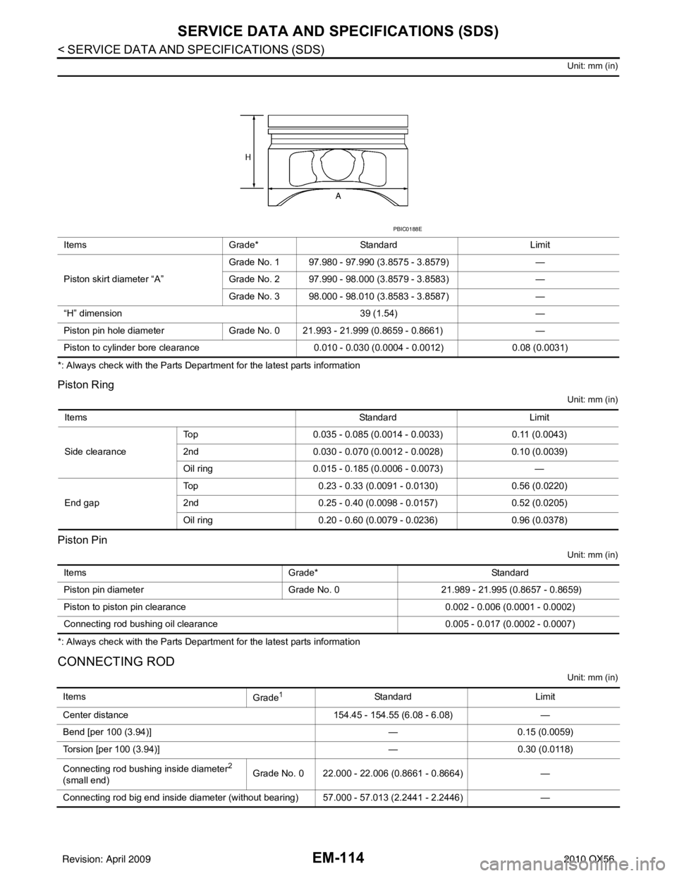
Unit: mm (in)
*: Always check with the Parts Department for the latest parts information
Piston Ring
Unit: mm (in)
Piston Pin
Unit: mm (in)
*: Always check with the Parts Department for the latest parts information
CONNECTING ROD
Unit: mm (in)
ItemsGrade*Standard Limit
Piston skirt diameter “A” Grade No. 1 97.980 - 97.990 (3.8575 - 3.8579)
—
Grade No. 2 97.990 - 98.000 (3.8579 - 3.8583) —
Grade No. 3 98.000 - 98.010 (3.8583 - 3.8587) —
“H” dimension 39 (1.54)—
Piston pin hole diameter Grade No. 0 21.993 - 21.999 (0.8659 - 0.8661) —
Piston to cylinder bore clearance 0.010 - 0.030 (0.0004 - 0.0012)0.08 (0.0031)
PBIC0188E
Items StandardLimit
Side clearance Top
0.035 - 0.085 (0.0014 - 0.0033) 0.11 (0.0043)
2nd 0.030 - 0.070 (0.0012 - 0.0028) 0.10 (0.0039)
Oil ring 0.015 - 0.185 (0.0006 - 0.0073) —
End gap Top
0.23 - 0.33 (0.0091 - 0.0130) 0.56 (0.0220)
2nd 0.25 - 0.40 (0.0098 - 0.0157) 0.52 (0.0205)
Oil ring 0.20 - 0.60 (0.0079 - 0.0236) 0.96 (0.0378)
Items Grade*Standard
Piston pin diameter Grade No. 0 21.989 - 21.995 (0.8657 - 0.8659)
Piston to piston pin clearance 0.002 - 0.006 (0.0001 - 0.0002)
Connecting rod bushing oil clearance 0.005 - 0.017 (0.0002 - 0.0007)
Items
Grade1StandardLimit
Center distance 154.45 - 154.55 (6.08 - 6.08)—
Bend [per 100 (3.94)] —0.15 (0.0059)
Torsion [per 100 (3.94)] —0.30 (0.0118)
Connecting rod bushing inside diameter
2
(small end) Grade No. 0 22.000 - 22.006 (0.8661 - 0.8664)
—
Connecting rod big end inside diameter (without bearing) 57.000 - 57.013 (2.2441 - 2.2446) —
Revision: April 20092010 QX56
Page 1968 of 4210
SERVICE DATA AND SPECIFICATIONS (SDS)EM-117
< SERVICE DATA AND SPECIFICATIONS (SDS)
C
DE
F
G H
I
J
K L
M A
EM
NP
O
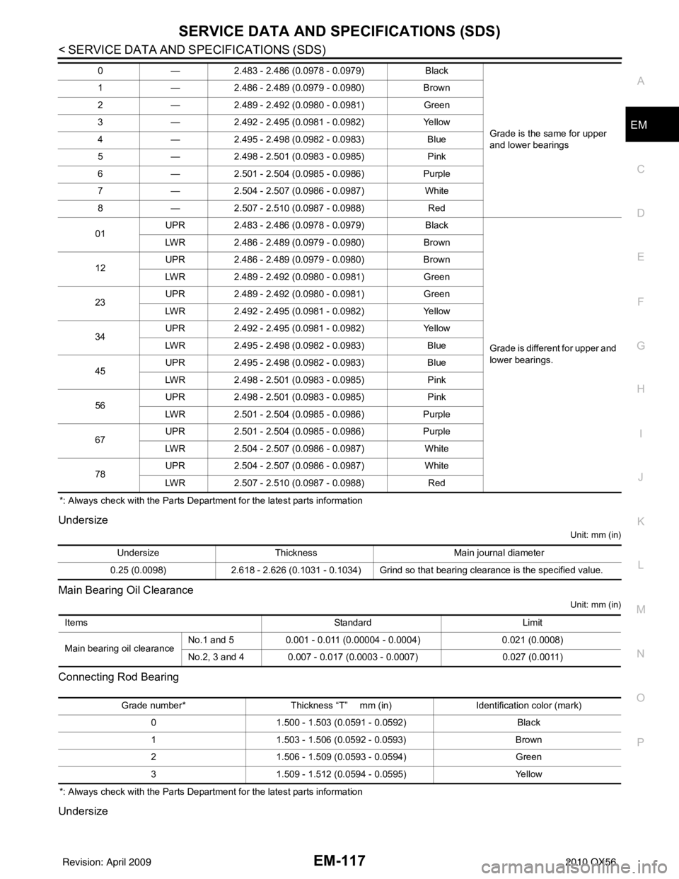
*: Always check with the Parts Department for the latest parts information
Undersize
Unit: mm (in)
Main Bearing Oil Clearance
Unit: mm (in)
Connecting Rod Bearing
*: Always check with the Parts Department for the latest parts information
Undersize
0
—2.483 - 2.486 (0.0978 - 0.0979) Black
Grade is the same for upper
and lower bearings
1
—2.486 - 2.489 (0.0979 - 0.0980) Brown
2 —2.489 - 2.492 (0.0980 - 0.0981) Green
3 —2.492 - 2.495 (0.0981 - 0.0982) Yellow
4 —2.495 - 2.498 (0.0982 - 0.0983) Blue
5 —2.498 - 2.501 (0.0983 - 0.0985) Pink
6 —2.501 - 2.504 (0.0985 - 0.0986) Purple
7 —2.504 - 2.507 (0.0986 - 0.0987) White
8 —2.507 - 2.510 (0.0987 - 0.0988) Red
01 UPR
2.483 - 2.486 (0.0978 - 0.0979) Black
Grade is different for upper and
lower bearings.
LWR
2.486 - 2.489 (0.0979 - 0.0980) Brown
12 UPR
2.486 - 2.489 (0.0979 - 0.0980) Brown
LWR 2.489 - 2.492 (0.0980 - 0.0981) Green
23 UPR
2.489 - 2.492 (0.0980 - 0.0981) Green
LWR 2.492 - 2.495 (0.0981 - 0.0982) Yellow
34 UPR
2.492 - 2.495 (0.0981 - 0.0982) Yellow
LWR 2.495 - 2.498 (0.0982 - 0.0983) Blue
45 UPR
2.495 - 2.498 (0.0982 - 0.0983) Blue
LWR 2.498 - 2.501 (0.0983 - 0.0985) Pink
56 UPR
2.498 - 2.501 (0.0983 - 0.0985) Pink
LWR 2.501 - 2.504 (0.0985 - 0.0986) Purple
67 UPR
2.501 - 2.504 (0.0985 - 0.0986) Purple
LWR 2.504 - 2.507 (0.0986 - 0.0987) White
78 UPR
2.504 - 2.507 (0.0986 - 0.0987) White
LWR 2.507 - 2.510 (0.0987 - 0.0988) Red
UndersizeThickness Main journal diameter
0.25 (0.0098) 2.618 - 2.626 (0.1031 - 0.1034) Grind so that bearing clearance is the specified value.
Items StandardLimit
Main bearing oil clearance No.1 and 5
0.001 - 0.011 (0.00004 - 0.0004) 0.021 (0.0008)
No.2, 3 and 4 0.007 - 0.017 (0.0003 - 0.0007) 0.027 (0.0011)
Grade number*Thickness “T” mm (in) Identification color (mark)
0 1.500 - 1.503 (0.0591 - 0.0592) Black
1 1.503 - 1.506 (0.0592 - 0.0593) Brown
2 1.506 - 1.509 (0.0593 - 0.0594) Green
3 1.509 - 1.512 (0.0594 - 0.0595) Yellow
Revision: April 20092010 QX56