2010 INFINITI QX56 Oil
[x] Cancel search: OilPage 2136 of 4210
EXT-1
BODY EXTERIOR, DOORS, ROOF & VEHICLE SECURITY
C
DE
F
G H
I
J
L
M
SECTION EXT
A
B
EXT
N
O P
CONTENTS
EXTERIOR
SERVICE INFORMATION .. ..........................2
PRECAUTIONS .............................................. .....2
Precaution for Supplemental Restraint System
(SRS) "AIR BAG" and "SEAT BELT PRE-TEN-
SIONER" ............................................................. ......
2
Precaution Necessary for Steering Wheel Rota-
tion After Battery Disconnect ............................... ......
2
Service Notice ...........................................................3
PREPARATION ...................................................4
Special Service Tool ........................................... ......4
Commercial Service Tool ..........................................4
SQUEAK AND RATTLE TROUBLE DIAG-
NOSES ................................................................
5
Work Flow ........................................................... ......5
Generic Squeak and Rattle Troubleshooting ............7
Diagnostic Worksheet ...............................................9
CLIP AND FASTENER .......................................11
Description .......................................................... ....11
FRONT BUMPER ...............................................13
Removal and Installation .........................................13
REAR BUMPER ............................................. ....15
Removal and Installation .........................................15
FRONT GRILLE .................................................17
Removal and Installation ..................................... ....17
COWL TOP .......................................................18
Removal and Installation .........................................18
FRONT FENDER ...............................................20
Removal and Installation .........................................20
OVER FENDER .................................................21
Removal and Installation .........................................21
FENDER PROTECTOR ....................................23
Removal and Installation .........................................23
LICENSE LAMP FINISHER ..............................24
Removal and Installation .........................................24
RUNNING BOARDS .........................................25
Removal and Installation .........................................25
REAR SPOILER ................................................26
Removal and Installation .........................................26
ROOF RACK .....................................................27
Removal and Installation ..................................... ....27
DOOR OUTSIDE MOLDING .............................28
Removal and Installation .........................................28
SIDE GUARD MOLDING ..................................30
Removal and Installation ..................................... ....30
Revision: April 20092010 QX56
Page 2138 of 4210
PRECAUTIONSEXT-3
< SERVICE INFORMATION >
C
DE
F
G H
I
J
L
M A
B
EXT
N
O P
5. When the repair work is completed, return the ignition switch to the ″LOCK ″ position before connecting
the battery cables. (At this time, the steering lock mechanism will engage.)
6. Perform a self-diagnosis check of al l control units using CONSULT-III.
Service NoticeINFOID:0000000005147311
• When removing or installing various parts, place a cloth or padding on the vehicle body to prevent scratches.
• Handle trim, molding, instruments, grille, etc. carefully during removing or installing. Be careful not to soil or
damage them.
• Apply sealing compound where necessary when installing parts.
• When applying sealing compound, be careful that the sealing compound does not protrude from parts.
• When replacing any metal parts (for example body outer panel, members, etc.), be sure to take rust preven-
tion measures.
Revision: April 20092010 QX56
Page 2161 of 4210
EXT-26
< SERVICE INFORMATION >
REAR SPOILER
REAR SPOILER
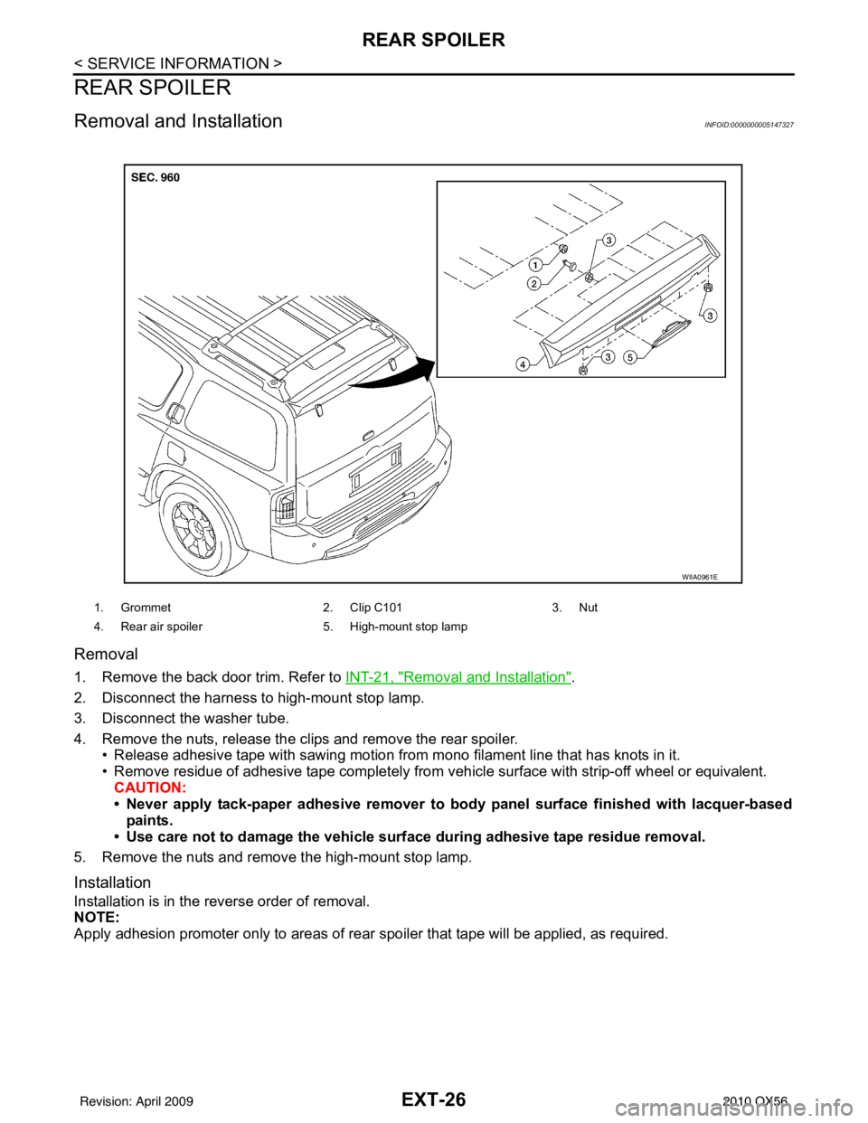
Removal and InstallationINFOID:0000000005147327
Removal
1. Remove the back door trim. Refer to INT-21, "Removal and Installation".
2. Disconnect the harness to high-mount stop lamp.
3. Disconnect the washer tube.
4. Remove the nuts, release the clips and remove the rear spoiler. • Release adhesive tape with sawing motion from mono filament line that has knots in it.
• Remove residue of adhesive tape completely from v ehicle surface with strip-off wheel or equivalent.
CAUTION:
• Never apply tack-paper adhesive remover to bo dy panel surface finished with lacquer-based
paints.
• Use care not to damage the vehicle surf ace during adhesive tape residue removal.
5. Remove the nuts and remove the high-mount stop lamp.
Installation
Installation is in the reverse order of removal.
NOTE:
Apply adhesion promoter only to areas of rear spoiler that tape will be applied, as required.
1. Grommet2. Clip C1013. Nut
4. Rear air spoiler 5. High-mount stop lamp
WIIA0961E
Revision: April 20092010 QX56
Page 2175 of 4210
DRIVE SHAFTFAX-9
< REMOVAL AND INSTALLATION >
CEF
G H
I
J
K L
M A
B
FA X
N
O P
DRIVE SHAFT
Removal and InstallationINFOID:0000000005148945
REMOVAL
1. Remove wheel and tire using power tool.
2. Remove engine under cover using power tool.
3. Remove wheel sensor harness from mount on knuckle and reposition aside. Refer to BRC-114, "
Removal
and Installation".
CAUTION:
Do not pull on wheel sensor harness.
4. Without disassembling the hydraulic lines, remove brake caliper using power tool. Reposition it aside with wire. Refer to BR-31, "
Removal and Installation of Brake Caliper and Rotor" .
NOTE:
Avoid depressing brake pedal while brake caliper is removed.
5. Remove coil spring and shock absorber assembly using power tool. Refer to FSU-14, "
Removal and
Installation" .
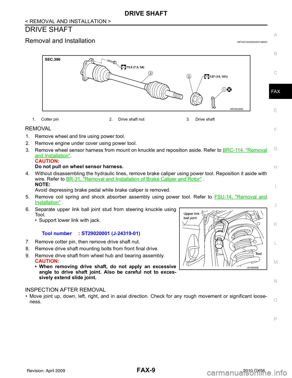
6. Separate upper link ball joint stud from steering knuckle using Tool.
• Support lower link with jack.
7. Remove cotter pin, then remove drive shaft nut.
8. Remove drive shaft mounting bolts from front final drive.
9. Remove drive shaft from wheel hub and bearing assembly. CAUTION:
• When removing drive shaf t, do not apply an excessive
angle to drive shaft joint. Also be careful not to exces-
sively extend slide joint.
INSPECTION AFTER REMOVAL
• Move joint up, down, left, right, and in axial directi on. Check for any rough movement or significant loose-
ness.
1. Cotter pin 2. Drive shaft nut3. Drive shaft
WDIA0329E
Tool number : ST29020001 (J-24319-01)
LEIA0095E
Revision: April 20092010 QX56
Page 2200 of 4210
FSU-1
SUSPENSION
C
DF
G H
I
J
K L
M
SECTION FSU
A
B
FSU
N
O PCONTENTS
FRONT SUSPENSION
PRECAUTION ....... ........................................2
PRECAUTIONS .............................................. .....2
Precaution for Supplemental Restraint System
(SRS) "AIR BAG" and "SEAT BELT PRE-TEN-
SIONER" ............................................................. ......
2
Precaution Necessary for Steering Wheel Rota-
tion After Battery Disconnect ............................... ......
2
Precaution .................................................................3
PREPARATION ............................................4
PREPARATION .............................................. .....4
Special Service Tool ........................................... ......4
Commercial Service Tool ..........................................4
SYMPTOM DIAGNOSIS ...............................5
NOISE, VIBRATION AND HARSHNESS
(NVH) TROUBLESHOOTING ........................ .....
5
NVH Troubleshooting Chart ................................ ......5
ON-VEHICLE MAINTENANCE .....................6
ON-VEHICLE SERVICE ................................. .....6
Front Suspension Parts ....................................... ......6
Front Wheel Alignment ..............................................6
UPPER BALL JOINT AND LOWER BALL
JOINT .................................................................
10
Inspection ............................................................ ....10
KNUCKLE ...................................................... ....12
On-Vehicle Inspection and Service ..................... ....12
ON-VEHICLE REPAIR .................................13
FRONT SUSPENSION ASSEMBLY .............. ....13
Component .......................................................... ....13
REMOVAL AND INSTALLATION ...............14
COIL SPRING AND SHOCK ABSORBER .......14
Removal and Installation ..................................... ....14
Disposal ...................................................................14
STABILIZER BAR .............................................15
Removal and Installation .........................................15
UPPER LINK .....................................................16
Removal and Installation ..................................... ....16
LOWER LINK ....................................................17
Removal and Installation .........................................17
UPPER BALL JOINT AND LOWER BALL
JOINT ................................................................
18
Removal and Installation .........................................18
KNUCKLE .........................................................19
Removal and Installation ..................................... ....19
DISASSEMBLY AND ASSEMBLY ..............21
COIL SPRING AND SHOCK ABSORBER .......21
Disassembly and Assembly ................................. ....21
SERVICE DATA AND SPECIFICATIONS
(SDS) ............... .......................................... ...
23
SERVICE DATA AND SPECIFICATIONS
(SDS) .................................................................
23
General Specification .......................................... ....23
Spring Free Height ..................................................23
Wheel Alignment (Unladen*1) ..................................23
Ball Joint .............................................................. ....24
Wheelarch Height (Unladen*1) ................................24
Revision: April 20092010 QX56
Page 2202 of 4210
PRECAUTIONSFSU-3
< PRECAUTION >
C
DF
G H
I
J
K L
M A
B
FSU
N
O P
5. When the repair work is completed, return the ignition switch to the ″LOCK ″ position before connecting
the battery cables. (At this time, the steering lock mechanism will engage.)
6. Perform a self-diagnosis check of al l control units using CONSULT-III.
PrecautionINFOID:0000000005148104
• When installing the rubber bushings, the final tightening must be done under unladen condition and with the
tires on level ground. Oil will shorten the life of the rubber bushings, so wipe off any spilled oil immediately.
• Unladen condition means the fuel tank, engine coolant and lubricants are at the full specification. The spare
tire, jack, hand tools, and mats are in their designated positions.
• After installing suspension components, check the wheel alignment.
• Lock nuts are not reusable. Always use new lock nuts for installation. New lock nuts are pre-oiled, do not
apply any additional lubrication.
Revision: April 20092010 QX56
Page 2203 of 4210
FSU-4
< PREPARATION >
PREPARATION
PREPARATION
PREPARATION
Special Service ToolINFOID:0000000005148105
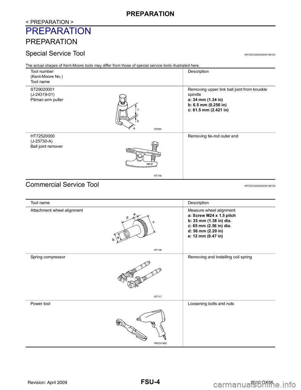
The actual shapes of Kent-Moore tools may differ from those of special service tools illustrated here.
Commercial Service ToolINFOID:0000000005148106
Tool number
(Kent-Moore No.)
Tool name Description
ST29020001
(J-24319-01)
Pitman arm puller Removing upper link ball joint from knuckle
spindle
a: 34 mm (1.34 in)
b: 6.5 mm (0.256 in)
c: 61.5 mm (2.421 in)
HT72520000
(J-25730-A)
Ball joint remover Removing tie-rod outer end
NT694
NT146
Tool name
Description
Attachment wheel alignment Measure wheel alignment
a: Screw M24 x 1.5 pitch
b: 35 mm (1.38 in) dia.
c: 65 mm (2.56 in) dia.
d: 56 mm (2.20 in)
e: 12 mm (0.47 in)
Spring compressor Removing and installing coil spring
Power tool Loosening bolts and nuts
NT148
NT717
PBIC0190E
Revision: April 20092010 QX56
Page 2205 of 4210
FSU-6
< ON-VEHICLE MAINTENANCE >
ON-VEHICLE SERVICE
ON-VEHICLE MAINTENANCE
ON-VEHICLE SERVICE
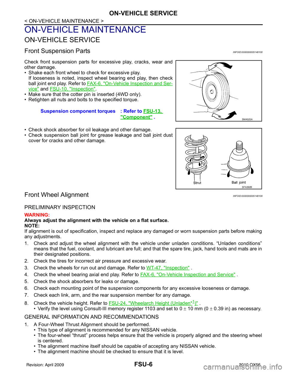
Front Suspension PartsINFOID:0000000005148108
Check front suspension parts for excessive play, cracks, wear and
other damage.
• Shake each front wheel to check for excessive play.If looseness is noted, inspect wheel bearing end play, then check
ball joint end play. Refer to FA X - 6 , "
On-Vehicle Inspection and Ser-
vice" and FSU-10, "Inspection".
• Make sure that the cotter pin is inserted (4WD only).
• Retighten all nuts and bolts to the specified torque.
• Check shock absorber for oil leakage and other damage.
• Check suspension ball joint for grease leakage and ball joint dust cover for cracks and other damage.
Front Wheel AlignmentINFOID:0000000005148109
PRELIMINARY INSPECTION
WARNING:
Always adjust the alignment with the vehicle on a flat surface.
NOTE:
If alignment is out of specificat ion, inspect and replace any damaged or worn suspension parts before making
any adjustments.
1. Check and adjust the wheel alignment with the vehicle under unladen conditions. “Unladen conditions”
means that the fuel, coolant, and lubricant are full; and that the spare tire, jack, hand tools and mats are in
their designated positions.
2. Check the tires for incorrect air pressure and excessive wear.
3. Check the wheels for run out and damage. Refer to WT-47, "
Inspection" .
4. Check the wheel bearing axial end play. Refer to FA X - 6 , "
On-Vehicle Inspection and Service" .
5. Check the shock absorbers for leaks or damage.
6. Check each mounting point of the suspension components for any excessive looseness or damage.
7. Check each link, arm, and the rear suspension member for any damage.
8. Check the vehicle height. Refer to FSU-24, "
Wheelarch Height (Unladen*1)" .
• Verify the level using Consult-III memory register 1103 and set to 0 ± 10 mm (0 ± 0.39 in) as necessary.
GENERAL INFORMATION AND RECOMMENDATIONS
1. A Four-Wheel Thrust Alignment should be performed.
• This type of alignment is recommended for any NISSAN vehicle.
• The four-wheel “thrust” process helps ensure that the vehicle is properly aligned and the steering wheel
is centered.
• The alignment machine itself should be ca pable of accepting any NISSAN vehicle.
• The alignment machine should be checked to ensure that it is level. Suspension component
torques : Refer to FSU-13,
"Component" . SMA525A
SFA392B
Revision: April 20092010 QX56