Page 329 of 360

________________________________________________ E_ m ___ e_r.::g ~e ___ n_c ~y:.- s;_ i_t _u :...:a:..:. t.:.: i...:o :...:n...:..:. s _ __,J_
& WARNING !continued)
• Before you check anything in the engine compartment, always
read and heed all WARNINGS~ page 263, "Engine compartment".
0 Note
• Applying a higher voltage booster battery will cause expensive
damage to sensitive electronic components, such as control units,
relays, radio, etc .
• There must be no electrical contact between the vehicles as
otherwise current could already start to flow as soon as the positive
(+) terminals are connected.
[ i) Tips
• The discharged battery must be properly connected to the
vehicle's electrical system. When jump starting or charging the
battery , never connect the negative ground cable to the battery
negative post because the battery manager system must be able to
detect the battery's state of charge. Always connect the negative
ground cable to the negative ground post of the battery manager
control unit .•
Use of jumper cables
Make sure to connect the jumper cable clamps in exactly
the order described below!
Fig. 251 Engine
compartment : Connec·
tors for jumper cables
and charger
Fig. 252 Jump starting
with the battery of
another vehicle: @
discharged vehicle
battery,
© booster
battery
The procedure described below for connecting jumper
cables is intended to provide a jump start for your vehicle.
Vehicle with discharged battery:
Turn off lights and accessories, move lever of automatic
transmission to
N (Neutral) or P (Park) and set parking
brake.
~
Vehicle care Do-it-yourself service irechnical data
Page 330 of 360

lllffl.___E_ m _ e _r-==g :...e_ n_ c...:y _ s_ i_t _u _a _t_ i_o _n_ s _______________________________________________ _
Conn ect POSITIVE
(+) to POSITIVE (+) (red )
- Remove the cover above the jump start connection.
- Open the red cover on the positive pole
~ page 327,
fig. 251.
1. Connect one end of the positive cable (red) on the
jump
start bolt~ page 327, fig. 252 G) (Bolts under red cover
= "positive") of the vehicle to be started @.
2. Connect the other end to the positive terminal @ of the
booster battery @.
Connect NEGATIVE (-) to NEGATIVE (-) (black)
3. Connect one end to the negat ive terminal 0 of the
booster battery ®·
4. Connect the other end of the negative cable (black) to the
jump start bolt@ (Bolts with hex head= "negative") of
the vehicle to be started @.
Starting the engine
- Start the engine of the vehicle with the booster battery.
Run the engine at a moderate speed.
- Start engine with discharged vehicle battery in the usual
manner.
- If the engine fails to start : do not keep the starter
cranking for longer than 10 seconds. Wait for about
30 seconds and then try again.
- With engine running, remove jumper cables from both
vehicles in the exact
reverse order .
- Close the red cover on the positive pole.
T he battery is vented to the outside to prevent gases from entering
th e vehicle interior. Make sure that the jumper clamps are well
connected with their
metal parts in full contact with the battery
terminals.
& WARNING
To avoid serious personal injury and damage to the vehicle , heed
all warnings and instructions of the jumper cable manufacturer.
If
in doubt, call for road service.
• Jumper cables must be long enough so that the vehicles do not
touch .
• When connecting jumper cables, make sure that they cannot
get caught in any moving parts in the engine compartment.
• Do not bend over the batteries -danger of chemical burns!
• The battery cell locking screws must be tightened securely.
• Before you check anything in the engine compartment , always
read and heed all WARNINGS ~ page 263, "Engine compartment".
0 Note
Improper hook-up of jumper cables can ruin the generator .
• Always connect POS ITIVE(+) to POS ITIVE(+), and NEGATIVE(-) to
NEGATIVE( -) ground post of the battery manager control unit .
• Check that all screw plugs on the battery cells are screwed in
firm ly. If not, tighten plugs prior to connecting clamp on negative
battery terminal.
• Please note that the procedure for connecting a jumper cable as
described above applies specifically to the case of your vehicle
being jump started . When you are giving a jump start to another
vehicle, do
not connect the negative(-) cable to the negative{-)
terminal on the discharged battery©~
page 327, fig. 252. Instead,
securely connect the negative(-) cable to either a solid metal
component that is firmly bolted to the engine block or to the engine ..
Page 331 of 360

________________________________________________ E_ m_ e_r ,,::g c..e_ n _ c..::y;._ s_ i_t _u _a_ t_ i_o _n_ s _ ___.ffllll
block itself. If the battery that is being charged does not vent to the
outside, escaping battery gas could ignite and explode! •
Emergency towing with commercial
tow truck
General hints
Your Audi requires special handling for towing.
The following information is to be used by commercial tow truck
operators who know how to operate their equipment safely.
• Never tow your Audi , towing will cause damage to the engine
and transmission.
• Never wrap the safety chains or winch cables around the brake
lines.
• To prevent unnecessary damage, your Audi must be transported
with a flat bed truck.
• To load the vehicle on to the flat bed, use the towing loop found
in the vehicle tools and attach to the front or rear anchorage
~ page 329 and ~ page 330.
& WARNING
A vehicle being towed is not safe for passengers. Never allow
anyone to ride in a vehicle being towed, for any reason. •
Front towing loop
Do not install the front towing loop until it is needed.
Fig. 253 Front
bumper: removing the
cover cap
Fig . 254 Front
bumper: screwing in
the towing loop
The towing loop fi ts into the thread ed hole located on the
r ight side of the front bumper and covered by a small cover
when not in use.
- Remove the towing loop from the vehicle toolkit
~ page 310.
- Press the cover in by applying short strong pressure to
the bottom part to release it from the bumper~ fig. 253.
- Screw t he towing loop tightly into the threaded hole as
far as it will go
~ fig. 254. ~
Vehicle care Do-it-yourself service irechnical data
Page 332 of 360

IIIII...__E_ m _ e _r.;:g '-e_ n_ c-=y _ s_ i_t _u _a _t_ i_o _n_ s _______________________________________________ _
When it is no longer needed, unscrew the towing loop and put it
back into the vehicle toolkit. Be sure to have the towing loop stored
in the vehicle at all times.
& WARNING
If the towing loop is not screwed in as far as it will go, the thread
can pull out when the vehicle is towed -potential risk of an
accident. •
Rear towing loop
Do not install the rear towing loop until it is needed.
Fig. 255 Rear bumper :
Screwing in towing
loop
On the right side of the rear bumper there is a threaded hole
for the towing loop. The threaded hole is protected by a
cover.
- Remove the towing loop from the vehicle toolkit
=>
page 310.
- Press the cover in by applying short strong pressure to
the bottom part to release it from the bumper=> fig. 255.
Screw the towing loop tightly into the threaded hole as
far as it will go.
Unscrew the towing loop again after use and install the cover in the
bumper . Install the cover in the bumper. Return the towing loop to
the toolkit. Be sure to have the towing loop stored in the vehicle at
all times.
& WARNING
If the towing loop is not screwed in as far as it will go, the thread
can pull out when the vehicle is towed -potential risk of an
accident. •
Loading the vehicle onto a flat bed truck
Front hook up
Fig. 256 Vehicle on flat
bed truck
-Align the vehicle with the centerline of the car carrier
ramp.
- Attach the winch hook to the front towline eye previously
installed.
Rear hook up
- Align the vehicle with the centerline of the car carrier
ramp.
Page 333 of 360
![AUDI A5 COUPE 2010 Owners Manual Emergency situations -
----------------=-~----
- Attach the winch hook to the rear towline eye previously
installed.
[ i ] Tips
Check carefully to make sure the hook -up is secure bef AUDI A5 COUPE 2010 Owners Manual Emergency situations -
----------------=-~----
- Attach the winch hook to the rear towline eye previously
installed.
[ i ] Tips
Check carefully to make sure the hook -up is secure bef](/manual-img/6/57582/w960_57582-332.png)
Emergency situations -
----------------=-~----
- Attach the winch hook to the rear towline eye previously
installed.
[ i ] Tips
Check carefully to make sure the hook -up is secure before moving
the car up the flatbed truck ramp. •
Lifting vehicle
Lifting with workshop hoist and with floor
jack
The vehicle may only be lifted at the lifting points illus
trated.
Fig . 257 Front lifting
point
- Read and heed WARNING~&.
Fig. 258 Rear lifting
point
- Locate li fting points ~ fig. 257 and ~ fig. 258.
- Adjust lifting arms of workshop hoist or floor jack to
match vehicle lifting points.
- Insert a rubber pad between the floor jack/workshop
hoist and the lifting points.
If you must lift your vehicle with a floor jack to work underneath , be
sure the vehicle is safely supported on stands intended for this
purpose .
Front lifting point
The lifting point is located on the floor pan reinforcement about at
the same level as the jack mounting point=> fig. 257.
Do not lift the
vehicle at the vertical sill reinforcement .
Rear lifting point
The lifting point is located on the vertical reinforcement of the lower
s ill for the onboard jack=> fig. 258.
Lifting vvith vehicle jack
Refer to => page 315 .
Vehicle care Do-it-yourself service irechnical data
Page 334 of 360

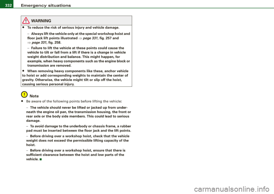
-Emergency situations PW:f..._--=---=----------------
& WARNING
• To reduce the risk of serious injury and vehicle damage .
- Always lift the vehicle only at the special workshop hoist and
floor jack lift points illustrated~ page
331, fig. 257 and
~ page 331, fig. 258.
- Failure to lift the vehicle at these points could cause the
vehicle to tilt or fall from a lift if there is a change in vehicle
weight distribution and balance. This might happen, for
example, when heavy components such as the engine block or
transmission are removed.
• When removing heavy components like these, anchor vehicle
to hoist or add corresponding weights to maintain the center of
gravity. Otherwise, the vehicle might tilt or slip off the hoist,
causing serious personal injury.
0 Note
• Be aware of the following points before lifting the vehicle:
- The vehicle should never be lifted or jacked up from under
neath the engine oil pan, the transmission housing, the front or
rear axle or the body side members . This could lead to serious
damage.
- To avoid damage to the underbody or chassis frame, a rubber
pad must be inserted between the floor jack and the lift points.
- Before driving over a workshop hoist, check that the vehicle
weight does not exceed the permissible lifting capacity of the hoist .
- Before driving over a workshop hoist, ensure that there is sufficient clearance between the hoist and low parts of the
vehicle. •
Page 335 of 360
Emergency situations Ill
-------------=--=----
• Do-it-yourself service
Page 336 of 360

ffl,__ __ G_e_ n_e_ ra_ l_i_n _f _o _ r_ m_ a_ t_io _ n __________________________________________________ _
General information
Explanation of technical data
Some of the technical data listed in this manual requires
further explanation.
The technical data for your vehicle is listed in the charts starting on
~ page 337. This section provides general information, notes and
restrictions which apply to this data. •
Vehicle identification
The key data is given on the vehicle identification number
(VIN) plate and the vehicle data sticker.
Fig. 259 Vehicle Identi
fication Number (VIN)
plate: location on
driver's side dash
panel Fig
. 260 The vehicle
identification label -
inside the luggage
compartment
The Vehicle Identification Number (VIN)
is located on the driver's side so that it is visible from the outside
through the windshield~ fig. 259.
The vehicle identification label
is located in the luggage compartment near the battery .
The label ~ fig. 260 shows the following vehicle data:
© Production control No.
0 Vehicle identification No.
© Type code number
© Type designation/engine output in Kilowatts
© Engine and transmission code letter
© Paint No./lnterior
0 Optional equipment No.'s
Vehicle data 2 to 7 are also found in your Warranty
& Maintenance
booklet .
The safety compliance sticker
is your assurance that your new vehicle complies with all applicable
Federal Motor Vehicle Safety Standards which were in effect at the
time the vehicle was manufactured. You can find this sticker on the ._