2009 SUBARU TRIBECA tire pressure
[x] Cancel search: tire pressurePage 1117 of 2453
WT-11
Tire Pressure Monitoring System
WHEEL AND TIRE SYSTEM
6. Tire Pressure Monitoring
System
A: REMOVAL
1. TRANSMITTER (TIRE PRESSURE SEN-
SOR)
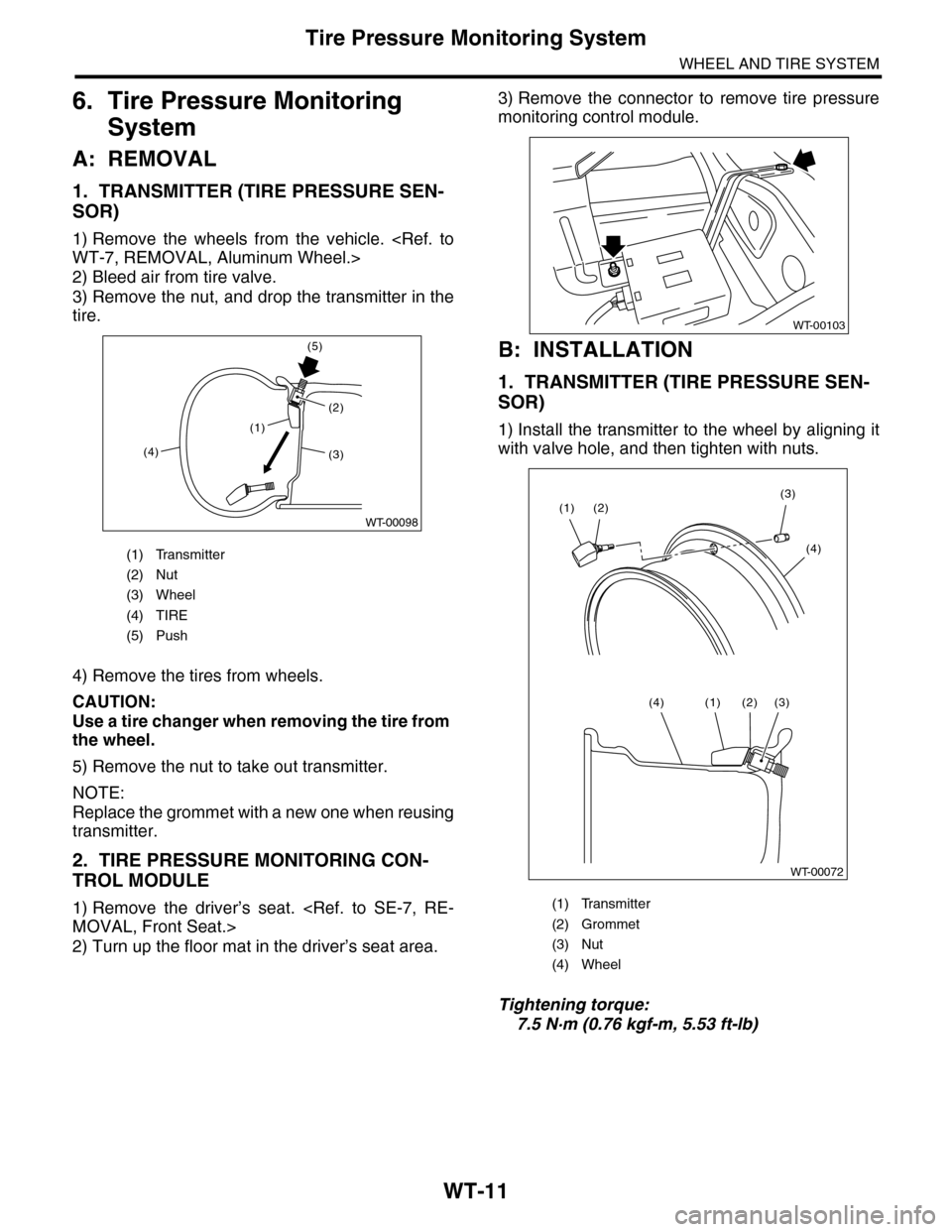
1) Remove the wheels from the vehicle.
2) Bleed air from tire valve.
3) Remove the nut, and drop the transmitter in the
tire.
4) Remove the tires from wheels.
CAUTION:
Use a tire changer when removing the tire from
the wheel.
5) Remove the nut to take out transmitter.
NOTE:
Replace the grommet with a new one when reusing
transmitter.
2. TIRE PRESSURE MONITORING CON-
TROL MODULE
1) Remove the driver’s seat.
2) Turn up the floor mat in the driver’s seat area.
3) Remove the connector to remove tire pressure
monitoring control module.
B: INSTALLATION
1. TRANSMITTER (TIRE PRESSURE SEN-
SOR)
1) Install the transmitter to the wheel by aligning it
with valve hole, and then tighten with nuts.
Tightening torque:
7.5 N·m (0.76 kgf-m, 5.53 ft-lb)
(1) Transmitter
(2) Nut
(3) Wheel
(4) TIRE
(5) Push
(1)
(4)
(5)
(2)
WT-00098
(3)
(1) Transmitter
(2) Grommet
(3) Nut
(4) Wheel
WT-00103
WT-00072
(2)(3)
(4)
(1)
(3)(2)(1)(4)
Page 1118 of 2453
WT-12
Tire Pressure Monitoring System
WHEEL AND TIRE SYSTEM
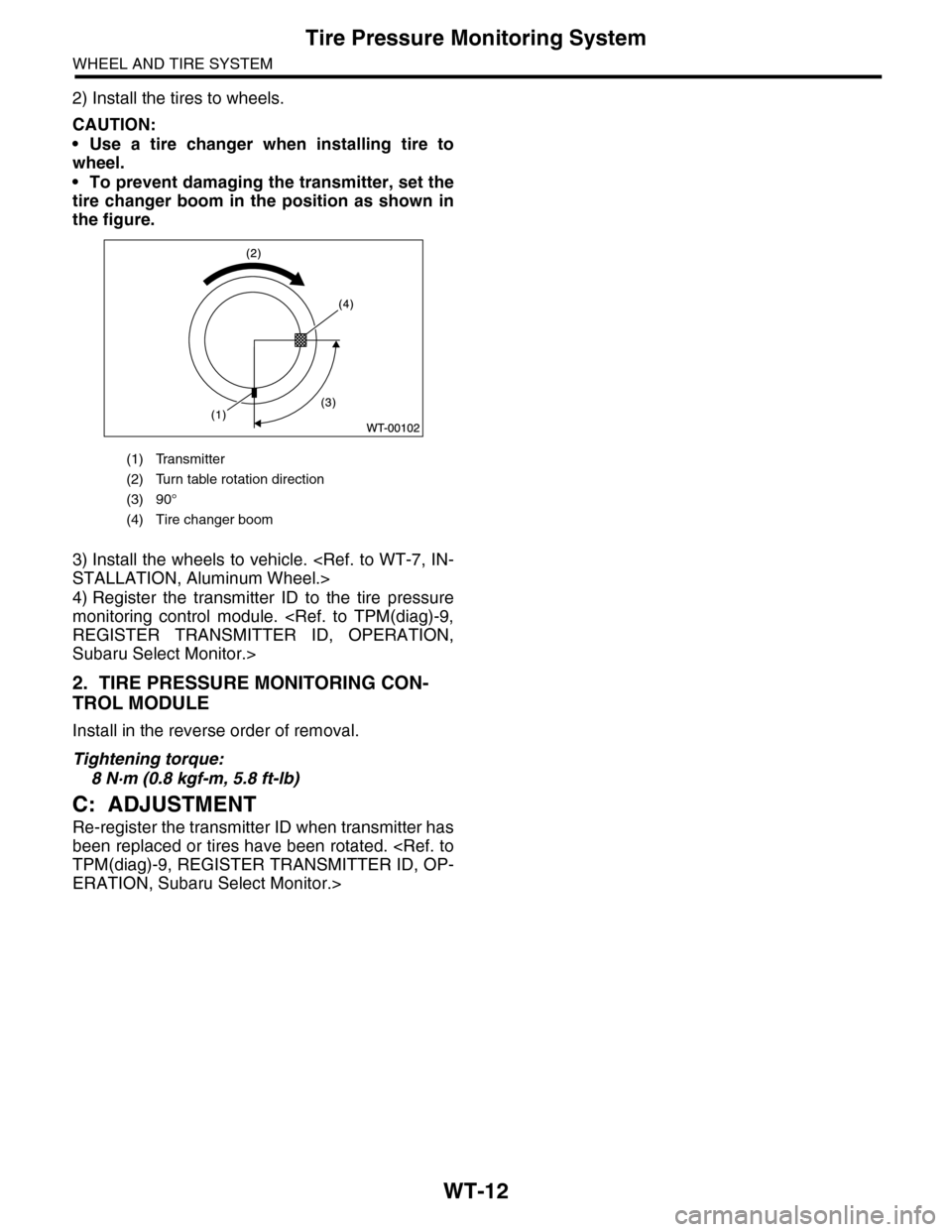
2) Install the tires to wheels.
CAUTION:
•Use a tire changer when installing tire to
wheel.
•To prevent damaging the transmitter, set the
tire changer boom in the position as shown in
the figure.
3) Install the wheels to vehicle.
4) Register the transmitter ID to the tire pressure
monitoring control module.
Subaru Select Monitor.>
2. TIRE PRESSURE MONITORING CON-
TROL MODULE
Install in the reverse order of removal.
Tightening torque:
8 N·m (0.8 kgf-m, 5.8 ft-lb)
C: ADJUSTMENT
Re-register the transmitter ID when transmitter has
been replaced or tires have been rotated.
ERATION, Subaru Select Monitor.>
(1) Transmitter
(2) Turn table rotation direction
(3) 90°
(4) Tire changer boom
Page 1120 of 2453
WT-14
General Diagnostic Table
WHEEL AND TIRE SYSTEM
8. General Diagnostic Table
A: INSPECTION
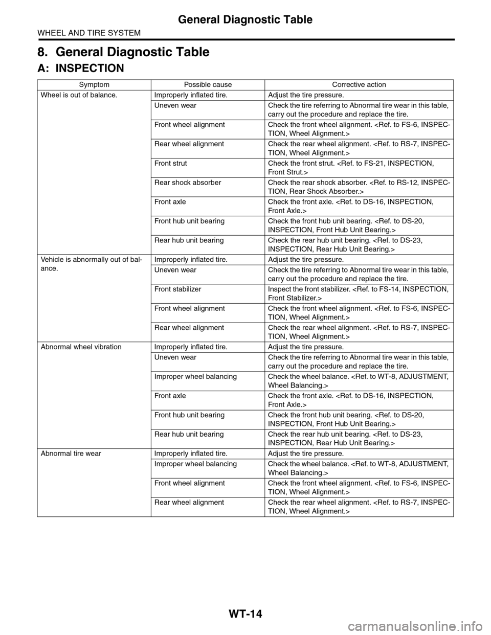
Symptom Possible cause Corrective action
Wheel is out of balance. Improperly inflated tire. Adjust the tire pressure.
Uneven wear Check the tire referring to Abnormal tire wear in this table,
carry out the procedure and replace the tire.
Fr o nt w h ee l al ig n me nt Ch eck t he f r on t w he e l a l ig n me nt . < R ef. to F S - 6, I N S P E C -
TION, Wheel Alignment.>
Rear wheel alignment Check the rear wheel alignment.
Fr o nt s tr u t Ch eck th e f r o n t s tr ut .
Rear shock absorber Check the rear shock absorber.
Fr o nt a xl e C h eck th e f r o n t a xl e. < R e f. t o D S - 1 6, I N S P E C T IO N,
Fr o n t A x le. >
Fr o nt h ub un i t b e ar i n g Ch eck th e f r o n t h ub u ni t b e ar i n g. < Re f. t o DS - 2 0,
INSPECTION, Front Hub Unit Bearing.>
Rear hub unit bearing Check the rear hub unit bearing.
Ve h i c l e i s a b n o r m a l l y o u t o f b a l -
ance.
Improperly inflated tire. Adjust the tire pressure.
Uneven wear Check the tire referring to Abnormal tire wear in this table,
carry out the procedure and replace the tire.
Fr o nt s ta b il i ze r I ns p ec t t h e f r o nt st a bi l izer. < R e f. t o F S - 14 , IN SP E C T I ON,
Fr o n t S t a bi l izer. >
Fr o nt w h ee l al ig n me nt Ch eck t he f r on t w he e l a l ig n me nt . < R ef. to F S - 6, I N S P E C -
TION, Wheel Alignment.>
Rear wheel alignment Check the rear wheel alignment.
Abnormal wheel vibration Improperly inflated tire. Adjust the tire pressure.
Uneven wear Check the tire referring to Abnormal tire wear in this table,
carry out the procedure and replace the tire.
Improper wheel balancing Check the wheel balance.
Fr o nt a xl e C h eck th e f r o n t a xl e. < R e f. t o D S - 1 6, I N S P E C T IO N,
Fr o n t A x le. >
Fr o nt h ub un i t b e ar i n g Ch eck th e f r o n t h ub u ni t b e ar i n g. < Re f. t o DS - 2 0,
INSPECTION, Front Hub Unit Bearing.>
Rear hub unit bearing Check the rear hub unit bearing.
Abnormal tire wear Improperly inflated tire. Adjust the tire pressure.
Improper wheel balancing Check the wheel balance.
Fr o nt w h ee l al ig n me nt Ch eck t he f r on t w he e l a l ig n me nt . < R ef. to F S - 6, I N S P E C -
TION, Wheel Alignment.>
Rear wheel alignment Check the rear wheel alignment.
Page 2007 of 2453
PM-24
Suspension
PERIODIC MAINTENANCE SERVICES
17.Suspension
A: INSPECTION
1. SUSPENSION BALL JOINT
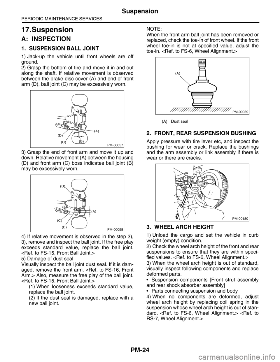
1) Jack-up the vehicle until front wheels are off
ground.
2) Grasp the bottom of tire and move it in and out
along the shaft. If relative movement is observed
between the brake disc cover (A) and end of front
arm (D), ball joint (C) may be excessively worn.
3) Grasp the end of front arm and move it up and
down. Relative movement (A) between the housing
(D) and front arm (C) boss indicates ball joint (B)
may be excessively worn.
4) If relative movement is observed in the step 2),
3), remove and inspect the ball joint. If the free play
exceeds standard value, replace the ball joint.
5) Damage of dust seal
Visually inspect the ball joint dust seal. If it is dam-
aged, remove the front arm.
(1) When looseness exceeds standard value,
replace the ball joint.
(2) If the dust seal is damaged, replace with a
new ball joint.
NOTE:
When the front arm ball joint has been removed or
replaced, check the toe-in of front wheel. If the front
wheel toe-in is not at specified value, adjust the
toe-in.
2. FRONT, REAR SUSPENSION BUSHING
Apply pressure with tire lever etc, and inspect the
bushing for wear or crack. Replace the bushings
and the arm assembly or link assembly if there is
wear or there are cracks.
3. WHEEL ARCH HEIGHT
1) Unload the cargo and set the vehicle in curb
weight (empty) condition.
2) Check the wheel arch height of the front and rear
suspensions to ensure that they are within speci-
fied values.
3) When the wheel arch height is out of standard,
visually inspect following components and replace
deformed parts.
•Suspension components [Front strut assembly
and rear shock absorber assembly]
•Parts connecting suspension and body
4) When no components are deformed, adjust
wheel arch height by replacing coil spring in the
suspension whose wheel arch height is out of stan-
dard.
PM-00057
(A)
(B)(C)
(D)
PM-00058
(A)
(B)
(C)
(D)
(A) Dust seal
PM-00059
(A)
PM-00180
Page 2297 of 2453
WI-13
Basic Diagnostic Procedure
WIRING SYSTEM
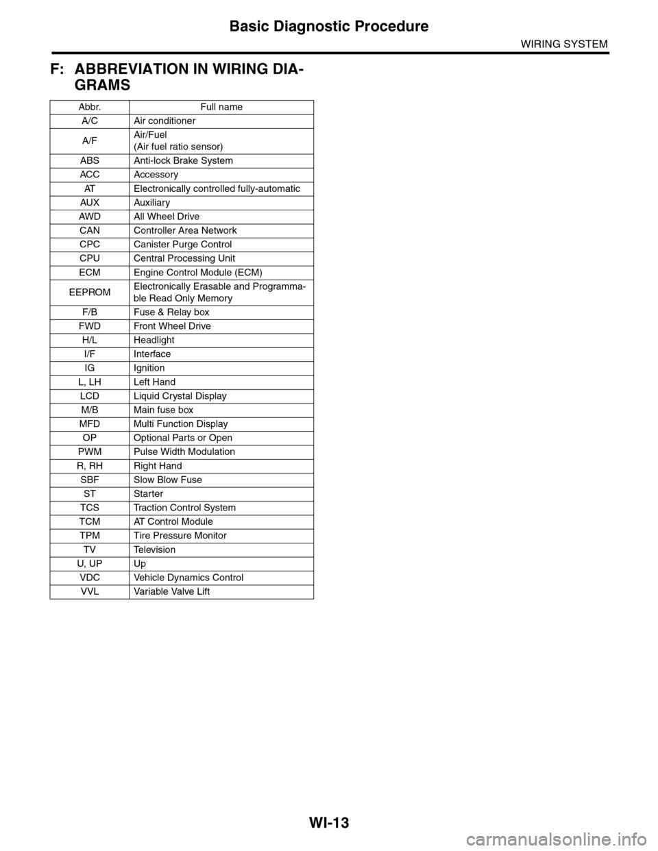
F: ABBREVIATION IN WIRING DIA-
GRAMS
Abbr. Full name
A/C Air conditioner
A/FAir/Fuel
(Air fuel ratio sensor)
ABS Anti-lock Brake System
ACC Accessor y
AT E l e c t r o n i c a l l y c o n t r o l l e d f u l l y - a u t o m a t i c
AUX Auxiliar y
AW D A ll W he e l D r i ve
CAN Controller Area Network
CPC Canister Purge Control
CPU Central Processing Unit
ECM Engine Control Module (ECM)
EEPROMElectronically Erasable and Programma-
ble Read Only Memory
F/B Fuse & Relay box
FWD Front Wheel Drive
H/L Headlight
I/F Interface
IG Ignition
L, LH Left Hand
LCD Liquid Crystal Display
M/B Main fuse box
MFD Multi Function Display
OP Optional Parts or Open
PWM Pulse Width Modulation
R, RH Right Hand
SBF Slow Blow Fuse
ST Starter
TCS Traction Control System
TCM AT Control Module
TPM Tire Pressure Monitor
TV Television
U, UP Up
VDC Vehicle Dynamics Control
VVL Variable Valve Lift
Page 2343 of 2453
WI-59
TPM Control System
WIRING SYSTEM
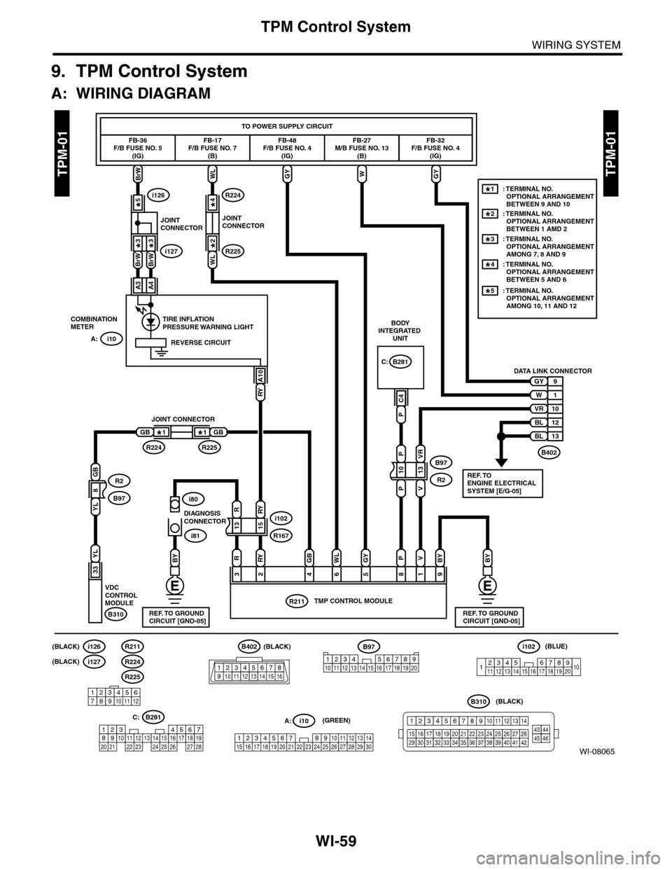
9. TPM Control System
A: WIRING DIAGRAM
WI-08065
TPM-01TPM-01
DIAGNOSISCONNECTOR
TMP CONTROL MODULE
COMBINATIONMETER
REVERSE CIRCUIT
TIRE INFLATIONPRESSURE WARNING LIGHT
3
1315
A10
642
1310
18
C4
RRYGBWL
5
GY
GY
RRY
RY
P
P
V
PV
i102
R167
i10A:
R2
B97
B97
R2
i80
i81
DATA LINK CONNECTOR
B402
R211
BY
9
BY33
YL
8
YL
GB
VDCCONTROLMODULE
B310
GYW
FB-32F/B FUSE NO. 4(IG)
TO POWER SUPPLY CIRCUIT
B281C:
BODYINTEGRATED UNIT
PVR
REF. TO GROUNDCIRCUIT [GND-05]
REF. TO ENGINE ELECTRICALSYSTEM [E/G-05]
BY
REF. TO GROUNDCIRCUIT [GND-05]
B97
234 567891112 13 14 17 18 19 201101516
B281C:
56782194310242223 25111213141526 27 281617181920 21
FB-36F/B FUSE NO. 5(IG)
FB-17F/B FUSE NO. 7(B)
FB-48F/B FUSE NO. 4(IG)
FB-27M/B FUSE NO. 13(B)
GY
W
VR
BL
BL
B402
123 8910413 14 15 165671112
WL
JOINTCONNECTOR
R224
R225
4*
2*
GBGB
JOINT CONNECTOR
R224R225
1*1*
BrWWL
A3A4
BrWBrW
JOINTCONNECTOR
i126
i127
5*
3*3*
: TERMINAL NO. OPTIONAL ARRANGEMENT BETWEEN 1 AMD 2
2*
: TERMINAL NO. OPTIONAL ARRANGEMENT AMONG 7, 8 AND 9
3*
: TERMINAL NO. OPTIONAL ARRANGEMENT BETWEEN 5 AND 6
4*
: TERMINAL NO. OPTIONAL ARRANGEMENT AMONG 10, 11 AND 12
5*
: TERMINAL NO. OPTIONAL ARRANGEMENT BETWEEN 9 AND 10
1*
123456789101112
i126(BLACK)
i127(BLACK)
R211
R224
R225
B310
i10
19 20 2115 16 17 182223242526272829301234568910 11 12 13 147
A:1234
1516171819202122232425262728293031323334353637383940414245464344568910 11 12 13 147
1234567891413121110151617181920
i102(BLUE)
9
1
10
12
13
(BLACK)
(GREEN)
(BLACK)
Page 2416 of 2453
WI-132
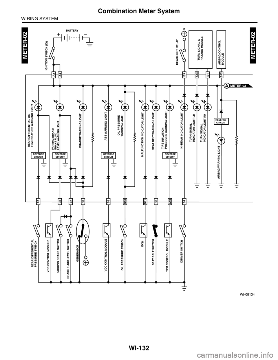
Combination Meter System
WIRING SYSTEM
WI-08134
METER-02METER-02
ECM
TPM
CONTROL M
ODULE
VDC CONTROL M
ODULE
OIL P
RESSURE SW
ITCH
GENERATOR
BRAKE FLU
ID LEV
EL SWITCH
AIRBAG WARNING LIGHT
HEADLIGHT RELAYAIRBAG CONTROLMODULE
ABS WARNING LIGHT
CHARGE WARNING LIGHTPARKING BRAKE/BRAKE FLUIDLEVEL WARNING LIGHT
VDC CONTROL M
ODULE
PARKING BRAKE SWITCH
REAR DIFFE
RENTIAL
PRESSURE SWITCH
SEA
T BELT W
ARNING LIG
HT
SEAT BELT S
WITCH
A3
IGNITION SWITCH (IG)
A4
REVERSECIRCUIT
OIL PRESSUREWARNING LIGHT
MALFUNCTION INDICATOR LIGHT
HI-BEAM INDICATOR LIGHT
TURN SIGNAL &HAZARD MODULE
TURN SIGNALINDICATOR LIGHT LHTURN SIGNALINDICATOR LIGHT RH
REVERSECIRCUIT
REVERSECIRCUIT
B
B3A14B1B12
METER-03A
BATTERY
B8B7B9B6B10B5B4B11
REAR DIFFERENTIAL OIL TEMPERATURE WARNING LIGHT
REVERSECIRCUIT
DIMMER SWITCH
TIRE INFLATION PRESSURE WARNING LIGHT
REVERSECIRCUIT
A10A7