Page 1080 of 2453
VDC(diag)-88
General Diagnostic Table
VEHICLE DYNAMICS CONTROL (VDC) (DIAGNOSTICS)
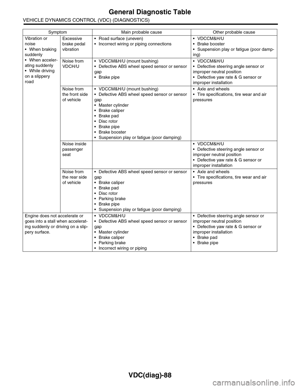
Vibration or
noise
•When braking
suddenly
•When acceler-
ating suddenly
•While driving
on a slippery
road
Excessive
brake pedal
vibration
•Road surface (uneven)
•Incorrect wiring or piping connections
•VDCCM&H/U
•Brake booster
•Suspension play or fatigue (poor damp-
ing)
Noise from
VDCH/U
•VDCCM&H/U (mount bushing)
•Defective ABS wheel speed sensor or sensor
gap
•Brake pipe
•VDCCM&H/U
•Defective steering angle sensor or
improper neutral position
•Defective yaw rate & G sensor or
improper installation
Noise from
the front side
of vehicle
•VDCCM&H/U (mount bushing)
•Defective ABS wheel speed sensor or sensor
gap
•Master cylinder
•Brake caliper
•Brake pad
•Disc rotor
•Brake pipe
•Brake booster
•Suspension play or fatigue (poor damping)
•Axle and wheels
•Tire specifications, tire wear and air
pressures
Noise inside
passenger
seat
•VDCCM&H/U
•Defective steering angle sensor or
improper neutral position
•Defective yaw rate & G sensor or
improper installation
Noise from
the rear side
of vehicle
•Defective ABS wheel speed sensor or sensor
gap
•Brake caliper
•Brake pad
•Disc rotor
•Parking brake
•Brake pipe
•Suspension play or fatigue (poor damping)
•Axle and wheels
•Tire specifications, tire wear and air
pressures
Engine does not accelerate or
goes into a stall when accelerat-
ing suddenly or driving on a slip-
pery surface.
•VDCCM&H/U
•Defective ABS wheel speed sensor or sensor
gap
•Master cylinder
•Brake caliper
•Parking brake
•Incorrect wiring or piping
•Defective steering angle sensor or
improper neutral position
•Defective yaw rate & G sensor or
improper installation
•Brake pad
•Brake pipe
Symptom Main probable cause Other probable cause
Page 1081 of 2453
VDC(diag)-89
General Diagnostic Table
VEHICLE DYNAMICS CONTROL (VDC) (DIAGNOSTICS)
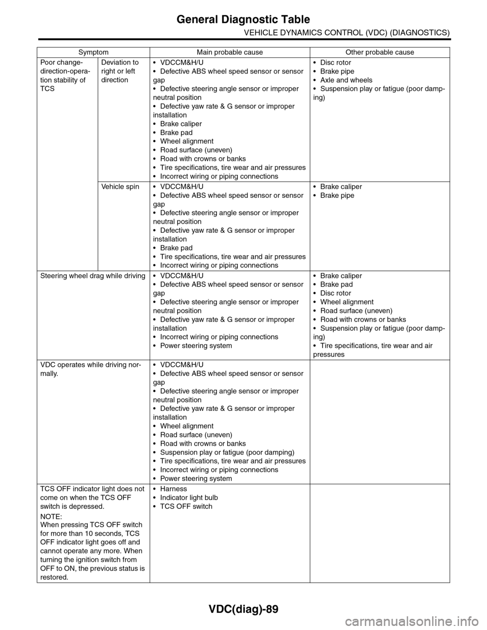
Po or ch a ng e -
direction-opera-
tion stability of
TCS
Deviation to
right or left
direction
•VDCCM&H/U
•Defective ABS wheel speed sensor or sensor
gap
•Defective steering angle sensor or improper
neutral position
•Defective yaw rate & G sensor or improper
installation
•Brake caliper
•Brake pad
•Wheel alignment
•Road surface (uneven)
•Road with crowns or banks
•Tire specifications, tire wear and air pressures
•Incorrect wiring or piping connections
•Disc rotor
•Brake pipe
•Axle and wheels
•Suspension play or fatigue (poor damp-
ing)
Ve h i c l e s p i n • V D C C M & H / U
•Defective ABS wheel speed sensor or sensor
gap
•Defective steering angle sensor or improper
neutral position
•Defective yaw rate & G sensor or improper
installation
•Brake pad
•Tire specifications, tire wear and air pressures
•Incorrect wiring or piping connections
•Brake caliper
•Brake pipe
Steering wheel drag while driving • VDCCM&H/U
•Defective ABS wheel speed sensor or sensor
gap
•Defective steering angle sensor or improper
neutral position
•Defective yaw rate & G sensor or improper
installation
•Incorrect wiring or piping connections
•Power steering system
•Brake caliper
•Brake pad
•Disc rotor
•Wheel alignment
•Road surface (uneven)
•Road with crowns or banks
•Suspension play or fatigue (poor damp-
ing)
•Tire specifications, tire wear and air
pressures
VDC operates while driving nor-
mally.
•VDCCM&H/U
•Defective ABS wheel speed sensor or sensor
gap
•Defective steering angle sensor or improper
neutral position
•Defective yaw rate & G sensor or improper
installation
•Wheel alignment
•Road surface (uneven)
•Road with crowns or banks
•Suspension play or fatigue (poor damping)
•Tire specifications, tire wear and air pressures
•Incorrect wiring or piping connections
•Power steering system
TCS OFF indicator light does not
come on when the TCS OFF
switch is depressed.
NOTE:When pressing TCS OFF switch
for more than 10 seconds, TCS
OFF indicator light goes off and
cannot operate any more. When
turning the ignition switch from
OFF to ON, the previous status is
restored.
•Harness
•Indicator light bulb
•TCS OFF switch
Symptom Main probable cause Other probable cause
Page 1108 of 2453
WT-2
General Description
WHEEL AND TIRE SYSTEM
1. General Description
A: SPECIFICATION
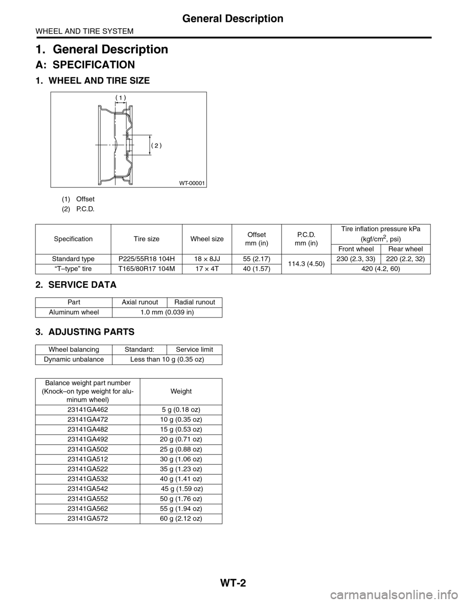
1. WHEEL AND TIRE SIZE
2. SERVICE DATA
3. ADJUSTING PARTS
(1) Offset
(2) P.C.D.
WT-00001
Specification Tire size Wheel sizeOffset
mm (in)
P. C . D .
mm (in)
Tire inflation pressure kPa
(kgf/cm2, psi)
Front wheel Rear wheel
Standard type P225/55R18 104H 18 × 8JJ 55 (2.17)114.3 (4.50)230 (2.3, 33) 220 (2.2, 32)
“T–type” tire T165/80R17 104M 17 × 4T 40 (1.57) 420 (4.2, 60)
Par t Axial r unout Radial r unout
Aluminum wheel 1.0 mm (0.039 in)
Wheel balancing Standard: Service limit
Dynamic unbalance Less than 10 g (0.35 oz)
Balance weight par t number
(Knock–on type weight for alu-
minum wheel)
Weight
23141GA462 5 g (0.18 oz)
23141GA472 10 g (0.35 oz)
23141GA482 15 g (0.53 oz)
23141GA492 20 g (0.71 oz)
23141GA502 25 g (0.88 oz)
23141GA512 30 g (1.06 oz)
23141GA522 35 g (1.23 oz)
23141GA532 40 g (1.41 oz)
23141GA542 45 g (1.59 oz)
23141GA552 50 g (1.76 oz)
23141GA562 55 g (1.94 oz)
23141GA572 60 g (2.12 oz)
Page 1110 of 2453
WT-4
General Description
WHEEL AND TIRE SYSTEM
B: COMPONENT
1. TIRE PRESSURE MONITORING SYSTEM
(1) Transmitter (4) CapTightening torque: N·m (kgf-m, ft-lb)
(2) Grommet (5) Tire pressure monitoring control
module
T1: 7.5 (0.76, 5.53)
(3) NutT2: 8 (0.8, 5.8)
WT-00069
(4)
(3)
(2)
(1)
T1
T2
T2
(5)
Page 1111 of 2453
WT-5
General Description
WHEEL AND TIRE SYSTEM
2. SPARE TIRE HOIST
C: PREPARATION TOOL
1. GENERAL TOOL
(1) Spare tire guide Tightening torque: N·m (kgf-m, ft-lb)
(2) Spare tire hoist T1: 33 (3.7, 24.3)
TOOL NAME REMARKS
Air pressure gauge Used for measuring tire air pressure.
Dial gauge with
magnet standUsed for measuring wheel runout.
Wheel balancer Used for adjusting wheel balance.
Page 1112 of 2453
WT-6
Tire
WHEEL AND TIRE SYSTEM
2. Tire
A: INSPECTION
1) Take stones, glass, nails etc. out of the tread
groove.
2) Replace tires in the following cases.
CAUTION:
•When replacing a tire, make sure to use only
tires of the same size, construction and load
range as originally installed.
•Use a tire changer when removing the tire
from the wheel.
•On models equipped with tire pressure mon-
itoring systems, do not use the bead breaker in
a 90° area centered on the transmitter to pre-
vent damaging the transmitter.
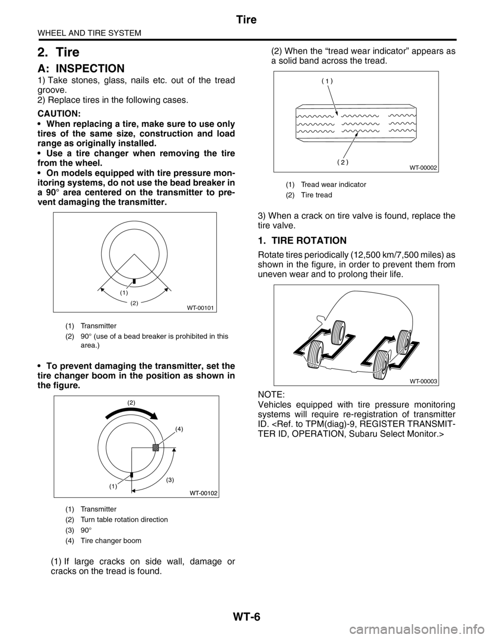
•To prevent damaging the transmitter, set the
tire changer boom in the position as shown in
the figure.
(1) If large cracks on side wall, damage or
cracks on the tread is found.
(2) When the “tread wear indicator” appears as
a solid band across the tread.
3) When a crack on tire valve is found, replace the
tire valve.
1. TIRE ROTATION
Rotate tires periodically (12,500 km/7,500 miles) as
shown in the figure, in order to prevent them from
uneven wear and to prolong their life.
NOTE:
Vehicles equipped with tire pressure monitoring
systems will require re-registration of transmitter
ID.
TER ID, OPERATION, Subaru Select Monitor.>
(1) Transmitter
(2) 90° (use of a bead breaker is prohibited in this
area.)
(1) Transmitter
(2) Turn table rotation direction
(3) 90°
(4) Tire changer boom
(1)
WT-00101(2)
(1) Tread wear indicator
(2) Tire tread
WT-00002
WT-00003
Page 1114 of 2453
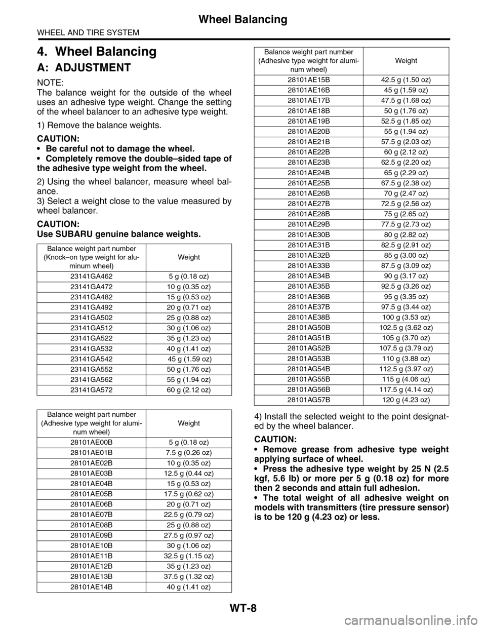
WT-8
Wheel Balancing
WHEEL AND TIRE SYSTEM
4. Wheel Balancing
A: ADJUSTMENT
NOTE:
The balance weight for the outside of the wheel
uses an adhesive type weight. Change the setting
of the wheel balancer to an adhesive type weight.
1) Remove the balance weights.
CAUTION:
•Be careful not to damage the wheel.
•Completely remove the double–sided tape of
the adhesive type weight from the wheel.
2) Using the wheel balancer, measure wheel bal-
ance.
3) Select a weight close to the value measured by
wheel balancer.
CAUTION:
Use SUBARU genuine balance weights.
4) Install the selected weight to the point designat-
ed by the wheel balancer.
CAUTION:
•Remove grease from adhesive type weight
applying surface of wheel.
•Press the adhesive type weight by 25 N (2.5
kgf, 5.6 lb) or more per 5 g (0.18 oz) for more
then 2 seconds and attain full adhesion.
•The total weight of all adhesive weight on
models with transmitters (tire pressure sensor)
is to be 120 g (4.23 oz) or less.
Balance weight par t number
(Knock–on type weight for alu-
minum wheel)
Weight
23141GA462 5 g (0.18 oz)
23141GA472 10 g (0.35 oz)
23141GA482 15 g (0.53 oz)
23141GA492 20 g (0.71 oz)
23141GA502 25 g (0.88 oz)
23141GA512 30 g (1.06 oz)
23141GA522 35 g (1.23 oz)
23141GA532 40 g (1.41 oz)
23141GA542 45 g (1.59 oz)
23141GA552 50 g (1.76 oz)
23141GA562 55 g (1.94 oz)
23141GA572 60 g (2.12 oz)
Balance weight par t number
(Adhesive type weight for alumi-
num wheel)
Weight
28101AE00B 5 g (0.18 oz)
28101AE01B 7.5 g (0.26 oz)
28101AE02B 10 g (0.35 oz)
28101AE03B 12.5 g (0.44 oz)
28101AE04B 15 g (0.53 oz)
28101AE05B 17.5 g (0.62 oz)
28101AE06B 20 g (0.71 oz)
28101AE07B 22.5 g (0.79 oz)
28101AE08B 25 g (0.88 oz)
28101AE09B 27.5 g (0.97 oz)
28101AE10B 30 g (1.06 oz)
28101AE11B 32.5 g (1.15 oz)
28101AE12B 35 g (1.23 oz)
28101AE13B 37.5 g (1.32 oz)
28101AE14B 40 g (1.41 oz)
28101AE15B 42.5 g (1.50 oz)
28101AE16B 45 g (1.59 oz)
28101AE17B 47.5 g (1.68 oz)
28101AE18B 50 g (1.76 oz)
28101AE19B 52.5 g (1.85 oz)
28101AE20B 55 g (1.94 oz)
28101AE21B 57.5 g (2.03 oz)
28101AE22B 60 g (2.12 oz)
28101AE23B 62.5 g (2.20 oz)
28101AE24B 65 g (2.29 oz)
28101AE25B 67.5 g (2.38 oz)
28101AE26B 70 g (2.47 oz)
28101AE27B 72.5 g (2.56 oz)
28101AE28B 75 g (2.65 oz)
28101AE29B 77.5 g (2.73 oz)
28101AE30B 80 g (2.82 oz)
28101AE31B 82.5 g (2.91 oz)
28101AE32B 85 g (3.00 oz)
28101AE33B 87.5 g (3.09 oz)
28101AE34B 90 g (3.17 oz)
28101AE35B 92.5 g (3.26 oz)
28101AE36B 95 g (3.35 oz)
28101AE37B 97.5 g (3.44 oz)
28101AE38B 100 g (3.53 oz)
28101AG50B 102.5 g (3.62 oz)
28101AG51B 105 g (3.70 oz)
28101AG52B 107.5 g (3.79 oz)
28101AG53B 110 g (3.88 oz)
28101AG54B 112.5 g (3.97 oz)
28101AG55B 115 g (4.06 oz)
28101AG56B 117.5 g (4.14 oz)
28101AG57B 120 g (4.23 oz)
Balance weight part number
(Adhesive type weight for alumi-
num wheel)
Weight
Page 1116 of 2453
WT-10
“T–type” Tire
WHEEL AND TIRE SYSTEM
5. “T–type” Tire
A: NOTE
“T–type” tire for temporary use is equipped as a
spare tire.
CAUTION:
•Do not drive at a speed greater than 100 km/h
(62 MPH).
•For the model with tire pressure monitoring
system, the indicator light may blink when run-
ning with the “T-type” tire.
B: REPLACEMENT
Refer to Aluminum Wheels for removal and instal-
lation procedures of the “T–type”.
REMOVAL, Aluminum Wheel.>
CAUTION:
The “T–type” tire is only for temporary use. Re-
place with a conventional tire as soon as possi-
ble.
C: INSPECTION
1) Check the tire air pressure.
Specifications:
420 kPa (4.2 kg/cm2, 60 psi)
2) Take stones, glass, nails, etc. out of the tread
groove.
3) Check the tires for deformation, cracks, partial
wear, or wear.
CAUTION:
Replace the tire with a new one if defective.