2009 SUBARU TRIBECA system abs
[x] Cancel search: system absPage 1191 of 2453
EN(H6DO)(diag)-30
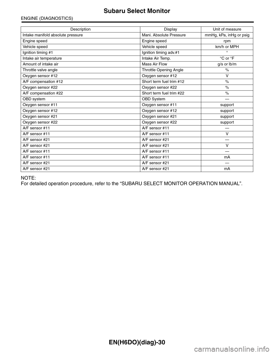
Subaru Select Monitor
ENGINE (DIAGNOSTICS)
NOTE:
For detailed operation procedure, refer to the “SUBARU SELECT MONITOR OPERATION MANUAL”.
Intake manifold absolute pressure Mani. Absolute Pressure mmHg, kPa, inHg or psig
Engine speed Engine speed rpm
Ve h i c l e s p e e d Ve h i c l e s p e e d k m / h o r M P H
Ignition timing #1 Ignition timing adv.#1 °
Intake air temperature Intake Air Temp. °C or °F
Amount of intake air Mass Air Flow g/s or lb/m
Throttle valve angle Throttle Opening Angle %
Oxygen sensor #12 Oxygen sensor #12 V
A/F compensation #12 Short term fuel trim #12 %
Oxygen sensor #22 Oxygen sensor #22 %
A/F compensation #22 Short term fuel trim #22 %
OBD system OBD System —
Oxygen sensor #11 Oxygen sensor #11 support
Oxygen sensor #12 Oxygen sensor #12 support
Oxygen sensor #21 Oxygen sensor #21 support
Oxygen sensor #22 Oxygen sensor #22 support
A/F sensor #11 A/F sensor #11 —
A/F sensor #11 A/F sensor #11 V
A/F sensor #21 A/F sensor #21 —
A/F sensor #21 A/F sensor #21 V
A/F sensor #11 A/F sensor #11 —
A/F sensor #11 A/F sensor #11 mA
A/F sensor #21 A/F sensor #21 —
A/F sensor #21 A/F sensor #21 mA
Description Display Unit of measure
Page 1192 of 2453
![SUBARU TRIBECA 2009 1.G Service Workshop Manual EN(H6DO)(diag)-31
Subaru Select Monitor
ENGINE (DIAGNOSTICS)
6. READ FREEZE FRAME DATA FOR ENGINE (OBD MODE)
1) On the «Main Menu» display screen, select the {Each System Check} and press the [YES] SUBARU TRIBECA 2009 1.G Service Workshop Manual EN(H6DO)(diag)-31
Subaru Select Monitor
ENGINE (DIAGNOSTICS)
6. READ FREEZE FRAME DATA FOR ENGINE (OBD MODE)
1) On the «Main Menu» display screen, select the {Each System Check} and press the [YES]](/manual-img/17/7322/w960_7322-1191.png)
EN(H6DO)(diag)-31
Subaru Select Monitor
ENGINE (DIAGNOSTICS)
6. READ FREEZE FRAME DATA FOR ENGINE (OBD MODE)
1) On the «Main Menu» display screen, select the {Each System Check} and press the [YES] key.
2) On the «System Selection Menu» display screen, select the {Engine} and press the [YES] key.
3) Press the [YES] key after the information of engine type has been displayed.
4) On the «Engine Diagnosis» display screen, select the {OBD System} and press the [YES] key.
5) On the «OBD Menu» display screen, select the {Freeze Frame Data} and press the [YES] key.
•A list of the support data is shown in the following table.
NOTE:
For detailed operation procedure, refer to the “SUBARU SELECT MONITOR OPERATION MANUAL”.
Description Display Unit of measure
DTC of freeze frame data Freeze frame data DTC
Air fuel ratio control system for bank 1 Fuel system for Bank1 —
Air fuel ratio control system for bank 2 Fuel system for Bank2 —
Engine load data Engine Load %
Engine coolant temperature signal Coolant Temp. °C or °F
Short term fuel trim by front oxygen (A/F) sensor (Bank 1) Short term fuel trim B1 %
Long term fuel trim by front oxygen (A/F) sensor (Bank 1) Long term fuel trim B1 %
Short term fuel trim by front oxygen (A/F) sensor (Bank 2) Short term fuel trim B2 %
Long term fuel trim by front oxygen (A/F) sensor (Bank 2) Long term fuel trim B2 %
Intake manifold absolute pressure signal Mani. Absolute Pressure mmHg, kPa, inHg or psig
Engine speed signal Engine Speed rpm
Ve h i c l e s p e e d s i g n a l Ve h i c l e S p e e d k m / h o r M P H
Ignition timing #1 Ignition timing adv. #1 °
Intake air temperature Intake Air Temp. °C
Amount of intake air Mass Air Flow g/s
Throttle valve angle Throttle Opening Angle %
Oxygen sensor #12 Oxygen sensor #12 V
A/F compensation #12 Short term fuel trim #12 %
Oxygen sensor #22 Oxygen sensor #22 V
A/F compensation #12 Short term fuel trim #22 %
Oxygen sensor #11 Oxygen sensor #11 support
Oxygen sensor #12 Oxygen sensor #12 support
Oxygen sensor #21 Oxygen sensor #21 support
Oxygen sensor #22 Oxygen sensor #22 support
Page 1199 of 2453
EN(H6DO)(diag)-38
Inspection Mode
ENGINE (DIAGNOSTICS)
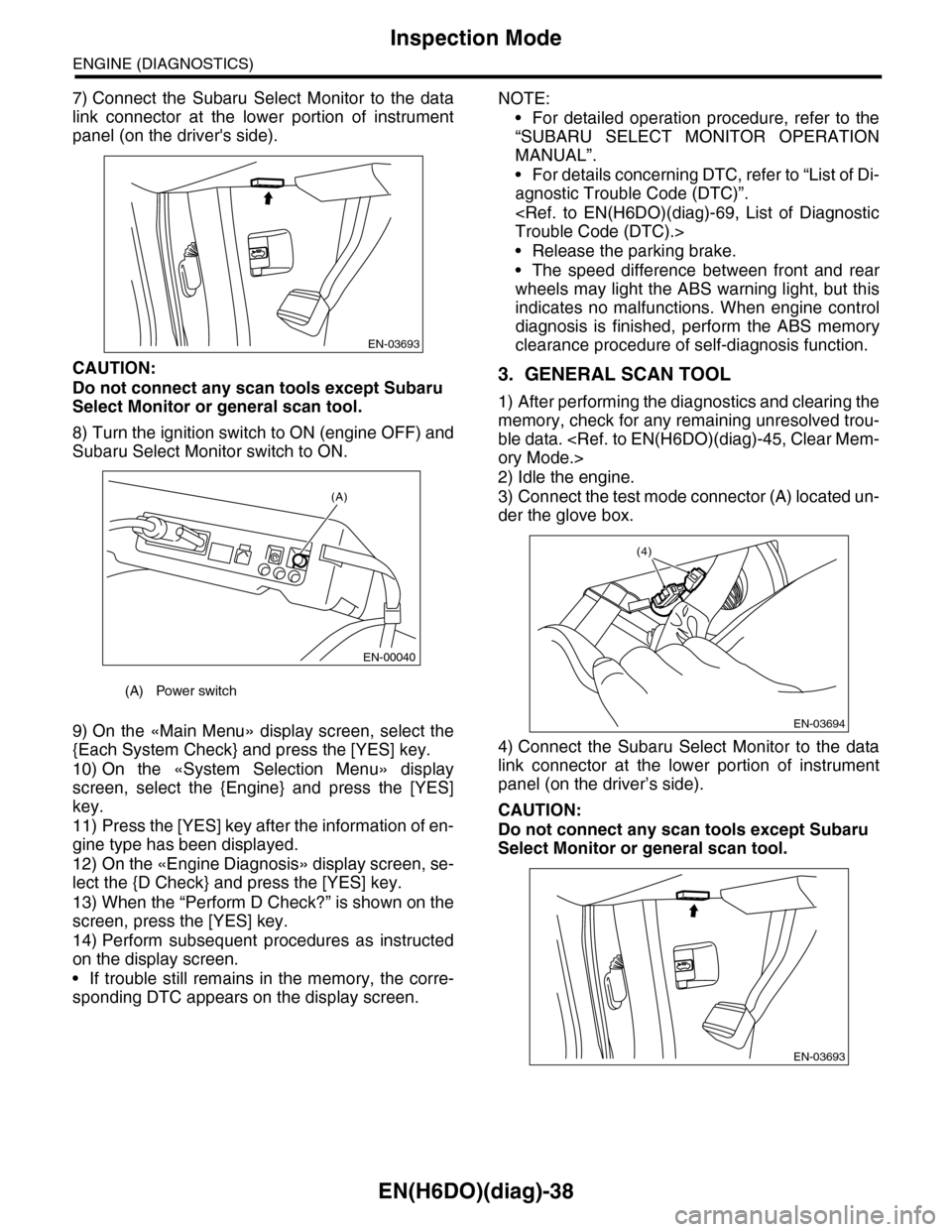
7) Connect the Subaru Select Monitor to the data
link connector at the lower portion of instrument
panel (on the driver's side).
CAUTION:
Do not connect any scan tools except Subaru
Select Monitor or general scan tool.
8) Turn the ignition switch to ON (engine OFF) and
Subaru Select Monitor switch to ON.
9) On the «Main Menu» display screen, select the
{Each System Check} and press the [YES] key.
10) On the «System Selection Menu» display
screen, select the {Engine} and press the [YES]
key.
11) Press the [YES] key after the information of en-
gine type has been displayed.
12) On the «Engine Diagnosis» display screen, se-
lect the {D Check} and press the [YES] key.
13) When the “Perform D Check?” is shown on the
screen, press the [YES] key.
14) Perform subsequent procedures as instructed
on the display screen.
•If trouble still remains in the memory, the corre-
sponding DTC appears on the display screen.
NOTE:
•For detailed operation procedure, refer to the
“SUBARU SELECT MONITOR OPERATION
MANUAL”.
•For details concerning DTC, refer to “List of Di-
agnostic Trouble Code (DTC)”.
•Release the parking brake.
•The speed difference between front and rear
wheels may light the ABS warning light, but this
indicates no malfunctions. When engine control
diagnosis is finished, perform the ABS memory
clearance procedure of self-diagnosis function.
3. GENERAL SCAN TOOL
1) After performing the diagnostics and clearing the
memory, check for any remaining unresolved trou-
ble data.
2) Idle the engine.
3) Connect the test mode connector (A) located un-
der the glove box.
4) Connect the Subaru Select Monitor to the data
link connector at the lower portion of instrument
panel (on the driver’s side).
CAUTION:
Do not connect any scan tools except Subaru
Select Monitor or general scan tool.
(A) Power switch
EN-03693
(A)
EN-00040
EN-03694
(4)
EN-03693
Page 1200 of 2453
EN(H6DO)(diag)-39
Inspection Mode
ENGINE (DIAGNOSTICS)
5) Start the engine.
NOTE:
Make sure the select lever is placed in “P” position
before starting.
6) Using the select lever, turn the “P” position
switch and the “N” position switch to ON.
7) Depress the brake pedal to turn brake switch
ON.
8) Keep the engine speed in 2,500 — 3,000 rpm
range for 40 seconds.
9) Shift the select lever in the “D” range and drive
the vehicle at 5 to 10 km/h (3 to 6 MPH).
NOTE:
•For AWD model, release the parking brake.
•The speed difference between front and rear
wheels may light the ABS warning light, but this in-
dicates no malfunctions. When engine control diag-
nosis is finished, perform the ABS memory
clearance procedure of self-diagnosis system.
10) Using the general scan tool, check DTC and
record the result(s).
NOTE:
•For detailed operation procedure, refer to the
general scan tool operation manual.
•For details concerning DTC, refer to “List of Diag-
nostic Trouble Code (DTC)”.
Page 1553 of 2453
EN(H6DO)(diag)-392
General Diagnostic Table
ENGINE (DIAGNOSTICS)
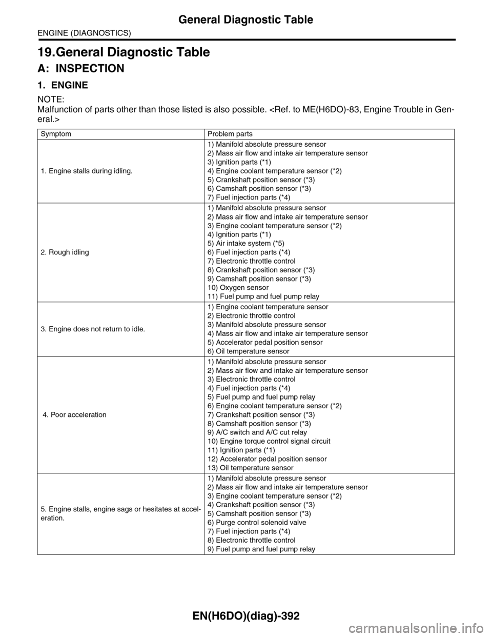
19.General Diagnostic Table
A: INSPECTION
1. ENGINE
NOTE:
Malfunction of parts other than those listed is also possible.
Symptom Problem parts
1. Engine stalls during idling.
1) Manifold absolute pressure sensor
2) Mass air flow and intake air temperature sensor
3) Ignition parts (*1)
4) Engine coolant temperature sensor (*2)
5) Crankshaft position sensor (*3)
6) Camshaft position sensor (*3)
7) Fuel injection parts (*4)
2. Rough idling
1) Manifold absolute pressure sensor
2) Mass air flow and intake air temperature sensor
3) Engine coolant temperature sensor (*2)
4) Ignition parts (*1)
5) Air intake system (*5)
6) Fuel injection parts (*4)
7) Electronic throttle control
8) Crankshaft position sensor (*3)
9) Camshaft position sensor (*3)
10) Oxygen sensor
11) Fuel pump and fuel pump relay
3. Engine does not return to idle.
1) Engine coolant temperature sensor
2) Electronic throttle control
3) Manifold absolute pressure sensor
4) Mass air flow and intake air temperature sensor
5) Accelerator pedal position sensor
6) Oil temperature sensor
4. Poor acceleration
1) Manifold absolute pressure sensor
2) Mass air flow and intake air temperature sensor
3) Electronic throttle control
4) Fuel injection parts (*4)
5) Fuel pump and fuel pump relay
6) Engine coolant temperature sensor (*2)
7) Crankshaft position sensor (*3)
8) Camshaft position sensor (*3)
9) A/C switch and A/C cut relay
10) Engine torque control signal circuit
11) Ignition parts (*1)
12) Accelerator pedal position sensor
13) Oil temperature sensor
5. Engine stalls, engine sags or hesitates at accel-
eration.
1) Manifold absolute pressure sensor
2) Mass air flow and intake air temperature sensor
3) Engine coolant temperature sensor (*2)
4) Crankshaft position sensor (*3)
5) Camshaft position sensor (*3)
6) Purge control solenoid valve
7) Fuel injection parts (*4)
8) Electronic throttle control
9) Fuel pump and fuel pump relay
Page 1554 of 2453
EN(H6DO)(diag)-393
General Diagnostic Table
ENGINE (DIAGNOSTICS)
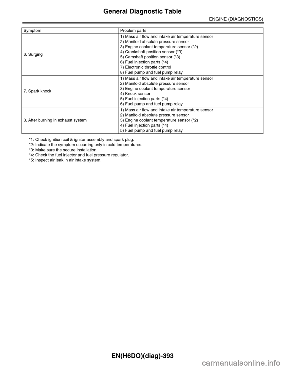
*1: Check ignition coil & ignitor assembly and spark plug.
*2: Indicate the symptom occurring only in cold temperatures.
*3: Make sure the secure installation.
*4: Check the fuel injector and fuel pressure regulator.
*5: Inspect air leak in air intake system.
6. Surging
1) Mass air flow and intake air temperature sensor
2) Manifold absolute pressure sensor
3) Engine coolant temperature sensor (*2)
4) Crankshaft position sensor (*3)
5) Camshaft position sensor (*3)
6) Fuel injection parts (*4)
7) Electronic throttle control
8) Fuel pump and fuel pump relay
7. Spark knock
1) Mass air flow and intake air temperature sensor
2) Manifold absolute pressure sensor
3) Engine coolant temperature sensor
4) Knock sensor
5) Fuel injection parts (*4)
6) Fuel pump and fuel pump relay
8. After burning in exhaust system
1) Mass air flow and intake air temperature sensor
2) Manifold absolute pressure sensor
3) Engine coolant temperature sensor (*2)
4) Fuel injection parts (*4)
5) Fuel pump and fuel pump relay
Symptom Problem parts
Page 1565 of 2453
FU(H6DO)-4
General Description
FUEL INJECTION (FUEL SYSTEMS)
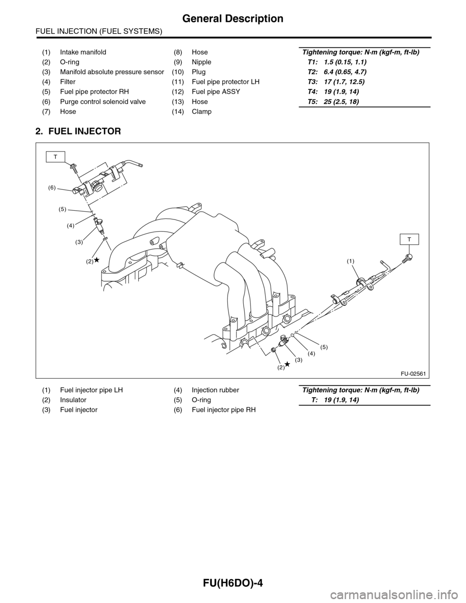
2. FUEL INJECTOR
(1) Intake manifold (8) HoseTightening torque: N·m (kgf-m, ft-lb)
(2) O-ring (9) NippleT1: 1.5 (0.15, 1.1)
(3) Manifold absolute pressure sensor (10) PlugT2: 6.4 (0.65, 4.7)
(4) Filter (11) Fuel pipe protector LHT3: 17 (1.7, 12.5)
(5) Fuel pipe protector RH (12) Fuel pipe ASSYT4: 19 (1.9, 14)
(6) Purge control solenoid valve (13) HoseT5: 25 (2.5, 18)
(7) Hose (14) Clamp
(1) Fuel injector pipe LH (4) Injection rubberTightening torque: N·m (kgf-m, ft-lb)
(2) Insulator (5) O-ringT: 19 (1.9, 14)
(3) Fuel injector (6) Fuel injector pipe RH
FU-02561
(6)
T
T
(5)
(4)
(3)
(2)
(2)(3)(4)(5)
(1)
Page 1576 of 2453
FU(H6DO)-15
Intake Manifold
FUEL INJECTION (FUEL SYSTEMS)
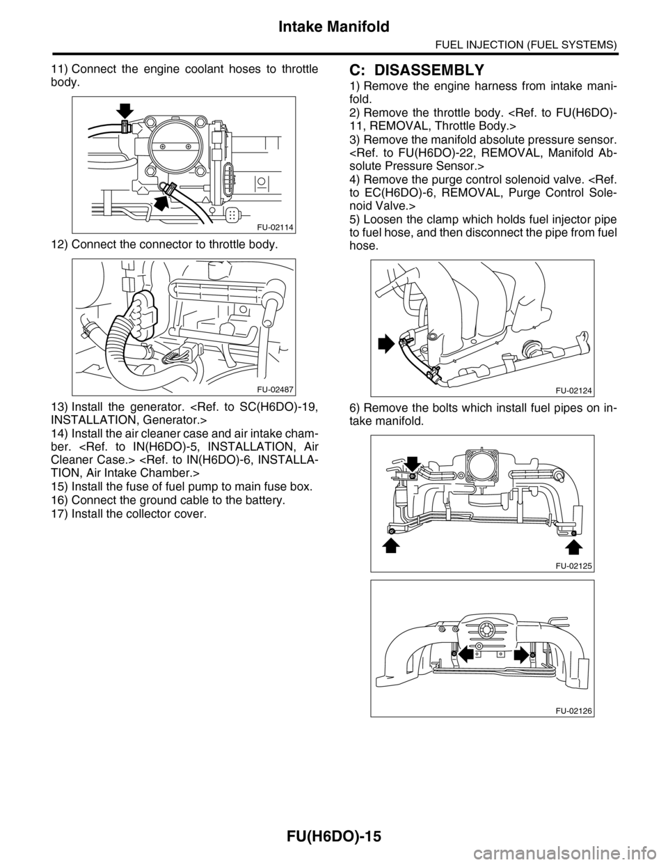
11) Connect the engine coolant hoses to throttle
body.
12) Connect the connector to throttle body.
13) Install the generator.
14) Install the air cleaner case and air intake cham-
ber.
15) Install the fuse of fuel pump to main fuse box.
16) Connect the ground cable to the battery.
17) Install the collector cover.
C: DISASSEMBLY
1) Remove the engine harness from intake mani-
fold.
2) Remove the throttle body.
3) Remove the manifold absolute pressure sensor.
4) Remove the purge control solenoid valve.
noid Valve.>
5) Loosen the clamp which holds fuel injector pipe
to fuel hose, and then disconnect the pipe from fuel
hose.
6) Remove the bolts which install fuel pipes on in-
take manifold.
FU-02114
FU-02487FU-02124
FU-02125
FU-02126