Page 1577 of 2453
FU(H6DO)-16
Intake Manifold
FUEL INJECTION (FUEL SYSTEMS)
D: ASSEMBLY
NOTE:
When assembling the nipple, apply liquid gasket.
Liquid gasket:
THREE BOND 1105 (Part No.004403010)
1) Tighten the bolts which install fuel pipes on in-
take manifold.
Tightening torque:
6.4 N·m (0.65 kgf-m, 4.7 ft-lb)
2) Connect the fuel injector pipe to fuel hose, and
tighten the clamp screw.
Tightening torque:
1.5 N·m (0.15 kgf-m, 1.1 ft-lb)
3) Install the purge control solenoid valve.
EC(H6DO)-6, INSTALLATION, Purge Control So-
lenoid Valve.>
4) Install the manifold absolute pressure sensor.
Absolute Pressure Sensor.>
5) Install the throttle body to intake manifold.
to FU(H6DO)-11, INSTALLATION, Throttle Body.>
6) Install the engine harness to the intake manifold.
E: INSPECTION
Make sure the fuel pipe and fuel hoses are not
damaged and the connections are tightened firmly.
FU-02125
FU-02126
FU-02124
Page 1583 of 2453
FU(H6DO)-22
Manifold Absolute Pressure Sensor
FUEL INJECTION (FUEL SYSTEMS)
9. Manifold Absolute Pressure
Sensor
A: REMOVAL
1) Remove the collector cover.
2) Disconnect the ground cable from battery.
3) Disconnect the connector from manifold abso-
lute pressure sensor (A), and remove the filter as-
sembly (B) from intake manifold.
4) Remove the manifold absolute pressure sensor
from intake manifold.
B: INSTALLATION
Install in the reverse order of removal.
Tightening torque:
6.4 N·m (0.65 kgf-m, 4.7 ft-lb)
FU-02131
(B)(A)
Page 1697 of 2453

GD(H6DO)-85
Diagnostic Trouble Code (DTC) Detecting Criteria
GENERAL DESCRIPTION
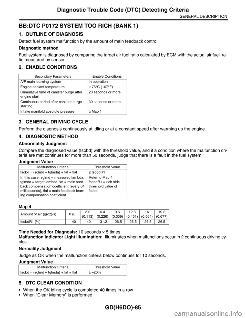
BB:DTC P0172 SYSTEM TOO RICH (BANK 1)
1. OUTLINE OF DIAGNOSIS
Detect fuel system malfunction by the amount of main feedback control.
Diagnostic method
Fuel system is diagnosed by comparing the target air fuel ratio calculated by ECM with the actual air fuel ra-
tio measured by sensor.
2. ENABLE CONDITIONS
3. GENERAL DRIVING CYCLE
Perform the diagnosis continuously at idling or at a constant speed after warming up the engine.
4. DIAGNOSTIC METHOD
Abnormality Judgment
Compare the diagnosed value (fsobd) with the threshold value, and if a condition where the malfunction cri-
teria are met continues for more than 50 seconds, judge that there is a fault in the fuel system.
Time Needed for Diagnosis: 10 seconds × 5 times
Malfunction Indicator Light Illumination: Illuminates when malfunctions occur in 2 continuous driving cy-
cles.
Normality Judgment
Judge as OK when the malfunction criteria below continues for 10 seconds.
5. DTC CLEAR CONDITION
•When the OK idling cycle is completed 40 times in a row
•When “Clear Memory” is performed
Secondary Parameters Enable Conditions
A/F main learning system In operation
Engine coolant temperature≥ 75°C (167°F)
Cumulative time of canister purge after
engine start
20 seconds or more
Continuous period after canister purge
starting
30 seconds or more
Intake manifold absolute pressure≥ Map 1
Judgment Value
Malfunction Criteria Threshold Value
fsobd = (sglmd – tglmda) + faf + flaf≤ fsobdR1
In this case: sglmd = measured lambda,
tglmda = target lambda, faf = main feed-
back compensation coefficient (every 64
milliseconds), flaf = main feedback learn-
ing compensation coefficient
Refer to Map 4.
fsobdR1 = rich side
threshold value of
fsobd
Map 4
Amount of air (g(oz)/s) 0 (0)3.2
(0.113)
6.4
(0.226)
9.6
(0.339)
12.8
(0.451)
16
(0.564)
19.2
(0.677)
fsobdR1 (%) –40 –40 –31.2 –26.5 –26.5 –26.5 26.5
Judgment Value
Malfunction Criteria Threshold Value
fsobd = (sglmd – tglmda) + faf + flaf≥ –20%
Page 1734 of 2453

GD(H6DO)-122
Diagnostic Trouble Code (DTC) Detecting Criteria
GENERAL DESCRIPTION
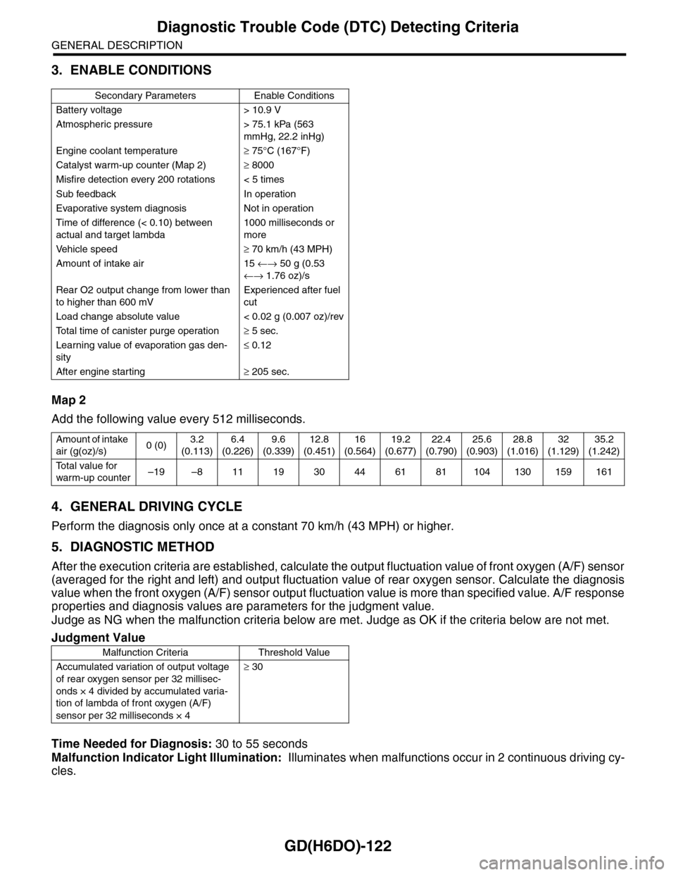
3. ENABLE CONDITIONS
Map 2
Add the following value every 512 milliseconds.
4. GENERAL DRIVING CYCLE
Perform the diagnosis only once at a constant 70 km/h (43 MPH) or higher.
5. DIAGNOSTIC METHOD
After the execution criteria are established, calculate the output fluctuation value of front oxygen (A/F) sensor
(averaged for the right and left) and output fluctuation value of rear oxygen sensor. Calculate the diagnosis
value when the front oxygen (A/F) sensor output fluctuation value is more than specified value. A/F response
properties and diagnosis values are parameters for the judgment value.
Judge as NG when the malfunction criteria below are met. Judge as OK if the criteria below are not met.
Time Needed for Diagnosis: 30 to 55 seconds
Malfunction Indicator Light Illumination: Illuminates when malfunctions occur in 2 continuous driving cy-
cles.
Secondary Parameters Enable Conditions
Battery voltage > 10.9 V
Atmospheric pressure > 75.1 kPa (563
mmHg, 22.2 inHg)
Engine coolant temperature≥ 75°C (167°F)
Catalyst warm-up counter (Map 2)≥ 8000
Misfire detection every 200 rotations < 5 times
Sub feedback In operation
Evaporative system diagnosis Not in operation
Time of difference (< 0.10) between
actual and target lambda
1000 milliseconds or
more
Ve h i c l e s p e e d≥ 70 km/h (43 MPH)
Amount of intake air 15 ←→ 50 g (0.53
←→ 1.76 oz)/s
Rear O2 output change from lower than
to higher than 600 mV
Experienced after fuel
cut
Load change absolute value < 0.02 g (0.007 oz)/rev
To t a l t i m e o f c a n i s t e r p u r g e o p e r a t i o n≥ 5 sec.
Learning value of evaporation gas den-
sity
≤ 0.12
After engine starting≥ 205 sec.
Amount of intake
air (g(oz)/s)0 (0)3.2
(0.113)
6.4
(0.226)
9.6
(0.339)
12.8
(0.451)
16
(0.564)
19.2
(0.677)
22.4
(0.790)
25.6
(0.903)
28.8
(1.016)
32
(1.129)
35.2
(1.242)
To t a l v a l u e f o r
warm-up counter–19 –8 11 19 30 44 61 81 104 130 159 161
Judgment Value
Malfunction Criteria Threshold Value
Accumulated variation of output voltage
of rear oxygen sensor per 32 millisec-
onds × 4 divided by accumulated varia-
tion of lambda of front oxygen (A/F)
sensor per 32 milliseconds × 4
≥ 30
Page 1961 of 2453
SC(H6DO)-3
General Description
STARTING/CHARGING SYSTEMS
B: COMPONENT
1. STARTER
(1) Front bracket (12) Wave washer (23) Space ring
(2) Front bearing (13) Internal gear (24) Snap ring
(3) Plunger (14) Washer (25) End frame cover
(4) Snap ring (15) Shaft (26) Plunger spring
(5) Stopper (16) Planetary gear (27) Magnet switch
(6) Overrunning clutch (17) Armature plate
(7) Snap ring (18) YokeTightening torque: N·m (kgf-m, ft-lb)
(8) Washer (19) ArmatureT1: 1.4 (0.14, 1.03)
(9) Lever (20) Brush holder ASSYT2: 6 (0.6, 4.4)
(10) Oilless bearing (21) End frameT3: 7.5 (0.8, 5.5)
(11) Shock absorber bearing (22) Rear bearingT4: 10 (1.0, 7.4)
SC-02108
T3
T1
T2
(1)
(2)
T4
(4)(21)
(22)
(23)
(24)
(25)(5)(6)
(7)
(8)
(15)
(14)(13)
(12)(11)
(10)(9)
(3)
(26)
(27)
(16)(17)
(18)
(19)
(20)
Page 1966 of 2453
SC(H6DO)-8
Starter
STARTING/CHARGING SYSTEMS
14) Remove the shaft assembly, overrunning
clutch and lever from front bracket as a unit.
15) Remove the overrunning clutch from shaft as-
sembly as follows:
(1) Remove the stopper from snap ring by light-
ly tapping the stopper with an appropriate tool
(such as a fit socket wrench).
(2) Remove the snap ring, stopper and clutch
from shaft.
16) Remove the snap ring.
17) Remove the shock absorber bearing, wave
washer and internal gear from shaft.
18) Remove the front bearing from front bracket.
(1) Set an appropriate tool (φ13 mm) to front
bearing.
(2) Using a press, remove the front bearing.
(A) Front bracket
(B) Lever
(C) Shaft ASSY
(A) Socket wrench
(B) Snap ring
(C) Shaft
(D) Stopper
SC-02052
(B)
(A)
(C)
SC-00014
(A)
(B)
(C)(D)
(A) Shock absorber bearing
(B) Wave washer
(C) Internal gear
SC-02053
SC-02054
(C)
(A)
(B)
SC-02055
Page 1967 of 2453

SC(H6DO)-9
Starter
STARTING/CHARGING SYSTEMS
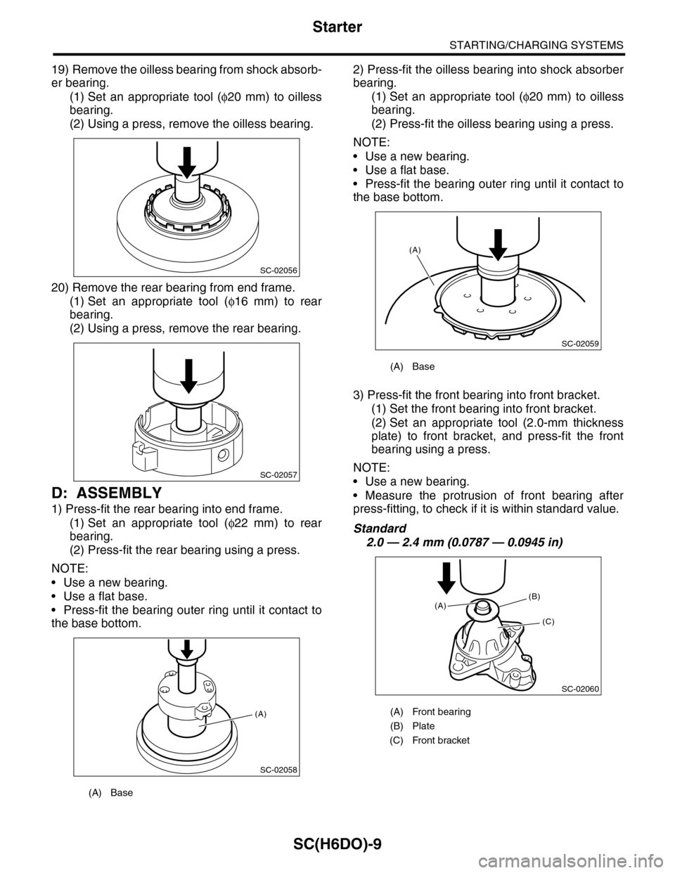
19) Remove the oilless bearing from shock absorb-
er bearing.
(1) Set an appropriate tool (φ20 mm) to oilless
bearing.
(2) Using a press, remove the oilless bearing.
20) Remove the rear bearing from end frame.
(1) Set an appropriate tool (φ16 mm) to rear
bearing.
(2) Using a press, remove the rear bearing.
D: ASSEMBLY
1) Press-fit the rear bearing into end frame.
(1) Set an appropriate tool (φ22 mm) to rear
bearing.
(2) Press-fit the rear bearing using a press.
NOTE:
•Use a new bearing.
•Use a flat base.
•Press-fit the bearing outer ring until it contact to
the base bottom.
2) Press-fit the oilless bearing into shock absorber
bearing.
(1) Set an appropriate tool (φ20 mm) to oilless
bearing.
(2) Press-fit the oilless bearing using a press.
NOTE:
•Use a new bearing.
•Use a flat base.
•Press-fit the bearing outer ring until it contact to
the base bottom.
3) Press-fit the front bearing into front bracket.
(1) Set the front bearing into front bracket.
(2) Set an appropriate tool (2.0-mm thickness
plate) to front bracket, and press-fit the front
bearing using a press.
NOTE:
•Use a new bearing.
•Measure the protrusion of front bearing after
press-fitting, to check if it is within standard value.
Standard
2.0 — 2.4 mm (0.0787 — 0.0945 in)
(A) Base
SC-02056
SC-02057
SC-02058
(A)
(A) Base
(A) Front bearing
(B) Plate
(C) Front bracket
SC-02059
(A)
SC-02060
(B)
(C)
(A)
Page 1968 of 2453

SC(H6DO)-10
Starter
STARTING/CHARGING SYSTEMS
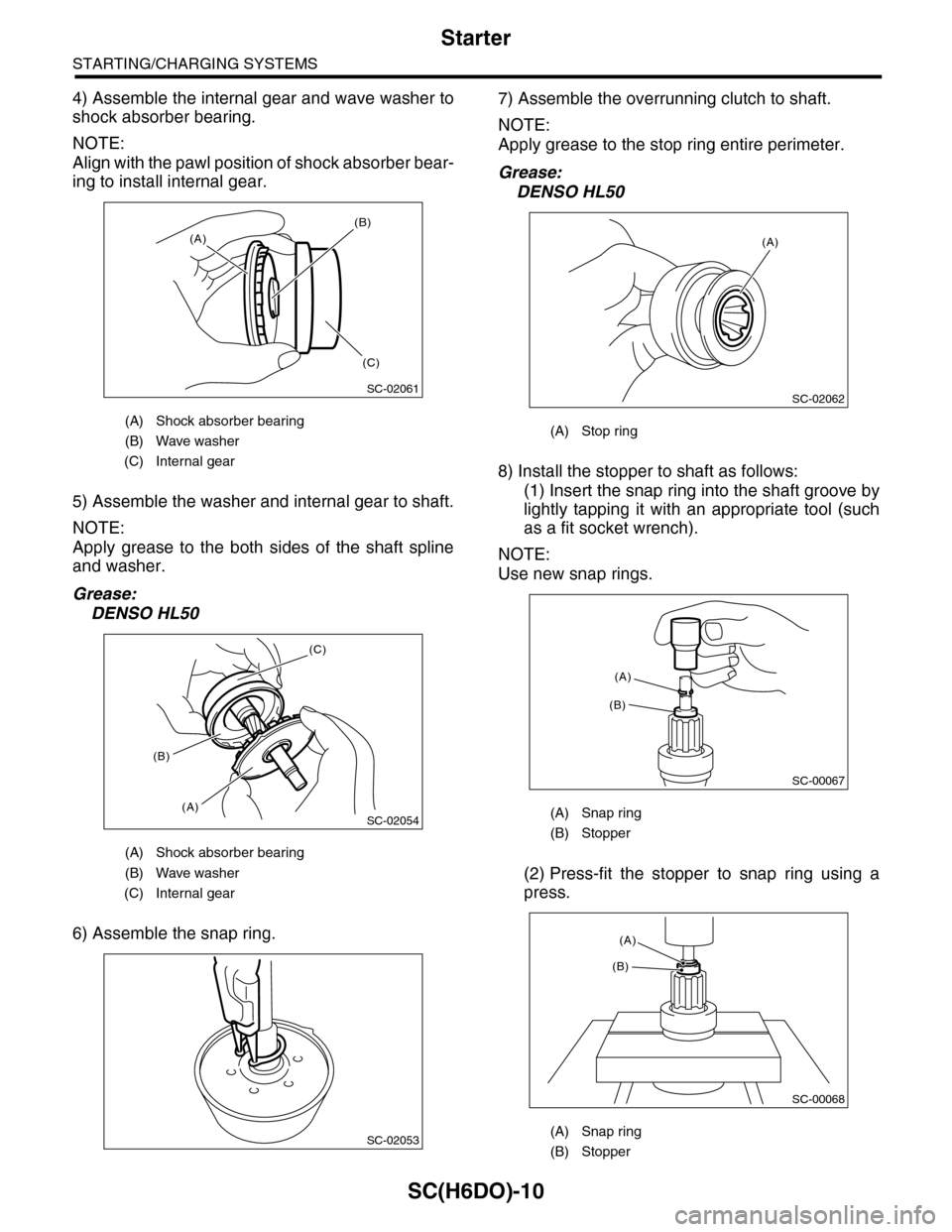
4) Assemble the internal gear and wave washer to
shock absorber bearing.
NOTE:
Align with the pawl position of shock absorber bear-
ing to install internal gear.
5) Assemble the washer and internal gear to shaft.
NOTE:
Apply grease to the both sides of the shaft spline
and washer.
Grease:
DENSO HL50
6) Assemble the snap ring.
7) Assemble the overrunning clutch to shaft.
NOTE:
Apply grease to the stop ring entire perimeter.
Grease:
DENSO HL50
8) Install the stopper to shaft as follows:
(1) Insert the snap ring into the shaft groove by
lightly tapping it with an appropriate tool (such
as a fit socket wrench).
NOTE:
Use new snap rings.
(2) Press-fit the stopper to snap ring using a
press.
(A) Shock absorber bearing
(B) Wave washer
(C) Internal gear
(A) Shock absorber bearing
(B) Wave washer
(C) Internal gear
SC-02061
(A)
(B)
(C)
SC-02054
(C)
(A)
(B)
SC-02053
(A) Stop ring
(A) Snap ring
(B) Stopper
(A) Snap ring
(B) Stopper
SC-02062
(A)
SC-00067
(B)
(A)
SC-00068
(A)
(B)