2009 SUBARU TRIBECA system abs
[x] Cancel search: system absPage 1049 of 2453
VDC(diag)-57
Diagnostic Procedure with Diagnostic Trouble Code (DTC)
VEHICLE DYNAMICS CONTROL (VDC) (DIAGNOSTICS)
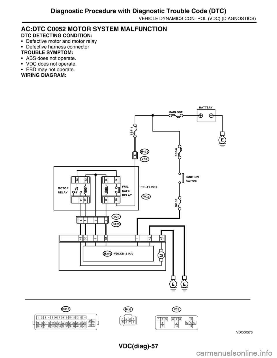
AC:DTC C0052 MOTOR SYSTEM MALFUNCTION
DTC DETECTING CONDITION:
•Defective motor and motor relay
•Defective harness connector
TROUBLE SYMPTOM:
•ABS does not operate.
•VDC does not operate.
•EBD may not operate.
WIRING DIAGRAM:
B310
B423
VC1
B423
VC1
VC2
E
246
2314
B310 VDCCM & H/U
1234
1516171819202122232425262728293031323334353637383940414245464344568910 11 12 13 147
VDC00373
1314
1211
421453031
E
MAIN SBF
SBF-6
NO.33
E
BATTERY
IGNITIONSWITCH
MOTORRELAY
RELAY BOXFAILSAFERELAY
B423
34561278
VC2
12345
678910121311
14
SBF-1
M
96
108
5
Page 1052 of 2453
VDC(diag)-60
Diagnostic Procedure with Diagnostic Trouble Code (DTC)
VEHICLE DYNAMICS CONTROL (VDC) (DIAGNOSTICS)
AD:DTC C0052 MOTOR/MOTOR RELAY SYSTEM SHORT
NOTE:
For the diagnostic procedure, refer to DTC C0052 “FAIL SAFE RELAY SYSTEM SHORT”.
Trouble Code (DTC).>
AE:DTC C0052 MOTOR FAIL SAFE RELAY SHORT CIRCUIT
DTC DETECTING CONDITION:
•Defective motor relay
•Fail safe relay malfunction
•Defective harness connector
TROUBLE SYMPTOM:
•ABS does not operate.
•VDC does not operate.
•EBD may not operate.
Page 1056 of 2453
VDC(diag)-64
Diagnostic Procedure with Diagnostic Trouble Code (DTC)
VEHICLE DYNAMICS CONTROL (VDC) (DIAGNOSTICS)
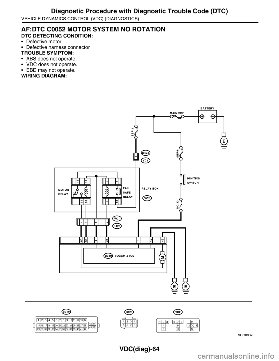
AF:DTC C0052 MOTOR SYSTEM NO ROTATION
DTC DETECTING CONDITION:
•Defective motor
•Defective harness connector
TROUBLE SYMPTOM:
•ABS does not operate.
•VDC does not operate.
•EBD may not operate.
WIRING DIAGRAM:
B310
B423
VC1
B423
VC1
VC2
E
246
2314
B310 VDCCM & H/U
1234
1516171819202122232425262728293031323334353637383940414245464344568910 11 12 13 147
VDC00373
1314
1211
421453031
E
MAIN SBF
SBF-6
NO.33
E
BATTERY
IGNITIONSWITCH
MOTORRELAY
RELAY BOXFAILSAFERELAY
B423
34561278
VC2
12345
678910121311
14
SBF-1
M
96
108
5
Page 1063 of 2453
VDC(diag)-71
Diagnostic Procedure with Diagnostic Trouble Code (DTC)
VEHICLE DYNAMICS CONTROL (VDC) (DIAGNOSTICS)
AL:DTC C0057 ECM COMMUNICATION
DTC DETECTING CONDITION:
No CAN signal from ECM.
TROUBLE SYMPTOM:
VDC does not operate.
AM:DTC C0057 AT COMMUNICATION
DTC DETECTING CONDITION:
No CAN signal from TCM.
TROUBLE SYMPTOM:
•ABS does not operate.
•VDC does not operate.
Step Check Yes No
1CHECK LAN SYSTEM.
Perfor m the diagnosis for LAN system.
Tr o u b l e C o d e ( D T C ) . >
Is there any fault in LAN sys-
tem?
Pe r for m t h e d ia g -
nosis according to
DTC for LAN sys-
tem.
Go to step 2.
2CHECK POOR CONTACT OF CONNEC-
TORS.
Is there poor contact in ECM
connector?
Repair the con-
nector.
Go to step 3.
3CHECK ECM.Is ECM normal? Go to step 4.Replace the ECM.
4CHECK THE VDCCM&H/U.
1) Connect all the connectors.
2) Erase the memory.
3) Perform the inspection mode.
4) Read the DTC.
Is the same DTC displayed? Replace the
VDCCM&H/U.
ule & Hydraulic
Control Unit
(VDCCM&H/U).>
Go to step 5.
5CHECK OTHER DTC DETECTION.Is any other DTC displayed? Perform the diag-
nosis according to
DTC.
Te m p o r a r y p o o r
contact occurs.
Step Check Yes No
1CHECK LAN SYSTEM.
Perfor m the diagnosis for LAN system.
Tr o u b l e C o d e ( D T C ) . >
Is there any fault in LAN sys-
tem?
Pe r for m t h e d ia g -
nosis according to
DTC for LAN sys-
tem.
Go to step 2.
2CHECK POOR CONTACT OF CONNEC-
TORS.
Is there poor contact in TCM
connector?
Repair the con-
nector.
Go to step 3.
3CHECK TCM.Is the TCM normal? Go to step 4.Replace the TCM.
trol Module
(TCM).>
4CHECK THE VDCCM&H/U.
1) Connect all the connectors.
2) Erase the memory.
3) Perform the inspection mode.
4) Read the DTC.
Is the same DTC displayed? Replace the
VDCCM&H/U.
Go to step 5.
5CHECK OTHER DTC DETECTION.Is any other DTC displayed? Perform the diag-
nosis according to
DTC.
Te m p o r a r y p o o r
contact occurs.
Page 1064 of 2453
VDC(diag)-72
Diagnostic Procedure with Diagnostic Trouble Code (DTC)
VEHICLE DYNAMICS CONTROL (VDC) (DIAGNOSTICS)
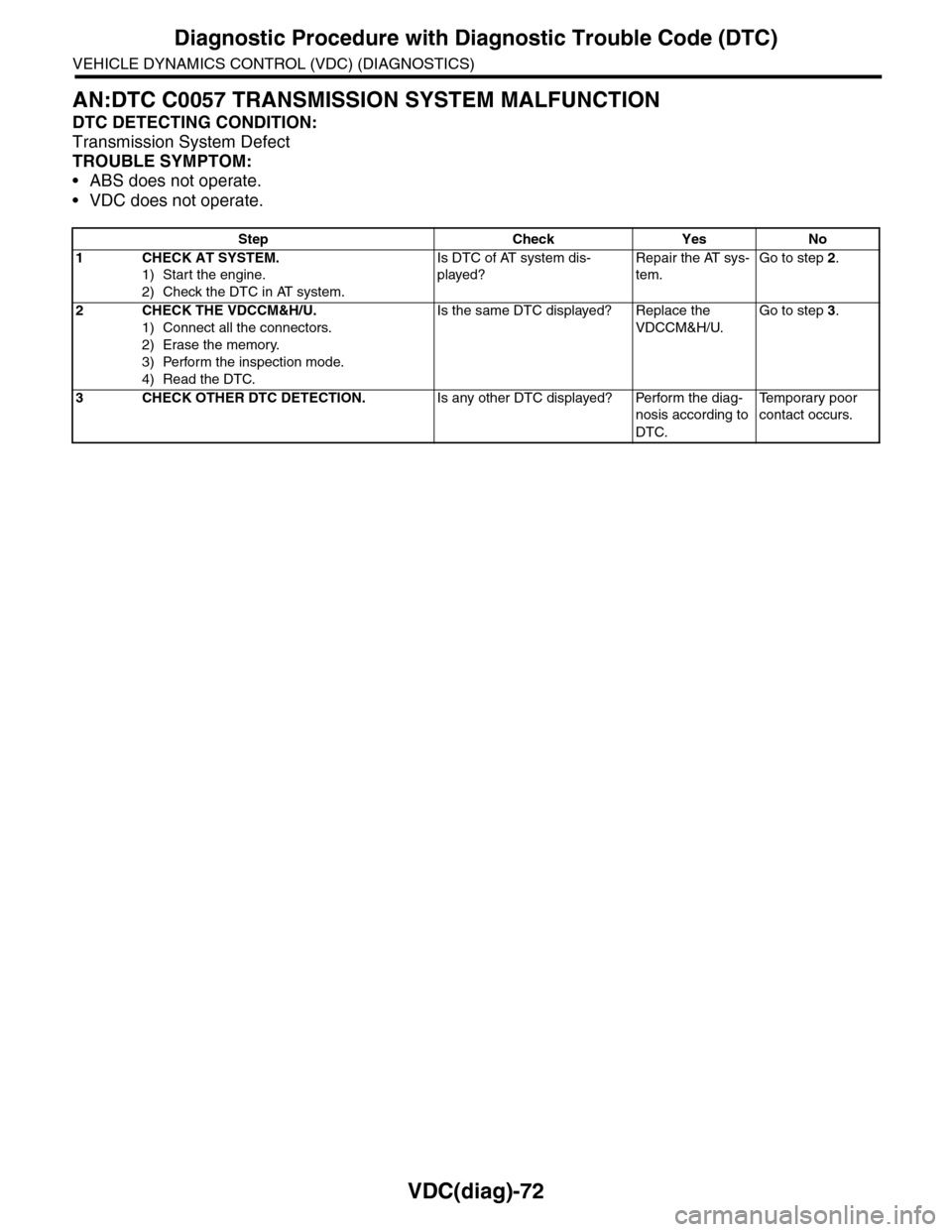
AN:DTC C0057 TRANSMISSION SYSTEM MALFUNCTION
DTC DETECTING CONDITION:
Transmission System Defect
TROUBLE SYMPTOM:
•ABS does not operate.
•VDC does not operate.
Step Check Yes No
1CHECK AT SYSTEM.
1) Start the engine.
2) Check the DTC in AT system.
Is DTC of AT system dis-
played?
Repair the AT sys-
tem.
Go to step 2.
2CHECK THE VDCCM&H/U.
1) Connect all the connectors.
2) Erase the memory.
3) Perform the inspection mode.
4) Read the DTC.
Is the same DTC displayed? Replace the
VDCCM&H/U.
Go to step 3.
3CHECK OTHER DTC DETECTION.Is any other DTC displayed? Perform the diag-
nosis according to
DTC.
Te m p o r a r y p o o r
contact occurs.
Page 1081 of 2453
VDC(diag)-89
General Diagnostic Table
VEHICLE DYNAMICS CONTROL (VDC) (DIAGNOSTICS)
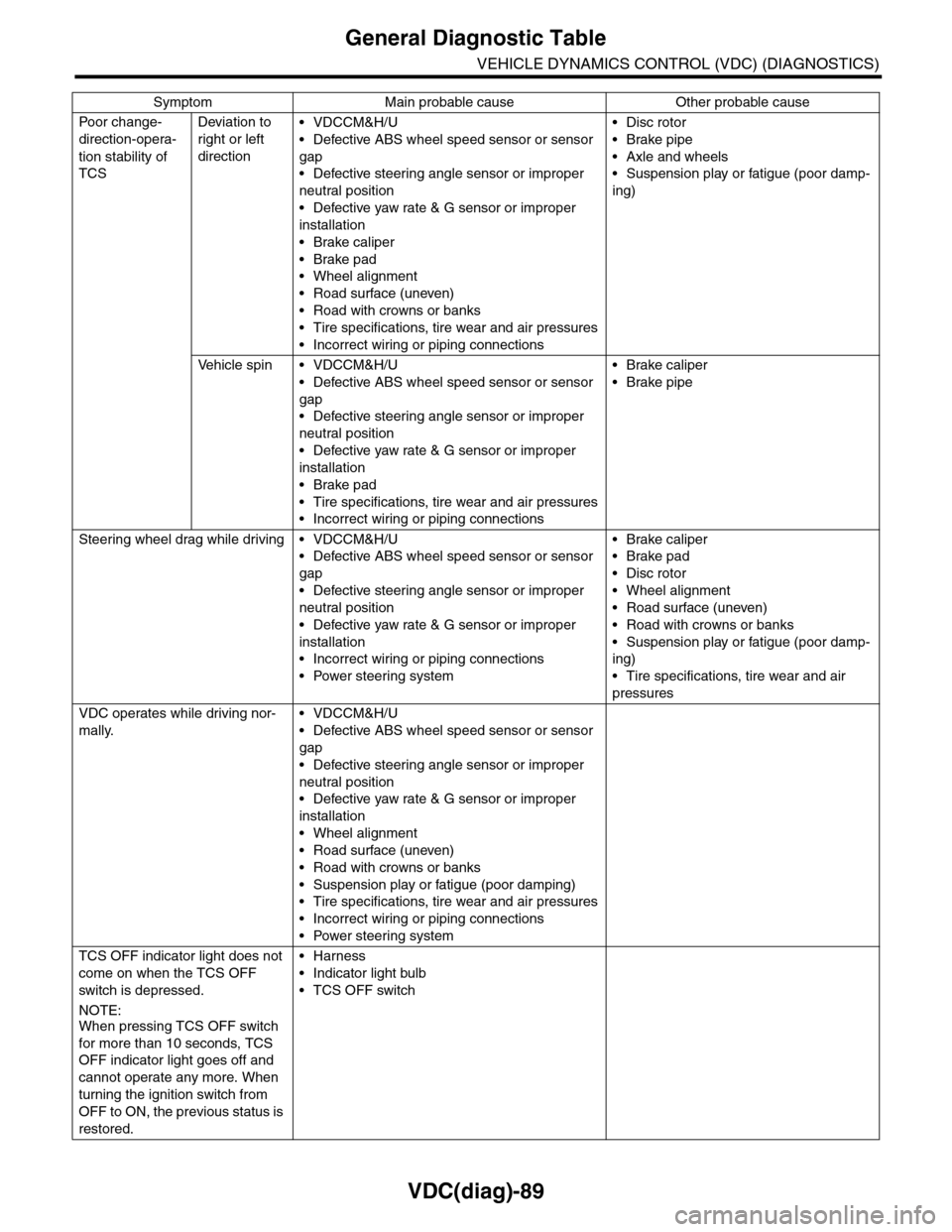
Po or ch a ng e -
direction-opera-
tion stability of
TCS
Deviation to
right or left
direction
•VDCCM&H/U
•Defective ABS wheel speed sensor or sensor
gap
•Defective steering angle sensor or improper
neutral position
•Defective yaw rate & G sensor or improper
installation
•Brake caliper
•Brake pad
•Wheel alignment
•Road surface (uneven)
•Road with crowns or banks
•Tire specifications, tire wear and air pressures
•Incorrect wiring or piping connections
•Disc rotor
•Brake pipe
•Axle and wheels
•Suspension play or fatigue (poor damp-
ing)
Ve h i c l e s p i n • V D C C M & H / U
•Defective ABS wheel speed sensor or sensor
gap
•Defective steering angle sensor or improper
neutral position
•Defective yaw rate & G sensor or improper
installation
•Brake pad
•Tire specifications, tire wear and air pressures
•Incorrect wiring or piping connections
•Brake caliper
•Brake pipe
Steering wheel drag while driving • VDCCM&H/U
•Defective ABS wheel speed sensor or sensor
gap
•Defective steering angle sensor or improper
neutral position
•Defective yaw rate & G sensor or improper
installation
•Incorrect wiring or piping connections
•Power steering system
•Brake caliper
•Brake pad
•Disc rotor
•Wheel alignment
•Road surface (uneven)
•Road with crowns or banks
•Suspension play or fatigue (poor damp-
ing)
•Tire specifications, tire wear and air
pressures
VDC operates while driving nor-
mally.
•VDCCM&H/U
•Defective ABS wheel speed sensor or sensor
gap
•Defective steering angle sensor or improper
neutral position
•Defective yaw rate & G sensor or improper
installation
•Wheel alignment
•Road surface (uneven)
•Road with crowns or banks
•Suspension play or fatigue (poor damping)
•Tire specifications, tire wear and air pressures
•Incorrect wiring or piping connections
•Power steering system
TCS OFF indicator light does not
come on when the TCS OFF
switch is depressed.
NOTE:When pressing TCS OFF switch
for more than 10 seconds, TCS
OFF indicator light goes off and
cannot operate any more. When
turning the ignition switch from
OFF to ON, the previous status is
restored.
•Harness
•Indicator light bulb
•TCS OFF switch
Symptom Main probable cause Other probable cause
Page 1089 of 2453
VDC-8
VDC Control Module & Hydraulic Control Unit (VDCCM&H/U)
VEHICLE DYNAMICS CONTROL (VDC)
4) Connect the VDCCM&H/U connectors.
NOTE:
•Be sure to remove all foreign matter from inside
the connector before connecting.
•Make sure the VDCCM&H/U connector is se-
curely locked.
5) Bleed air from the brake system.
C: INSPECTION
1) Check the condition of connection and settle-
ment of connector.
2) Check the mark used for VDCCM&H/U identifi-
cation.
Refer to “SPECIFICATION” for the identification
mark.
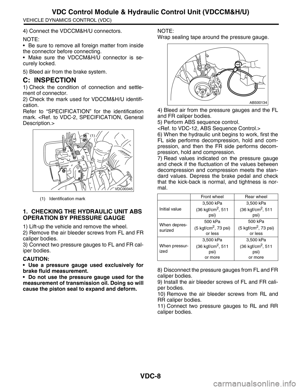
1. CHECKING THE HYDRAULIC UNIT ABS
OPERATION BY PRESSURE GAUGE
1) Lift-up the vehicle and remove the wheel.
2) Remove the air bleeder screws from FL and FR
caliper bodies.
3) Connect two pressure gauges to FL and FR cal-
iper bodies.
CAUTION:
•Use a pressure gauge used exclusively for
brake fluid measurement.
•Do not use the pressure gauge used for the
measurement of transmission oil. Doing so will
cause the piston seal to expand and deform.
NOTE:
Wrap sealing tape around the pressure gauge.
4) Bleed air from the pressure gauges and the FL
and FR caliper bodies.
5) Perform ABS sequence control.
6) When the hydraulic unit begins to work, first the
FL side performs decompression, hold and com-
pression, and then the FR side performs decom-
pression, hold and compression.
7) Read values indicated on the pressure gauge
and check if the fluctuation of the values between
decompression and compression meets the stan-
dard values. Depress the brake pedal and check
that the kick-back is normal, and tightness is nor-
mal.
8) Disconnect the pressure gauges from FL and FR
caliper bodies.
9) Install the air bleeder screws of FL and FR cali-
per bodies.
10) Remove the air bleeder screws from RL and
RR caliper bodies.
11) Connect two pressure gauges to RL and RR
caliper bodies.
(1) Identification mark
VDC00345
(1)
Front wheelRear wheel
Initial value
3,500 kPa
(36 kgf/cm2, 511
psi)
3,500 kPa
(36 kgf/cm2, 511
psi)
When depres-
surized
500 kPa
(5 kgf/cm2, 73 psi)
or less
500 kPa
(5 kgf/cm2, 73 psi)
or less
When pressur-
ized
3,500 kPa
(36 kgf/cm2, 511
psi)
or more
3,500 kPa
(36 kgf/cm2, 511
psi)
or more
ABS00134
Page 1090 of 2453
VDC-9
VDC Control Module & Hydraulic Control Unit (VDCCM&H/U)
VEHICLE DYNAMICS CONTROL (VDC)
12) Bleed air from the brake system.
13) Bleed air from RL and RR caliper bodies, and
pressure gauge.
14) Perform ABS sequence control.
15) When the hydraulic unit begins to work, first the
RR side performs decompression, hold and com-
pression, and then the RL side performs decom-
pression, hold and compression.
16) Read values indicated on the pressure gauge
and check if the fluctuation of the values between
decompression and compression meets specifica-
tion. Depress the brake pedal and check that the
kick-back is normal, and tightness is normal.
17) Disconnect the pressure gauge from the RL
and RR caliper bodies.
18) Install the air bleeder screws of RL and RR cal-
iper bodies.
19) Bleed air from the brake system.
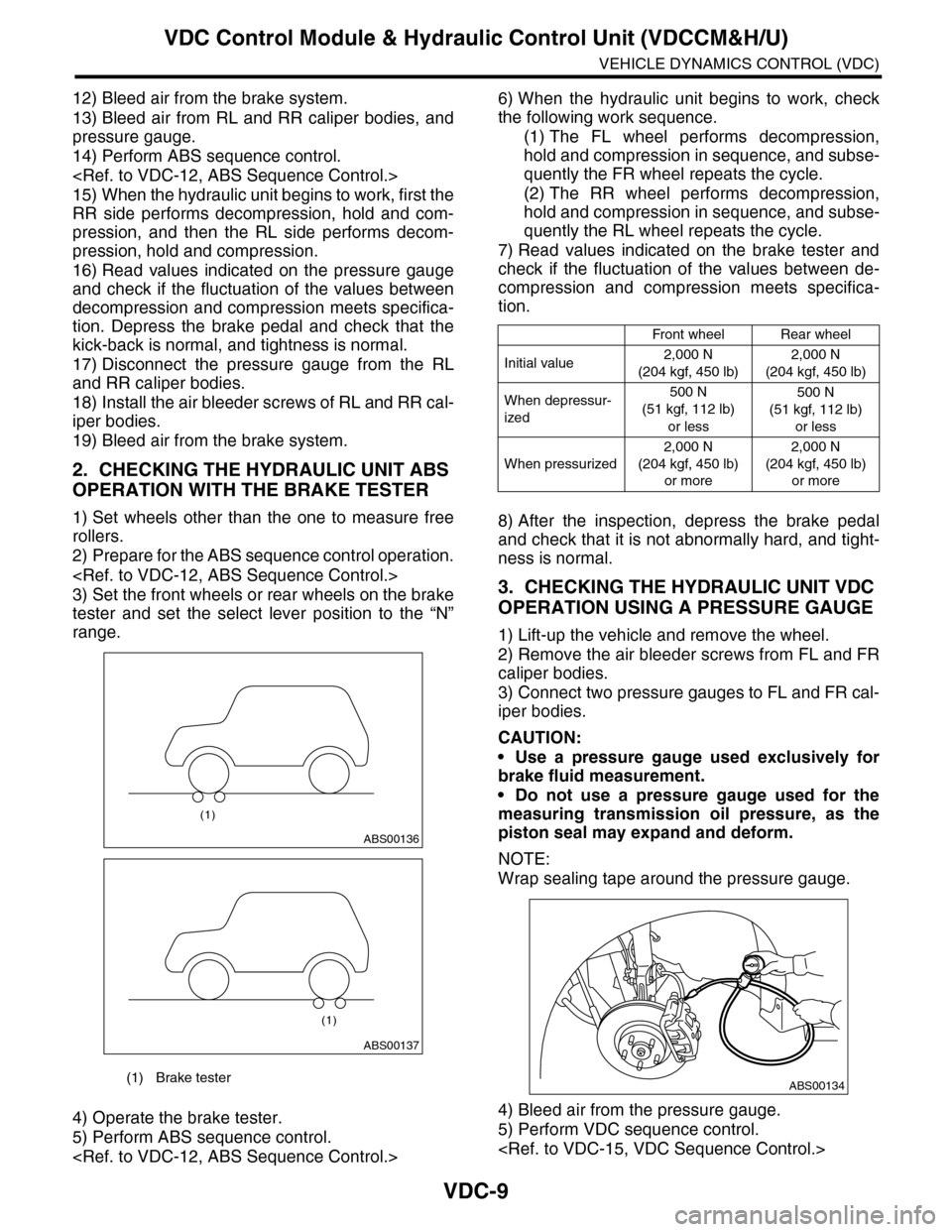
2. CHECKING THE HYDRAULIC UNIT ABS
OPERATION WITH THE BRAKE TESTER
1) Set wheels other than the one to measure free
rollers.
2) Prepare for the ABS sequence control operation.
3) Set the front wheels or rear wheels on the brake
tester and set the select lever position to the “N”
range.
4) Operate the brake tester.
5) Perform ABS sequence control.
6) When the hydraulic unit begins to work, check
the following work sequence.
(1) The FL wheel performs decompression,
hold and compression in sequence, and subse-
quently the FR wheel repeats the cycle.
(2) The RR wheel performs decompression,
hold and compression in sequence, and subse-
quently the RL wheel repeats the cycle.
7) Read values indicated on the brake tester and
check if the fluctuation of the values between de-
compression and compression meets specifica-
tion.
8) After the inspection, depress the brake pedal
and check that it is not abnormally hard, and tight-
ness is normal.
3. CHECKING THE HYDRAULIC UNIT VDC
OPERATION USING A PRESSURE GAUGE
1) Lift-up the vehicle and remove the wheel.
2) Remove the air bleeder screws from FL and FR
caliper bodies.
3) Connect two pressure gauges to FL and FR cal-
iper bodies.
CAUTION:
•Use a pressure gauge used exclusively for
brake fluid measurement.
•Do not use a pressure gauge used for the
measuring transmission oil pressure, as the
piston seal may expand and deform.
NOTE:
Wrap sealing tape around the pressure gauge.
4) Bleed air from the pressure gauge.
5) Perform VDC sequence control.
(1) Brake tester
ABS00136
(1)
ABS00137
(1)
Front wheelRear wheel
Initial value2,000 N
(204 kgf, 450 lb)
2,000 N
(204 kgf, 450 lb)
When depressur-
ized
500 N
(51 kgf, 112 lb)
or less
500 N
(51 kgf, 112 lb)
or less
When pressurized
2,000 N
(204 kgf, 450 lb)
or more
2,000 N
(204 kgf, 450 lb)
or more
ABS00134