2009 SUBARU TRIBECA light
[x] Cancel search: lightPage 2266 of 2453
CS-14
AT Shift Lock Control System
CONTROL SYSTEMS
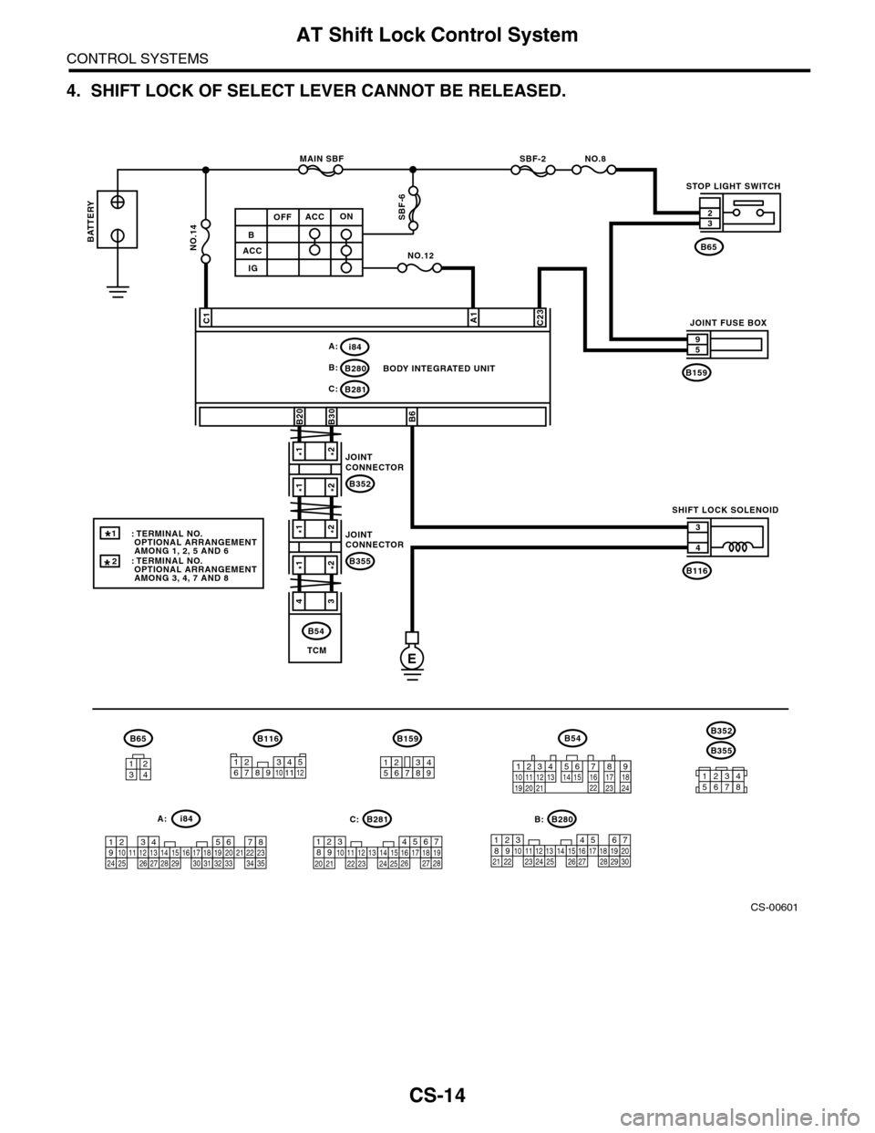
4. SHIFT LOCK OF SELECT LEVER CANNOT BE RELEASED.
CS-00601
NO.8
E
B280B:
B281C:
C23C1
B6
B
ACC
IG
ACCOFFON
A1
NO.12
SBF-2MAIN SBF
SBF-6
B159
59
B116
4
3
B65
B30B20
B116
1234
B65B159
123456789
567821943102422 23 25111213141526 27281617181920 21
B281
5467821931022 231112131415242526 2716171828 29192021 30
B280i84
1234567891011121314151617181920212223242526272829303132333435
i84A:
12789563410 11 1219 20 2113 14 15 16 17 18222324
B54
NO.14
A:C: B:
BODY INTEGRATED UNIT
STOP LIGHT SWITCH
SHIFT LOCK SOLENOID
JOINT FUSE BOX
32
TCM
B54
B355
B352
34561278
*1*2
*1*2
*1*2
*1*2
43
B352
JOINTCONNECTOR
B355
JOINTCONNECTOR
BATTERY
1
*
: TERMINAL NO. OPTIONAL ARRANGEMENT AMONG 1, 2, 5 AND 6: TERMINAL NO. OPTIONAL ARRANGEMENT AMONG 3, 4, 7 AND 8
123456789101112
*
2
Page 2267 of 2453
CS-15
AT Shift Lock Control System
CONTROL SYSTEMS
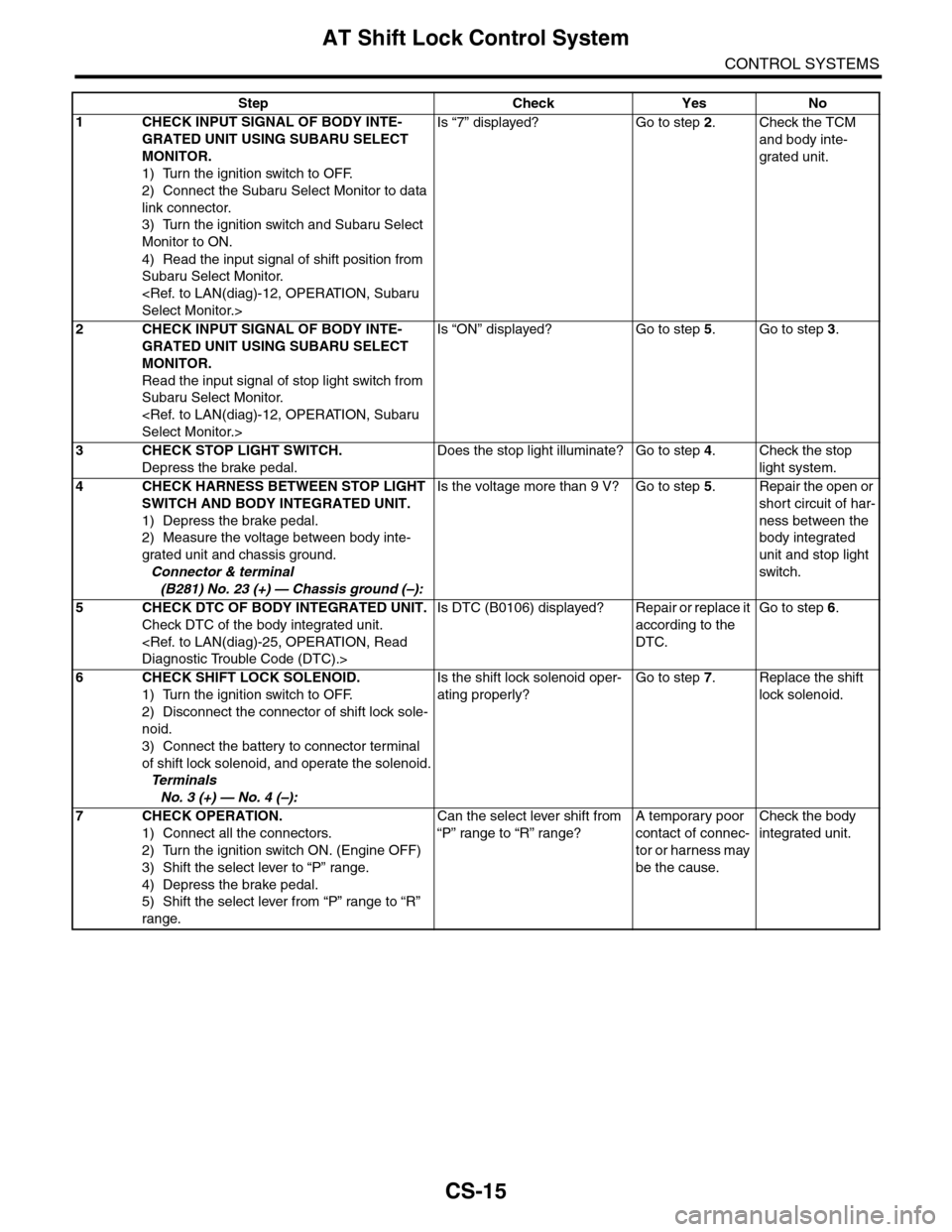
Step Check Yes No
1CHECK INPUT SIGNAL OF BODY INTE-
GRATED UNIT USING SUBARU SELECT
MONITOR.
1) Turn the ignition switch to OFF.
2) Connect the Subaru Select Monitor to data
link connector.
3) Turn the ignition switch and Subaru Select
Monitor to ON.
4) Read the input signal of shift position from
Subaru Select Monitor.
Is “7” displayed? Go to step 2.Check the TCM
and body inte-
grated unit.
2CHECK INPUT SIGNAL OF BODY INTE-
GRATED UNIT USING SUBARU SELECT
MONITOR.
Read the input signal of stop light switch from
Subaru Select Monitor.
Is “ON” displayed? Go to step 5.Go to step 3.
3CHECK STOP LIGHT SWITCH.
Depress the brake pedal.
Does the stop light illuminate? Go to step 4.Check the stop
light system.
4CHECK HARNESS BETWEEN STOP LIGHT
SWITCH AND BODY INTEGRATED UNIT.
1) Depress the brake pedal.
2) Measure the voltage between body inte-
grated unit and chassis ground.
Connector & terminal
(B281) No. 23 (+) — Chassis ground (–):
Is the voltage more than 9 V? Go to step 5.Repair the open or
short circuit of har-
ness between the
body integrated
unit and stop light
switch.
5CHECK DTC OF BODY INTEGRATED UNIT.
Check DTC of the body integrated unit.
Is DTC (B0106) displayed? Repair or replace it
according to the
DTC.
Go to step 6.
6CHECK SHIFT LOCK SOLENOID.
1) Turn the ignition switch to OFF.
2) Disconnect the connector of shift lock sole-
noid.
3) Connect the battery to connector terminal
of shift lock solenoid, and operate the solenoid.
Te r m i n a l s
No. 3 (+) — No. 4 (–):
Is the shift lock solenoid oper-
ating properly?
Go to step 7.Replace the shift
lock solenoid.
7CHECK OPERATION.
1) Connect all the connectors.
2) Turn the ignition switch ON. (Engine OFF)
3) Shift the select lever to “P” range.
4) Depress the brake pedal.
5) Shift the select lever from “P” range to “R”
range.
Can the select lever shift from
“P” range to “R” range?
A temporary poor
contact of connec-
tor or harness may
be the cause.
Check the body
integrated unit.
Page 2272 of 2453
CS-20
Select Lever
CONTROL SYSTEMS
3) Install the shift select cable onto select lever.
4) Install the center console.
5) Install the console box.
6) Shift the select lever to “N” range.
7) Lift–up the vehicle.
8) Shift the range select lever to the “N” range.
9) Secure the cable to the bracket.
10) Adjust the select cable position.
11) After the completion of adjustment, confirm that
the select lever operates properly at all range posi-
tions.
12) Install the heat shield cover.
13) Install the rear exhaust pipe and muffler.
Pipe.>
14) Inspect the following items. When a malfunc-
tion is found in the inspection, adjust the select ca-
ble.
(1) Engine starts when the select lever is in “P”
and “N” range, but not in other ranges.
(2) Back-up light illuminates when the select le-
ver is in the “R” range, but not in other ranges.
(3) Select lever and indicator positions are
matched.
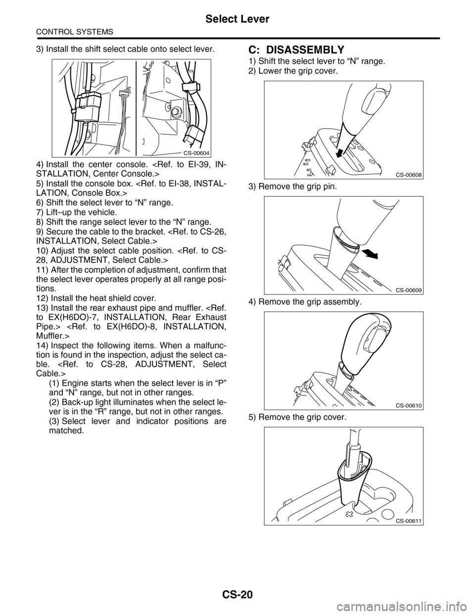
C: DISASSEMBLY
1) Shift the select lever to “N” range.
2) Lower the grip cover.
3) Remove the grip pin.
4) Remove the grip assembly.
5) Remove the grip cover.
CS-00604
CS-00608
CS-00609
CS-00610
CS-00611
Page 2279 of 2453
CS-27
Select Cable
CONTROL SYSTEMS
3) Install the plate assembly to transmission.
Tightening torque:
24.5 N·m (2.5 kgf-m, 18.1 ft-lb)
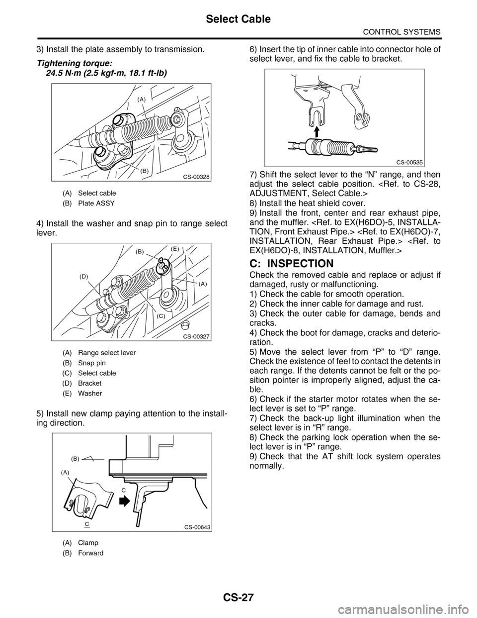
4) Install the washer and snap pin to range select
lever.
5) Install new clamp paying attention to the install-
ing direction.
6) Insert the tip of inner cable into connector hole of
select lever, and fix the cable to bracket.
7) Shift the select lever to the “N” range, and then
adjust the select cable position.
8) Install the heat shield cover.
9) Install the front, center and rear exhaust pipe,
and the muffler.
C: INSPECTION
Check the removed cable and replace or adjust if
damaged, rusty or malfunctioning.
1) Check the cable for smooth operation.
2) Check the inner cable for damage and rust.
3) Check the outer cable for damage, bends and
cracks.
4) Check the boot for damage, cracks and deterio-
ration.
5) Move the select lever from “P” to “D” range.
Check the existence of feel to contact the detents in
each range. If the detents cannot be felt or the po-
sition pointer is improperly aligned, adjust the ca-
ble.
6) Check if the starter motor rotates when the se-
lect lever is set to “P” range.
7) Check the back-up light illumination when the
select lever is in “R” range.
8) Check the parking lock operation when the se-
lect lever is in “P” range.
9) Check that the AT shift lock system operates
normally.
(A) Select cable
(B) Plate ASSY
(A) Range select lever
(B) Snap pin
(C) Select cable
(D) Bracket
(E) Washer
(A) Clamp
(B) Forward
(A)
(B)CS-00328
CS-00327
(B)
(D)
(C)
(E)
(A)
CS-00643
(A)
(B)
C
C
CS-00535
Page 2285 of 2453
CS-33
General Diagnostic Table
CONTROL SYSTEMS
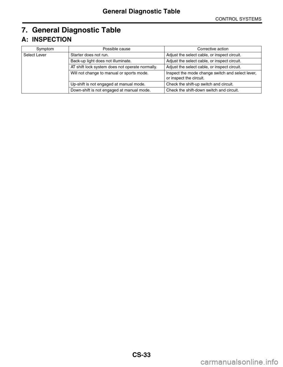
7. General Diagnostic Table
A: INSPECTION
Symptom Possible cause Corrective action
Select Lever Starter does not run. Adjust the select cable, or inspect circuit.
Back-up light does not illuminate. Adjust the select cable, or inspect circuit.
AT s h i f t l o c k s y s t e m d o e s n o t o p e r a t e n o r m a l l y. A d j u s t t h e s e l e c t c a b l e , o r i n s p e c t c i r c u i t .
Will not change to manual or sports mode. Inspect the mode change switch and select lever,
or inspect the circuit.
Up-shift is not engaged at manual mode. Check the shift-up switch and circuit.
Down-shift is not engaged at manual mode. Check the shift-down switch and circuit.
Page 2287 of 2453
WI-3
Basic Diagnostic Procedure
WIRING SYSTEM
1. Basic Diagnostic Procedure
A: BASIC PROCEDURES
1. GENERAL DESCRIPTION
The most important purpose of diagnostics is to
quickly determine which part is malfunctioning, to
save time and labor.
2. IDENTIFICATION OF TROUBLE SYMP-
TOM
Determine what the problem is based on the symp-
tom.
3. PROBABLE CAUSE OF TROUBLE
Look at the wiring diagram and check the system’s
circuit. Then check the switch, relay, fuse, ground,
etc.
4. LOCATION AND REPAIR OF TROUBLE
1) Using the diagnostics, narrow down the causes.
2) If necessary, use a voltmeter, ohmmeter, etc.
3) Before replacing certain component parts
(switch, relay, etc.), check the power supply,
ground, for open wiring harness, poor connectors,
etc. If no problem is encountered, check the com-
ponent parts.
5. SYSTEM OPERATION CHECK
After repairing, ensure that the system operates
properly.
B: BASIC INSPECTION
1. VOLTAGE MEASUREMENT
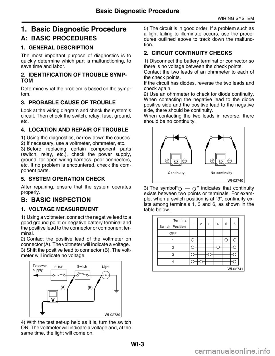
1) Using a voltmeter, connect the negative lead to a
good ground point or negative battery terminal and
the positive lead to the connector or component ter-
minal.
2) Contact the positive lead of the voltmeter on
connector (A). The voltmeter will indicate a voltage.
3) Shift the positive lead to connector (B). The volt-
meter will indicate no voltage.
4) With the test set-up held as it is, turn the switch
ON. The voltmeter will indicate a voltage and, at the
same time, the light will come on.
5) The circuit is in good order. If a problem such as
a light failing to illuminate occurs, use the proce-
dures outlined above to track down the malfunc-
tion.
2. CIRCUIT CONTINUITY CHECKS
1) Disconnect the battery terminal or connector so
there is no voltage between the check points.
Contact the two leads of an ohmmeter to each of
the check points.
If the circuit has diodes, reverse the two leads and
check again.
2) Use an ohmmeter to check for diode continuity.
When contacting the negative lead to the diode
positive side and the positive lead to the negative
side, there should be continuity.
When contacting the two leads in reverse, there
should be no continuity.
3) The symbol“ — ” indicates that continuity
exists between two points or terminals. For exam-
ple, when a switch position is at “3”, continuity ex-
ists among terminals 1, 3 and 6, as shown in the
table below.
WI-02739
To powerFUSEsupplySwitchLight
V
(A)(B)
WI-02740
Continuity No continuity
�
Page 2288 of 2453
WI-4
Basic Diagnostic Procedure
WIRING SYSTEM
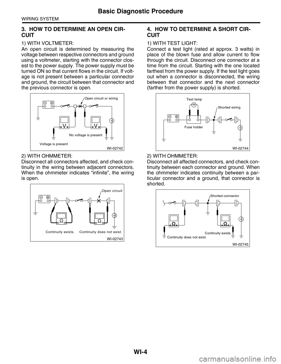
3. HOW TO DETERMINE AN OPEN CIR-
CUIT
1) WITH VOLTMETER:
An open circuit is determined by measuring the
voltage between respective connectors and ground
using a voltmeter, starting with the connector clos-
est to the power supply. The power supply must be
turned ON so that current flows in the circuit. If volt-
age is not present between a particular connector
and ground, the circuit between that connector and
the previous connector is open.
2) WITH OHMMETER:
Disconnect all connectors affected, and check con-
tinuity in the wiring between adjacent connectors.
When the ohmmeter indicates “infinite”, the wiring
is open.
4. HOW TO DETERMINE A SHORT CIR-
CUIT
1) WITH TEST LIGHT:
Connect a test light (rated at approx. 3 watts) in
place of the blown fuse and allow current to flow
through the circuit. Disconnect one connector at a
time from the circuit. Starting with the one located
farthest from the power supply. If the test light goes
out when a connector is disconnected, the wiring
between that connector and the next connector
(farther from the power supply) is shorted.
2) WITH OHMMETER:
Disconnect all affected connectors, and check con-
tinuity between each connector and ground. When
the ohmmeter indicates continuity between a par-
ticular connector and a ground, that connector is
shorted.
WI-02742
Open circuit or wiring
No voltage is present
Voltage is present
VV
WI-02743
Open circuit
Continuity does not exist.Continuity exists.
WI-02744
Shorted wiring
Test lamp
Fuse holder
WI-02745
Shorted connector
Continuity does not exist.Continuity exists.
Page 2290 of 2453
WI-6
Basic Diagnostic Procedure
WIRING SYSTEM
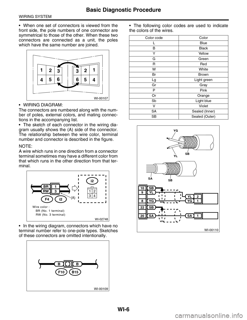
•When one set of connectors is viewed from the
front side, the pole numbers of one connector are
symmetrical to those of the other. When these two
connectors are connected as a unit, the poles
which have the same number are joined.
•WIRING DIAGRAM:
The connectors are numbered along with the num-
ber of poles, external colors, and mating connec-
tions in the accompanying list.
•The sketch of each connector in the wiring dia-
gram usually shows the (A) side of the connector.
The relationship between the wire color, terminal
number and connector is described in the figure.
NOTE:
A wire which runs in one direction from a connector
terminal sometimes may have a different color from
that which runs in the other direction from that ter-
minal.
•In the wiring diagram, connectors which have no
terminal number refer to one-pole types. Sketches
of these connectors are omitted intentionally.
•The following color codes are used to indicate
the colors of the wires.
WI-00107
112233
445566
WI-02748
Wire color :BR (No. 1 terminal)RW (No. 3 terminal)
i2
34
12
BR
RW
i2F4
1
3
(A)
WI-00109
BB
B15F10
Color code Color
LBlue
BBlack
YYellow
GGreen
RRed
WWhite
Br Brown
Lg Light green
Gr Gray
PPink
Or Orange
Sb Light blue
VViolet
SA Sealed (Inner)
SB Sealed (Outer)
WI-00110
YL 2
YG 1
SB10
YL9
YG8
SA 1
SB22
SA20
YG
YLSB
SBSA