2009 SUBARU TRIBECA light
[x] Cancel search: lightPage 1966 of 2453
SC(H6DO)-8
Starter
STARTING/CHARGING SYSTEMS
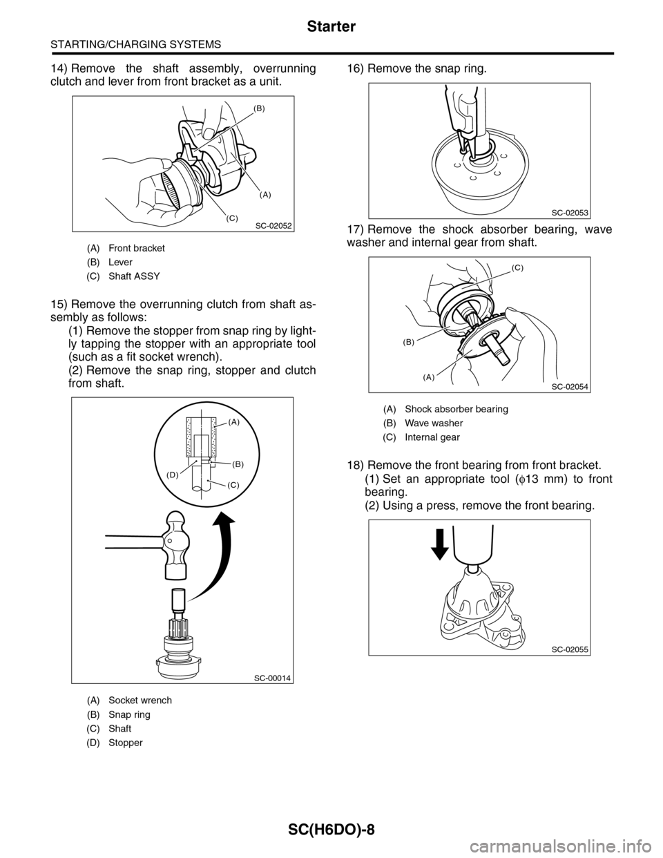
14) Remove the shaft assembly, overrunning
clutch and lever from front bracket as a unit.
15) Remove the overrunning clutch from shaft as-
sembly as follows:
(1) Remove the stopper from snap ring by light-
ly tapping the stopper with an appropriate tool
(such as a fit socket wrench).
(2) Remove the snap ring, stopper and clutch
from shaft.
16) Remove the snap ring.
17) Remove the shock absorber bearing, wave
washer and internal gear from shaft.
18) Remove the front bearing from front bracket.
(1) Set an appropriate tool (φ13 mm) to front
bearing.
(2) Using a press, remove the front bearing.
(A) Front bracket
(B) Lever
(C) Shaft ASSY
(A) Socket wrench
(B) Snap ring
(C) Shaft
(D) Stopper
SC-02052
(B)
(A)
(C)
SC-00014
(A)
(B)
(C)(D)
(A) Shock absorber bearing
(B) Wave washer
(C) Internal gear
SC-02053
SC-02054
(C)
(A)
(B)
SC-02055
Page 1968 of 2453
SC(H6DO)-10
Starter
STARTING/CHARGING SYSTEMS
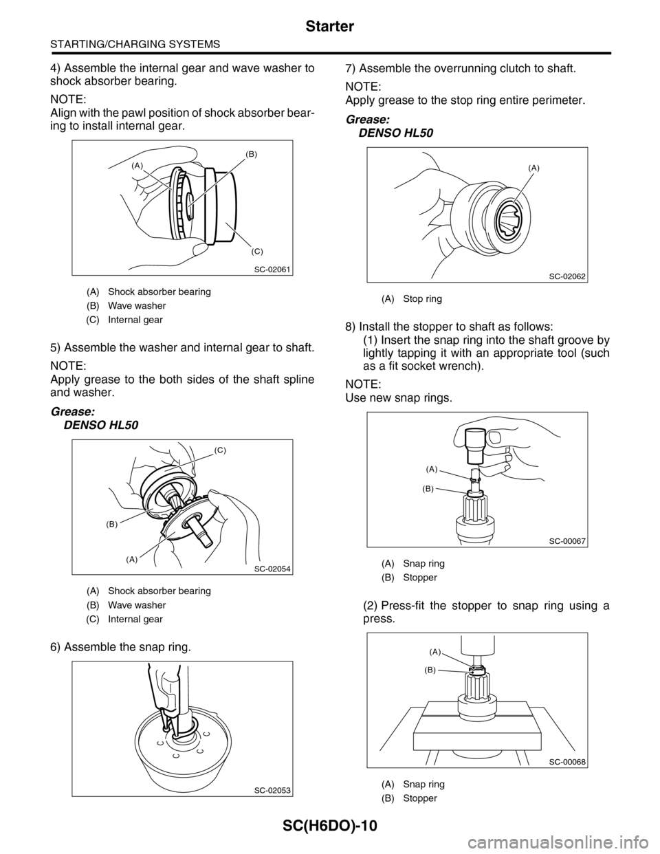
4) Assemble the internal gear and wave washer to
shock absorber bearing.
NOTE:
Align with the pawl position of shock absorber bear-
ing to install internal gear.
5) Assemble the washer and internal gear to shaft.
NOTE:
Apply grease to the both sides of the shaft spline
and washer.
Grease:
DENSO HL50
6) Assemble the snap ring.
7) Assemble the overrunning clutch to shaft.
NOTE:
Apply grease to the stop ring entire perimeter.
Grease:
DENSO HL50
8) Install the stopper to shaft as follows:
(1) Insert the snap ring into the shaft groove by
lightly tapping it with an appropriate tool (such
as a fit socket wrench).
NOTE:
Use new snap rings.
(2) Press-fit the stopper to snap ring using a
press.
(A) Shock absorber bearing
(B) Wave washer
(C) Internal gear
(A) Shock absorber bearing
(B) Wave washer
(C) Internal gear
SC-02061
(A)
(B)
(C)
SC-02054
(C)
(A)
(B)
SC-02053
(A) Stop ring
(A) Snap ring
(B) Stopper
(A) Snap ring
(B) Stopper
SC-02062
(A)
SC-00067
(B)
(A)
SC-00068
(A)
(B)
Page 1992 of 2453

PM-9
Spark Plug
PERIODIC MAINTENANCE SERVICES
5. Spark Plug
A: REPLACEMENT
1) Remove the battery and battery carrier.
2) Remove the air cleaner case.
3) Detach the connector from ignition coil.
4) Remove the ignition coil.
5) Remove the spark plug with a spark plug socket.
6) Tighten the new spark plug lightly with hand, and
then secure with a spark plug socket to the speci-
fied torque.
Recommended spark plug:
NGK: ILFR6B
Tightening torque:
21 N·m (2.1 kgf-m, 15.2 ft-lb)
7) Tighten the ignition coil.
Tightening torque:
16 N·m (1.6 kgf-m, 11.7 ft-lb)
NOTE:
•Be sure to place the gasket between the cylinder
head and spark plug.
•If the torque wrench is not available, tighten the
spark plug until gasket contacts cylinder head; then
tighten further 1/4 to 1/2 turns.
(A) Bracket
(B) Connector
IG-02004(B)
(A)
PM-00112
Page 2002 of 2453
PM-19
Brake Line
PERIODIC MAINTENANCE SERVICES
13.Brake Line
A: INSPECTION
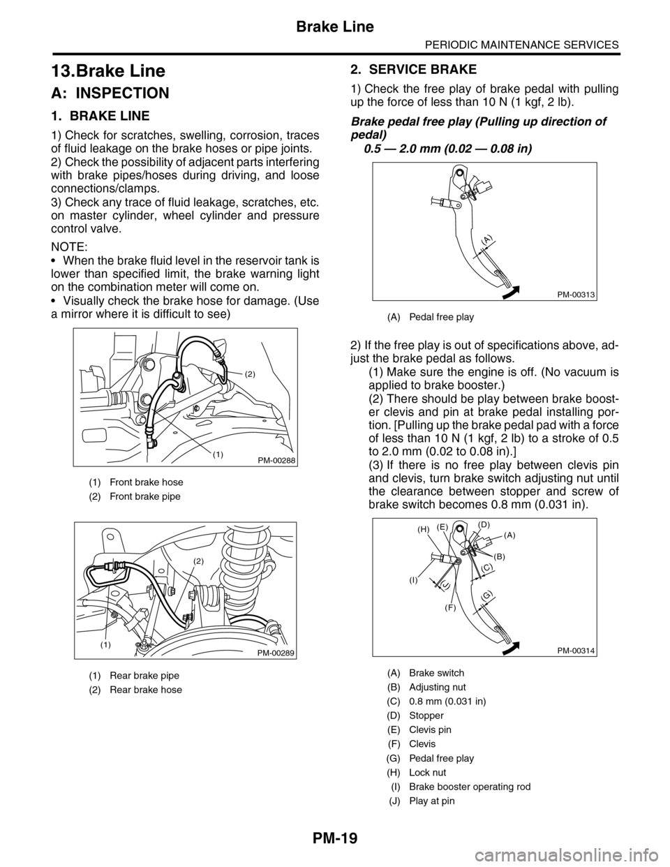
1. BRAKE LINE
1) Check for scratches, swelling, corrosion, traces
of fluid leakage on the brake hoses or pipe joints.
2) Check the possibility of adjacent parts interfering
with brake pipes/hoses during driving, and loose
connections/clamps.
3) Check any trace of fluid leakage, scratches, etc.
on master cylinder, wheel cylinder and pressure
control valve.
NOTE:
•When the brake fluid level in the reservoir tank is
lower than specified limit, the brake warning light
on the combination meter will come on.
•Visually check the brake hose for damage. (Use
a mirror where it is difficult to see)
2. SERVICE BRAKE
1) Check the free play of brake pedal with pulling
up the force of less than 10 N (1 kgf, 2 lb).
Brake pedal free play (Pulling up direction of
pedal)
0.5 — 2.0 mm (0.02 — 0.08 in)
2) If the free play is out of specifications above, ad-
just the brake pedal as follows.
(1) Make sure the engine is off. (No vacuum is
applied to brake booster.)
(2) There should be play between brake boost-
er clevis and pin at brake pedal installing por-
tion. [Pulling up the brake pedal pad with a force
of less than 10 N (1 kgf, 2 lb) to a stroke of 0.5
to 2.0 mm (0.02 to 0.08 in).]
(3) If there is no free play between clevis pin
and clevis, turn brake switch adjusting nut until
the clearance between stopper and screw of
brake switch becomes 0.8 mm (0.031 in).
(1) Front brake hose
(2) Front brake pipe
(1) Rear brake pipe
(2) Rear brake hose
PM-00288
(2)
(1)
PM-00289(1)
(2)
(A) Pedal free play
(A) Brake switch
(B) Adjusting nut
(C) 0.8 mm (0.031 in)
(D) Stopper
(E) Clevis pin
(F) Clevis
(G) Pedal free play
(H) Lock nut
(I) Brake booster operating rod
(J) Play at pin
PM-00313
(A)
PM-00314
(G)
(A)(D)(E)
(B)
(C)
(F)
(J)(I)
(H)
Page 2003 of 2453
PM-20
Brake Line
PERIODIC MAINTENANCE SERVICES
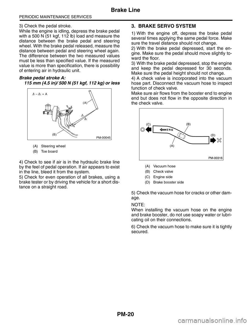
3) Check the pedal stroke.
While the engine is idling, depress the brake pedal
with a 500 N (51 kgf, 112 lb) load and measure the
distance between the brake pedal and steering
wheel. With the brake pedal released, measure the
distance between pedal and steering wheel again.
The difference between the two measured values
must be less than specified value. If the measured
value is more than specification, there is possibility
of entering air in hydraulic unit.
Brake pedal stroke A:
115 mm (4.5 in)/ 500 N (51 kgf, 112 kg) or less
4) Check to see if air is in the hydraulic brake line
by the feel of pedal operation. If air appears to exist
in the line, bleed it from the system.
5) Check for even operation of all brakes, using a
brake tester or by driving the vehicle for a short dis-
tance on a straight road.
3. BRAKE SERVO SYSTEM
1) With the engine off, depress the brake pedal
several times applying the same pedal force. Make
sure the travel distance should not change.
2) With the brake pedal depressed, start the en-
gine. Make sure the pedal should move slightly to-
ward the floor.
3) With the brake pedal depressed, stop the engine
and keep the pedal depressed for 30 seconds.
Make sure the pedal height should not change.
4) A check valve is incorporated into the vacuum
hose part. Disconnect the vacuum hose to inspect
function of check valve.
Make sure air flows from the booster end to engine
end but does not flow in the opposite direction in
the check valve.
5) Check the vacuum hose for cracks or other dam-
age.
NOTE:
When installing the vacuum hose on the engine
and brake booster, do not use soapy water or lubri-
cating oil on their connections.
6) Check the vacuum hose to make sure it is tightly
secured.
(A) Steering wheel
(B) Toe board
PM-00045(B)
(A)
= A
1
12
2
(A) Vacuum hose
(B) Check valve
(C) Engine side
(D) Brake booster side
Page 2006 of 2453
PM-23
Parking Brake
PERIODIC MAINTENANCE SERVICES
16.Parking Brake
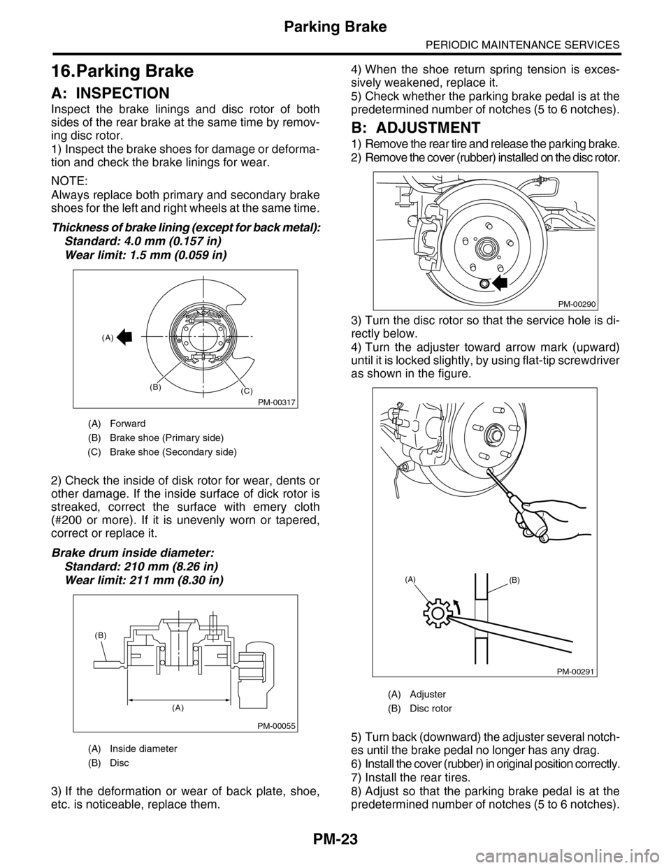
A: INSPECTION
Inspect the brake linings and disc rotor of both
sides of the rear brake at the same time by remov-
ing disc rotor.
1) Inspect the brake shoes for damage or deforma-
tion and check the brake linings for wear.
NOTE:
Always replace both primary and secondary brake
shoes for the left and right wheels at the same time.
Thickness of brake lining (except for back metal):
Standard: 4.0 mm (0.157 in)
Wear limit: 1.5 mm (0.059 in)
2) Check the inside of disk rotor for wear, dents or
other damage. If the inside surface of dick rotor is
streaked, correct the surface with emery cloth
(#200 or more). If it is unevenly worn or tapered,
correct or replace it.
Brake drum inside diameter:
Standard: 210 mm (8.26 in)
Wear limit: 211 mm (8.30 in)
3) If the deformation or wear of back plate, shoe,
etc. is noticeable, replace them.
4) When the shoe return spring tension is exces-
sively weakened, replace it.
5) Check whether the parking brake pedal is at the
predetermined number of notches (5 to 6 notches).
B: ADJUSTMENT
1) Remove the rear tire and release the parking brake.
2) Remove the cover (rubber) installed on the disc rotor.
3) Turn the disc rotor so that the service hole is di-
rectly below.
4) Turn the adjuster toward arrow mark (upward)
until it is locked slightly, by using flat-tip screwdriver
as shown in the figure.
5) Turn back (downward) the adjuster several notch-
es until the brake pedal no longer has any drag.
6) Install the cover (rubber) in original position correctly.
7) Install the rear tires.
8) Adjust so that the parking brake pedal is at the
predetermined number of notches (5 to 6 notches).
(A) Forward
(B) Brake shoe (Primary side)
(C) Brake shoe (Secondary side)
(A) Inside diameter
(B) Disc
PM-00317
(A)
(B)(C)
PM-00055
(A)
(B)
(A) Adjuster
(B) Disc rotor
PM-00290
PM-00291
(A)(B)
Page 2012 of 2453
PM-29
Steering System (Power Steering)
PERIODIC MAINTENANCE SERVICES
21.Steering System (Power
Steering)
A: INSPECTION
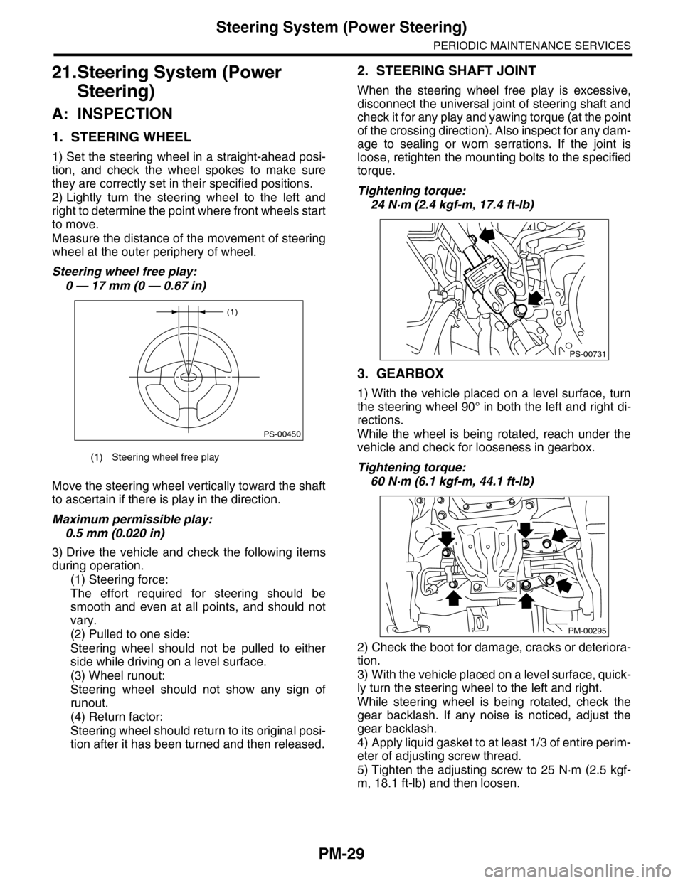
1. STEERING WHEEL
1) Set the steering wheel in a straight-ahead posi-
tion, and check the wheel spokes to make sure
they are correctly set in their specified positions.
2) Lightly turn the steering wheel to the left and
right to determine the point where front wheels start
to move.
Measure the distance of the movement of steering
wheel at the outer periphery of wheel.
Steering wheel free play:
0 — 17 mm (0 — 0.67 in)
Move the steering wheel vertically toward the shaft
to ascertain if there is play in the direction.
Maximum permissible play:
0.5 mm (0.020 in)
3) Drive the vehicle and check the following items
during operation.
(1) Steering force:
The effort required for steering should be
smooth and even at all points, and should not
vary.
(2) Pulled to one side:
Steering wheel should not be pulled to either
side while driving on a level surface.
(3) Wheel runout:
Steering wheel should not show any sign of
runout.
(4) Return factor:
Steering wheel should return to its original posi-
tion after it has been turned and then released.
2. STEERING SHAFT JOINT
When the steering wheel free play is excessive,
disconnect the universal joint of steering shaft and
check it for any play and yawing torque (at the point
of the crossing direction). Also inspect for any dam-
age to sealing or worn serrations. If the joint is
loose, retighten the mounting bolts to the specified
torque.
Tightening torque:
24 N·m (2.4 kgf-m, 17.4 ft-lb)
3. GEARBOX
1) With the vehicle placed on a level surface, turn
the steering wheel 90° in both the left and right di-
rections.
While the wheel is being rotated, reach under the
vehicle and check for looseness in gearbox.
Tightening torque:
60 N·m (6.1 kgf-m, 44.1 ft-lb)
2) Check the boot for damage, cracks or deteriora-
tion.
3) With the vehicle placed on a level surface, quick-
ly turn the steering wheel to the left and right.
While steering wheel is being rotated, check the
gear backlash. If any noise is noticed, adjust the
gear backlash.
4) Apply liquid gasket to at least 1/3 of entire perim-
eter of adjusting screw thread.
5) Tighten the adjusting screw to 25 N·m (2.5 kgf-
m, 18.1 ft-lb) and then loosen.
(1) Steering wheel free play
(1)
PS-00450
PS-00731
PM-00295
Page 2015 of 2453
PM-32
Supplemental Restraint System
PERIODIC MAINTENANCE SERVICES
22.Supplemental Restraint System
A: INSPECTION
Check the airbag system in accordance with the result of the self-diagnosis.
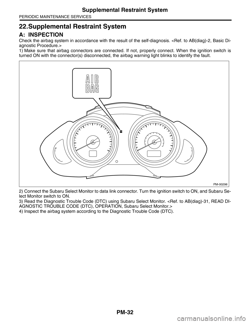
1) Make sure that airbag connectors are connected. If not, properly connect. When the ignition switch is
turned ON with the connector(s) disconnected, the airbag warning light blinks to identify the fault.
2) Connect the Subaru Select Monitor to data link connector. Turn the ignition switch to ON, and Subaru Se-
lect Monitor switch to ON.
3) Read the Diagnostic Trouble Code (DTC) using Subaru Select Monitor.
4) Inspect the airbag system according to the Diagnostic Trouble Code (DTC).
PM-00298