Page 1726 of 2453
GD(H6DO)-114
Diagnostic Trouble Code (DTC) Detecting Criteria
GENERAL DESCRIPTION
BX:DTC P0335 CRANKSHAFT POSITION SENSOR “A” CIRCUIT
1. OUTLINE OF DIAGNOSIS
Detect the open or short circuit of the crankshaft position sensor.
Judge as NG when the crank signal is not input even though the starter was rotated.
2. COMPONENT DESCRIPTION
3. ENABLE CONDITIONS
(A) Camshaft signal (RH) (B) Camshaft signal (LH) (C) Crankshaft signal
(1) Crankshaft position sensor (2) Crank sprocket (3) Crankshaft half-turn
Secondary Parameters Enable Conditions
None
(A)
(C)#6BTDC10 CA#3BTDC10 CA#2BTDC10 CA#5BTDC10 CA#4BTDC10 CA
10 CA30 CA30 CA
#1BTDC10 CA#1BTDC10 CA
EN-03092
(B)
2 ENGINE ROTATION AND 3 CAMSHAFT POSITION SENSOR SIGNALS BETWEEN 0 CA - 0 CA IS NORMAL
EN-02188
( 1 )
( 2 )
( 3 )
Page 1728 of 2453
GD(H6DO)-116
Diagnostic Trouble Code (DTC) Detecting Criteria
GENERAL DESCRIPTION
BY:DTC P0336 CRANKSHAFT POSITION SENSOR “A” CIRCUIT RANGE/PER-
FORMANCE
1. OUTLINE OF DIAGNOSIS
Detect for faults in crankshaft position sensor output properties.
Judge as NG when there is a problem in the number of crankshaft signals for every revolution.
2. COMPONENT DESCRIPTION
(A) Camshaft signal (RH) (B) Camshaft signal (LH) (C) Crankshaft signal
(1) Crankshaft position sensor (2) Crank sprocket (3) Crankshaft half-turn
(A)
(C)#6BTDC10 CA#3BTDC10 CA#2BTDC10 CA#5BTDC10 CA#4BTDC10 CA
10 CA30 CA30 CA
#1BTDC10 CA#1BTDC10 CA
EN-03092
(B)
2 ENGINE ROTATION AND 3 CAMSHAFT POSITION SENSOR SIGNALS BETWEEN 0 CA - 0 CA IS NORMAL
EN-02188
( 1 )
( 2 )
( 3 )
Page 1730 of 2453
GD(H6DO)-118
Diagnostic Trouble Code (DTC) Detecting Criteria
GENERAL DESCRIPTION
BZ:DTC P0340 CAMSHAFT POSITION SENSOR “A” CIRCUIT (BANK 1 OR SIN-
GLE SENSOR)
1. OUTLINE OF DIAGNOSIS
Detect the open or short circuit of the camshaft position sensor.
Judge as NG when the number of camshaft signals remains abnormal.
2. COMPONENT DESCRIPTION
(A) Camshaft signal (RH) (B) Camshaft signal (LH) (C) Crankshaft signal
(1) Throttle (3) Detecting point (4) Camshaft one revolution (engine
two revolutions)(2) Camshaft plate
(A)
(C)#6BTDC10 CA#3BTDC10 CA#2BTDC10 CA#5BTDC10 CA#4BTDC10 CA
10 CA30 CA30 CA
#1BTDC10 CA#1BTDC10 CA
EN-03092
(B)
2 ENGINE ROTATION AND 3 CAMSHAFT POSITION SENSOR SIGNALS BETWEEN 0 CA - 0 CA IS NORMAL
EN-02190
( 1 )
( 2 )
( 3 )
( 4 )
Page 1731 of 2453

GD(H6DO)-119
Diagnostic Trouble Code (DTC) Detecting Criteria
GENERAL DESCRIPTION
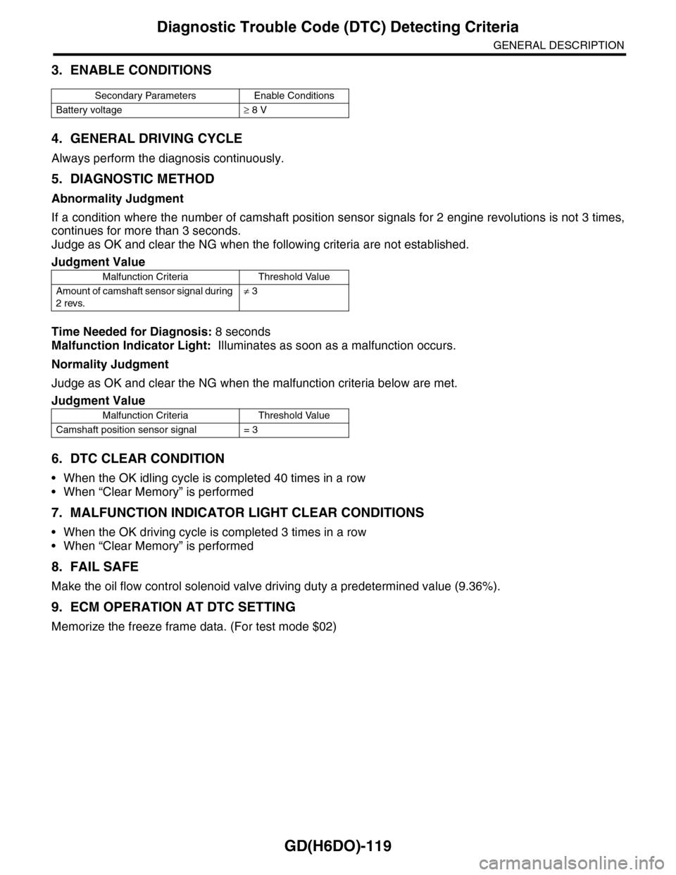
3. ENABLE CONDITIONS
4. GENERAL DRIVING CYCLE
Always perform the diagnosis continuously.
5. DIAGNOSTIC METHOD
Abnormality Judgment
If a condition where the number of camshaft position sensor signals for 2 engine revolutions is not 3 times,
continues for more than 3 seconds.
Judge as OK and clear the NG when the following criteria are not established.
Time Needed for Diagnosis: 8 seconds
Malfunction Indicator Light: Illuminates as soon as a malfunction occurs.
Normality Judgment
Judge as OK and clear the NG when the malfunction criteria below are met.
6. DTC CLEAR CONDITION
•When the OK idling cycle is completed 40 times in a row
•When “Clear Memory” is performed
7. MALFUNCTION INDICATOR LIGHT CLEAR CONDITIONS
•When the OK driving cycle is completed 3 times in a row
•When “Clear Memory” is performed
8. FAIL SAFE
Make the oil flow control solenoid valve driving duty a predetermined value (9.36%).
9. ECM OPERATION AT DTC SETTING
Memorize the freeze frame data. (For test mode $02)
Secondary Parameters Enable Conditions
Battery voltage≥ 8 V
Judgment Value
Malfunction Criteria Threshold Value
Amount of camshaft sensor signal during
2 revs.
≠ 3
Judgment Value
Malfunction Criteria Threshold Value
Camshaft position sensor signal = 3
Page 1732 of 2453
GD(H6DO)-120
Diagnostic Trouble Code (DTC) Detecting Criteria
GENERAL DESCRIPTION
CA:DTC P0345 CAMSHAFT POSITION SENSOR “A” CIRCUIT (BANK 2)
1. OUTLINE OF DIAGNOSIS
NOTE:
For the diagnostic procedure, refer to DTC P0340.
SITION SENSOR “A” CIRCUIT (BANK 1 OR SINGLE SENSOR), Diagnostic Trouble Code (DTC) Detecting
Criteria.>
Page 1906 of 2453

ME(H6DO)-40
Preparation for Overhaul
MECHANICAL
12.Preparation for Overhaul
A: REMOVAL
1) Remove the engine assembly from the body.
sembly.>
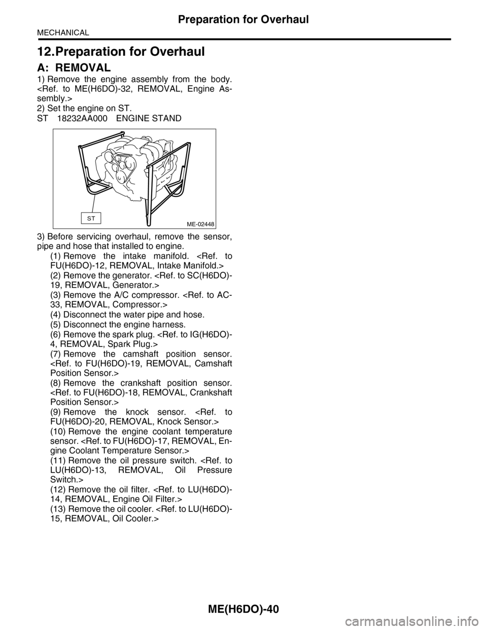
2) Set the engine on ST.
ST 18232AA000 ENGINE STAND
3) Before servicing overhaul, remove the sensor,
pipe and hose that installed to engine.
(1) Remove the intake manifold.
FU(H6DO)-12, REMOVAL, Intake Manifold.>
(2) Remove the generator.
19, REMOVAL, Generator.>
(3) Remove the A/C compressor.
33, REMOVAL, Compressor.>
(4) Disconnect the water pipe and hose.
(5) Disconnect the engine harness.
(6) Remove the spark plug.
4, REMOVAL, Spark Plug.>
(7) Remove the camshaft position sensor.
Position Sensor.>
(8) Remove the crankshaft position sensor.
Position Sensor.>
(9) Remove the knock sensor.
FU(H6DO)-20, REMOVAL, Knock Sensor.>
(10) Remove the engine coolant temperature
sensor.
gine Coolant Temperature Sensor.>
(11) Remove the oil pressure switch.
LU(H6DO)-13, REMOVAL, Oil Pressure
Switch.>
(12) Remove the oil filter.
14, REMOVAL, Engine Oil Filter.>
(13) Remove the oil cooler.
15, REMOVAL, Oil Cooler.>
STME-02448
Page 1928 of 2453

ME(H6DO)-62
Cylinder Block
MECHANICAL
21.Cylinder Block
A: REMOVAL
NOTE:
Before conducting this procedure, drain the engine
oil completely.
1) Remove the crank pulley.
41, REMOVAL, Crank Pulley.>
2) Remove the front chain cover.
ME(H6DO)-42, REMOVAL, Front Chain Cover.>
3) Remove the timing chain assembly.
Assembly.>
4) Remove the cam sprocket.
et.>
5) Remove the crank sprocket.
et.>
6) Remove the rear chain cover.
Cover.>
7) Remove the camshaft.
REMOVAL, Camshaft.>
8) Remove the cylinder head.
57, REMOVAL, Cylinder Head.>
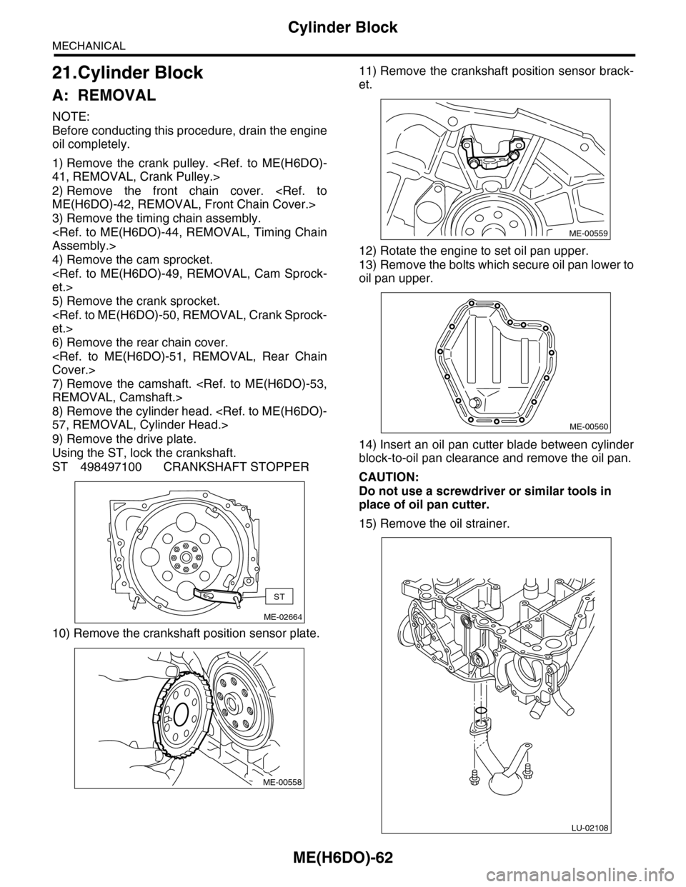
9) Remove the drive plate.
Using the ST, lock the crankshaft.
ST 498497100 CRANKSHAFT STOPPER
10) Remove the crankshaft position sensor plate.
11) Remove the crankshaft position sensor brack-
et.
12) Rotate the engine to set oil pan upper.
13) Remove the bolts which secure oil pan lower to
oil pan upper.
14) Insert an oil pan cutter blade between cylinder
block-to-oil pan clearance and remove the oil pan.
CAUTION:
Do not use a screwdriver or similar tools in
place of oil pan cutter.
15) Remove the oil strainer.
ME-02664
ST
ME-00558
ME-00559
ME-00560
LU-02108
Page 1934 of 2453
ME(H6DO)-68
Cylinder Block
MECHANICAL
26) Install the crankshaft sensor plate.
27) Install the drive plate.
To lock the crankshaft, use ST.
ST 498497100 CRANKSHAFT STOPPER
Tightening torque:
81 N·m (8.3 kgf-m, 60 ft-lb)
28) Install the cylinder head.
57, INSTALLATION, Cylinder Head.>
29) Install the camshaft.
INSTALLATION, Camshaft.>
30) Install the rear chain cover.
ME(H6DO)-51, INSTALLATION, Rear Chain Cov-
er.>
31) Install the crank sprocket.
Sprocket.>
32) Install the cam sprocket.
49, INSTALLATION, Cam Sprocket.>
33) Install the timing chain assembly.
Chain Assembly.>
34) Install the front chain cover.
Chain Cover.>
35) Install the crank pulley.
Pulley.>
ME-00558
ME-02664
ST