2009 SUBARU TRIBECA cam sensor
[x] Cancel search: cam sensorPage 1426 of 2453
EN(H6DO)(diag)-265
Diagnostic Procedure with Diagnostic Trouble Code (DTC)
ENGINE (DIAGNOSTICS)
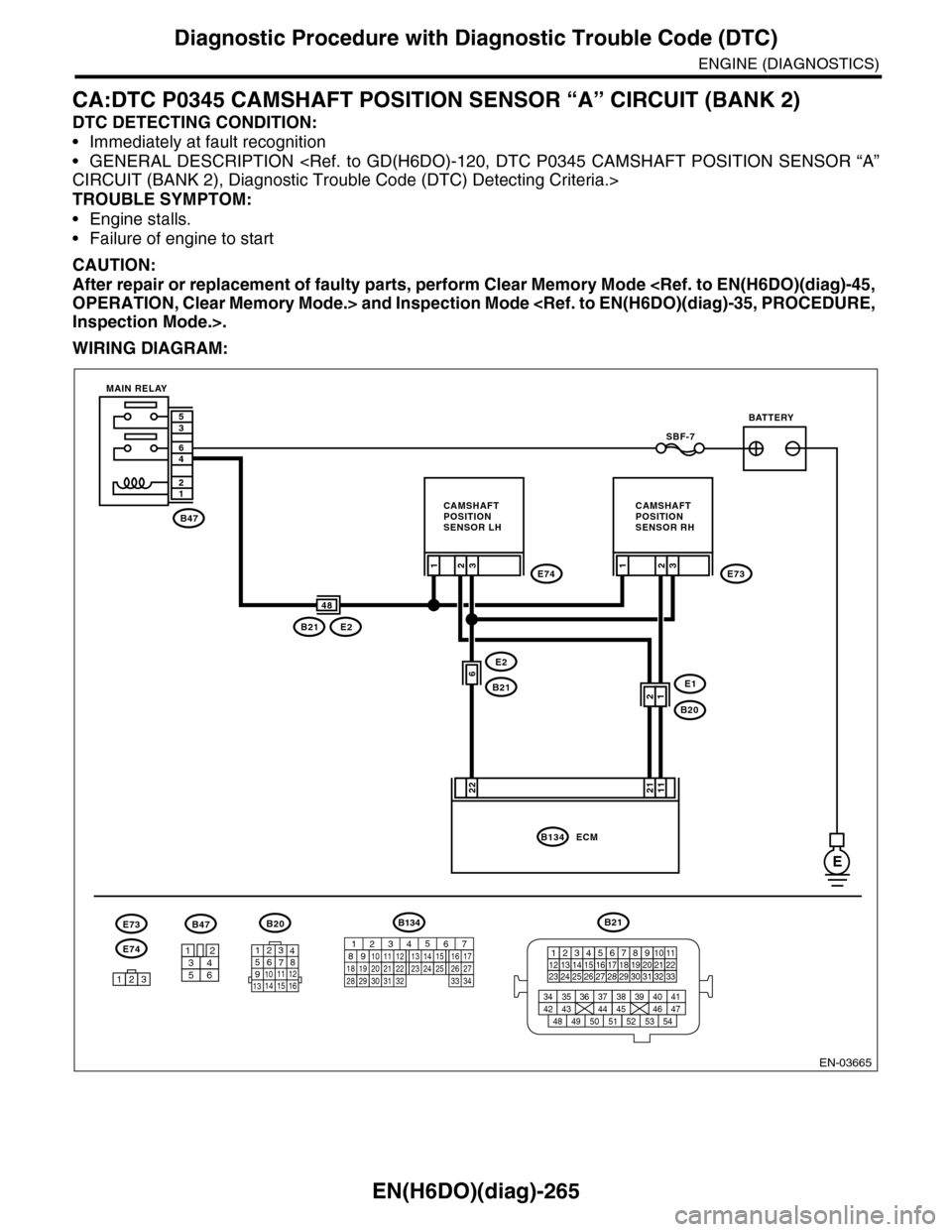
CA:DTC P0345 CAMSHAFT POSITION SENSOR “A” CIRCUIT (BANK 2)
DTC DETECTING CONDITION:
•Immediately at fault recognition
•GENERAL DESCRIPTION
TROUBLE SYMPTOM:
•Engine stalls.
•Failure of engine to start
CAUTION:
After repair or replacement of faulty parts, perform Clear Memory Mode
WIRING DIAGRAM:
EN-03665
B47
12
46
35
E
E2
B21
3
22
SBF-7
E74
E1
B20
2E73
B21E2
1
6
3
11
21
ECMB134
48
1
3412
56
B20
E74
B47
123
E73
BATTERY
CAMSHAFTPOSITIONSENSOR RH
CAMSHAFTPOSITIONSENSOR LH
MAIN RELAY
2
21
B21
123412131415567816171819910 1120212223 24 25 2627 28 29 3031 32 33
3534 37363938 41404342 4445 47464948 51505352 54
1234567891011 121314 15 16
B134
85610 11 12 13 14 157213416
3019 20 2228 29
91718252123 24323126 2733 34
Page 1427 of 2453
EN(H6DO)(diag)-266
Diagnostic Procedure with Diagnostic Trouble Code (DTC)
ENGINE (DIAGNOSTICS)
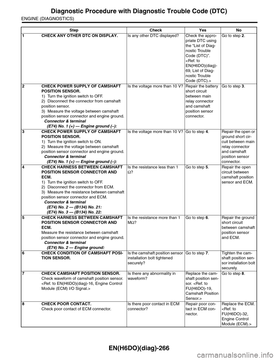
Step Check Yes No
1CHECK ANY OTHER DTC ON DISPLAY.Is any other DTC displayed? Check the appro-
priate DTC using
the “List of Diag-
nostic Trouble
Code (DTC)”.
69, List of Diag-
nostic Trouble
Code (DTC).>
Go to step 2.
2CHECK POWER SUPPLY OF CAMSHAFT
POSITION SENSOR.
1) Turn the ignition switch to OFF.
2) Disconnect the connector from camshaft
position sensor.
3) Measure the voltage between camshaft
position sensor connector and engine ground.
Connector & terminal
(E74) No. 1 (+) — Engine ground (–):
Is the voltage more than 10 V? Repair the battery
short circuit
between main
relay connector
and camshaft
position sensor
connector.
Go to step 3.
3CHECK POWER SUPPLY OF CAMSHAFT
POSITION SENSOR.
1) Turn the ignition switch to ON.
2) Measure the voltage between camshaft
position sensor connector and engine ground.
Connector & terminal
(E74) No. 1 (+) — Engine ground (–):
Is the voltage more than 10 V? Go to step 4.Repair the open or
ground short cir-
cuit between main
relay connector
and camshaft
position sensor
connector.
4CHECK HARNESS BETWEEN CAMSHAFT
POSITION SENSOR CONNECTOR AND
ECM.
1) Turn the ignition switch to OFF.
2) Disconnect the connector from ECM.
3) Measure the resistance between camshaft
position sensor connector and ECM.
Connector & terminal
(E74) No. 2 — (B134) No. 21:
(E74) No. 3 — (B134) No. 22:
Is the resistance less than 1
Ω?
Go to step 5.Repair the open
circuit between
camshaft position
sensor and ECM.
5CHECK HARNESS BETWEEN CAMSHAFT
POSITION SENSOR CONNECTOR AND
ECM.
Measure the resistance between camshaft
position sensor connector and engine ground.
Connector & terminal
(E74) No. 2 — Engine ground:
Is the resistance more than 1
MΩ?
Go to step 6.Repair the ground
short circuit
between camshaft
position sensor
and ECM.
6CHECK CONDITION OF CAMSHAFT POSI-
TION SENSOR.
Is the camshaft position sensor
installation bolt tightened
securely?
Go to step 7.Tighten the cam-
shaft position sen-
sor installation bolt
securely.
7CHECK CAMSHAFT POSITION SENSOR.
Check waveform of camshaft position sensor.
Is there any abnormality in
waveform?
Replace the cam-
shaft position sen-
sor.
Camshaft Position
Sensor.>
Go to step 8.
8CHECK POOR CONTACT.
Check poor contact of ECM connector.
Is there poor contact in ECM
connector?
Repair poor con-
tact in ECM con-
nector.
Replace the ECM.
Engine Control
Module (ECM).>
Page 1553 of 2453
EN(H6DO)(diag)-392
General Diagnostic Table
ENGINE (DIAGNOSTICS)
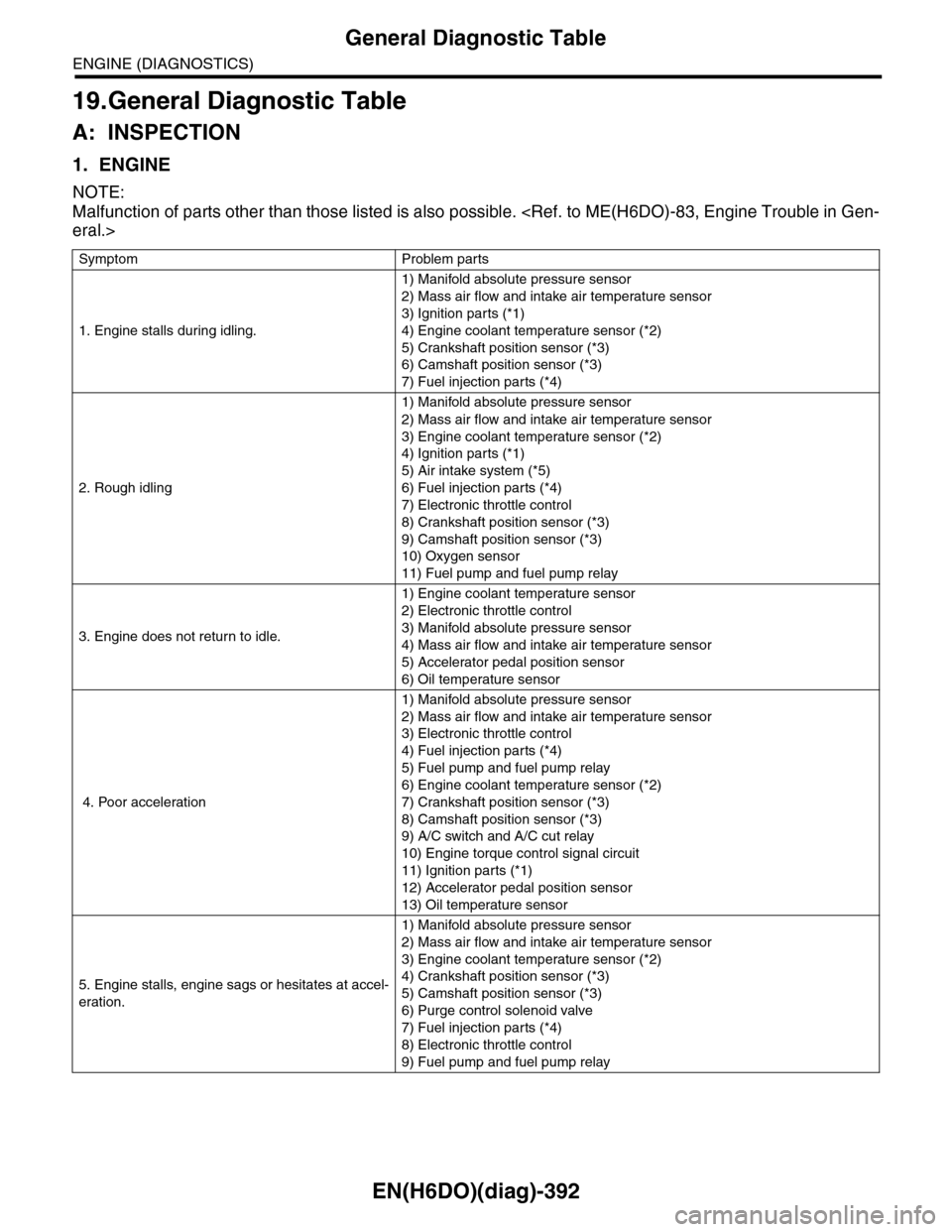
19.General Diagnostic Table
A: INSPECTION
1. ENGINE
NOTE:
Malfunction of parts other than those listed is also possible.
Symptom Problem parts
1. Engine stalls during idling.
1) Manifold absolute pressure sensor
2) Mass air flow and intake air temperature sensor
3) Ignition parts (*1)
4) Engine coolant temperature sensor (*2)
5) Crankshaft position sensor (*3)
6) Camshaft position sensor (*3)
7) Fuel injection parts (*4)
2. Rough idling
1) Manifold absolute pressure sensor
2) Mass air flow and intake air temperature sensor
3) Engine coolant temperature sensor (*2)
4) Ignition parts (*1)
5) Air intake system (*5)
6) Fuel injection parts (*4)
7) Electronic throttle control
8) Crankshaft position sensor (*3)
9) Camshaft position sensor (*3)
10) Oxygen sensor
11) Fuel pump and fuel pump relay
3. Engine does not return to idle.
1) Engine coolant temperature sensor
2) Electronic throttle control
3) Manifold absolute pressure sensor
4) Mass air flow and intake air temperature sensor
5) Accelerator pedal position sensor
6) Oil temperature sensor
4. Poor acceleration
1) Manifold absolute pressure sensor
2) Mass air flow and intake air temperature sensor
3) Electronic throttle control
4) Fuel injection parts (*4)
5) Fuel pump and fuel pump relay
6) Engine coolant temperature sensor (*2)
7) Crankshaft position sensor (*3)
8) Camshaft position sensor (*3)
9) A/C switch and A/C cut relay
10) Engine torque control signal circuit
11) Ignition parts (*1)
12) Accelerator pedal position sensor
13) Oil temperature sensor
5. Engine stalls, engine sags or hesitates at accel-
eration.
1) Manifold absolute pressure sensor
2) Mass air flow and intake air temperature sensor
3) Engine coolant temperature sensor (*2)
4) Crankshaft position sensor (*3)
5) Camshaft position sensor (*3)
6) Purge control solenoid valve
7) Fuel injection parts (*4)
8) Electronic throttle control
9) Fuel pump and fuel pump relay
Page 1554 of 2453
EN(H6DO)(diag)-393
General Diagnostic Table
ENGINE (DIAGNOSTICS)
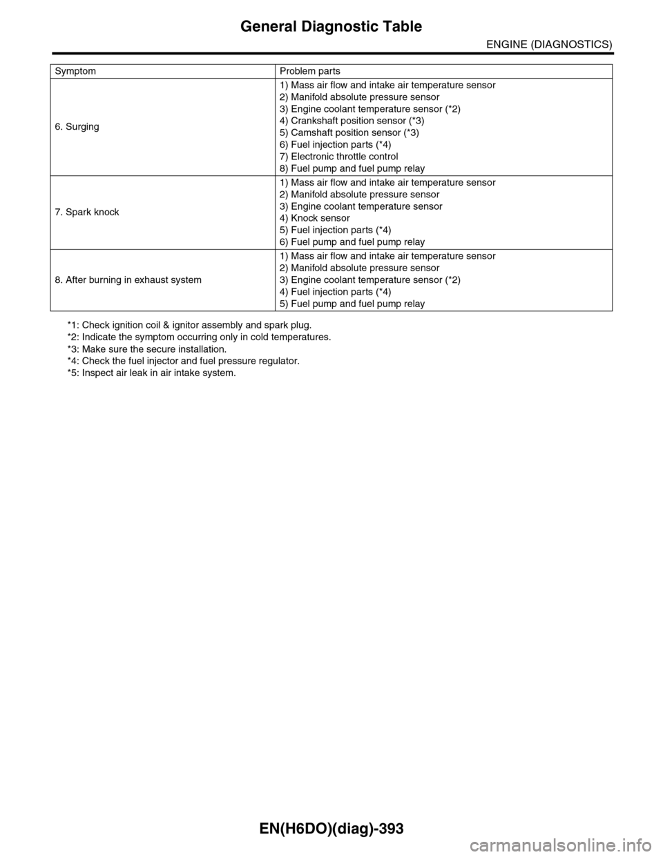
*1: Check ignition coil & ignitor assembly and spark plug.
*2: Indicate the symptom occurring only in cold temperatures.
*3: Make sure the secure installation.
*4: Check the fuel injector and fuel pressure regulator.
*5: Inspect air leak in air intake system.
6. Surging
1) Mass air flow and intake air temperature sensor
2) Manifold absolute pressure sensor
3) Engine coolant temperature sensor (*2)
4) Crankshaft position sensor (*3)
5) Camshaft position sensor (*3)
6) Fuel injection parts (*4)
7) Electronic throttle control
8) Fuel pump and fuel pump relay
7. Spark knock
1) Mass air flow and intake air temperature sensor
2) Manifold absolute pressure sensor
3) Engine coolant temperature sensor
4) Knock sensor
5) Fuel injection parts (*4)
6) Fuel pump and fuel pump relay
8. After burning in exhaust system
1) Mass air flow and intake air temperature sensor
2) Manifold absolute pressure sensor
3) Engine coolant temperature sensor (*2)
4) Fuel injection parts (*4)
5) Fuel pump and fuel pump relay
Symptom Problem parts
Page 1567 of 2453

FU(H6DO)-6
General Description
FUEL INJECTION (FUEL SYSTEMS)
4. CRANKSHAFT POSITION, CAMSHAFT POSITION AND KNOCK SENSORS
(1) Crankshaft position sensor (6) Variable valve lift diagnosis oil
pressure switch RH
Tightening torque: N·m (kgf-m, ft-lb)
(2) Knock sensor RHT1: 6.4 (0.65, 4.7)
(3) Knock sensor LH (7) Variable valve lift diagnosis oil
pressure switch LH
T2: 17 (1.7, 12.5)
(4) Camshaft position sensor RHT3: 18 (1.8, 13.3)
(5) Camshaft position sensor LH (8) Oil temperature sensorT4: 25 (2.5, 18)
FU-02110
(6)
(4)
T2
T1
(3)
T4
(1)
(8)
T1
T3
(5)
T1
(2)
T4
(7)
T2
Page 1580 of 2453
FU(H6DO)-19
Camshaft Position Sensor
FUEL INJECTION (FUEL SYSTEMS)
6. Camshaft Position Sensor
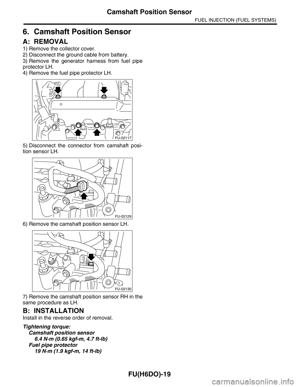
A: REMOVAL
1) Remove the collector cover.
2) Disconnect the ground cable from battery.
3) Remove the generator harness from fuel pipe
protector LH.
4) Remove the fuel pipe protector LH.
5) Disconnect the connector from camshaft posi-
tion sensor LH.
6) Remove the camshaft position sensor LH.
7) Remove the camshaft position sensor RH in the
same procedure as LH.
B: INSTALLATION
Install in the reverse order of removal.
Tightening torque:
Camshaft position sensor
6.4 N·m (0.65 kgf-m, 4.7 ft-lb)
Fuel pipe protector
19 N·m (1.9 kgf-m, 14 ft-lb)
FU-02117
FU-02129
FU-02130
Page 1614 of 2453
GD(H6DO)-2
List of Diagnostic Trouble Code (DTC)
GENERAL DESCRIPTION
1. List of Diagnostic Trouble Code (DTC)
A: LIST
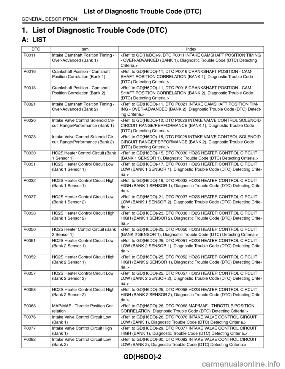
DTC Item Index
P0011 Intake Camshaft Position Timing -
Over-Advanced (Bank 1)
Criteria.>
P0016 Crankshaft Position - Camshaft
Pos it i o n C o r r el a ti o n ( B a nk 1)
(DTC) Detecting Criteria.>
P0018 Crankshaft Position - Camshaft
Pos it i o n C o r r el a ti o n ( B a nk 2)
(DTC) Detecting Criteria.>
P0021 Intake Camshaft Position Timing -
Over-Advanced (Bank 2)
ing Criteria.>
P0026 Intake Valve Control Solenoid Cir-
cuit Range/Performance (Bank 1)
(DTC) Detecting Criteria.>
P0028 Intake Valve Control Solenoid Cir-
cuit Range/Performance (Bank 2)
(DTC) Detecting Criteria.>
P0030 HO2S Heater Control Circuit (Bank
1 Sensor 1)
P0031 HO2S Heater Control Circuit Low
(Bank 1 Sensor 1)
ria.>
P0032 HO2S Heater Control Circuit High
(Bank 1 Sensor 1)
ria.>
P0037 HO2S Heater Control Circuit Low
(Bank 1 Sensor 2)
ria.>
P0038 HO2S Heater Control Circuit High
(Bank 1 Sensor 2)
ria.>
P0050 HO2S Heater Control Circuit (Bank
2 Sensor 1)
P0051 HO2S Heater Control Circuit Low
(Bank 2 Sensor 1)
ria.>
P0052 HO2S Heater Control Circuit High
(Bank 2 Sensor 1)
ria.>
P0057 HO2S Heater Control Circuit Low
(Bank 2 Sensor 2)
ria.>
P0058 HO2S Heater Control Circuit High
(Bank 2 Sensor 2)
ria.>
P0068 MAP/MAF - Throttle Position Cor-
relation
P0076 Intake Valve Control Circuit Low
(Bank 1)
P0077 Intake Valve Control Circuit High
(Bank 1)
P0082 Intake Valve Control Circuit Low
(Bank 2)
Page 1617 of 2453
GD(H6DO)-5
List of Diagnostic Trouble Code (DTC)
GENERAL DESCRIPTION
P0301 Cylinder 1 Misfire Detected
P0302 Cylinder 2 Misfire Detected
P0303 Cylinder 3 Misfire Detected
P0304 Cylinder 4 Misfire Detected
P0305 Cylinder 5 Misfire Detected
P0306 Cylinder 6 Misfire Detected
P0327 Knock Sensor 1 Circuit Low Input
(Bank 1 or Single Sensor)
Detecting Criteria.>
P0328 Knock Sensor 1 Circuit High Input
(Bank 1 or Single Sensor)
Detecting Criteria.>
P0332 Knock Sensor 2 Circuit Low Input
(Bank 2)
P0333 Knock Sensor 2 Circuit High Input
(Bank 2)
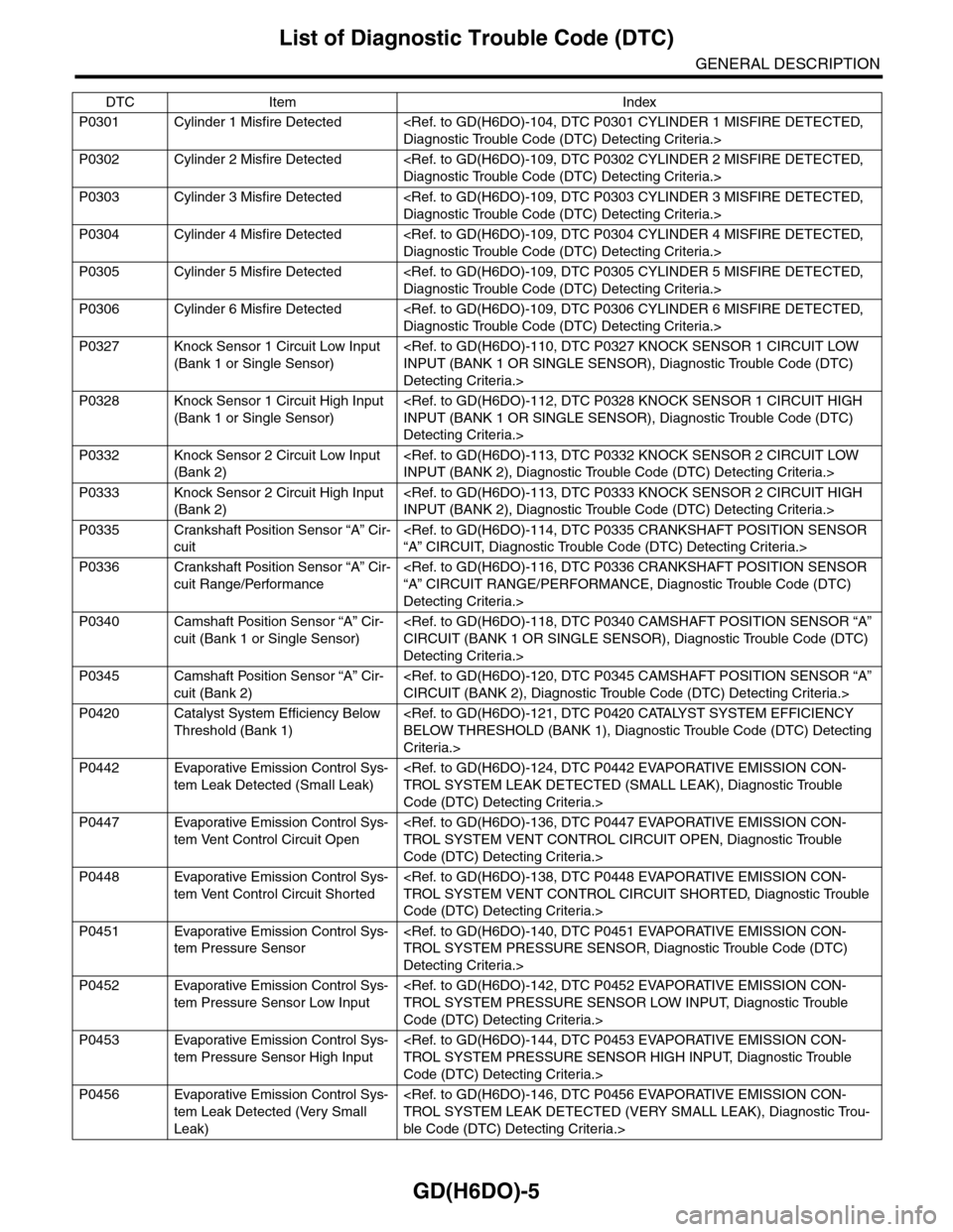
P0335 Crankshaft Position Sensor “A” Cir-
cuit
P0336 Crankshaft Position Sensor “A” Cir-
cuit Range/Performance
Detecting Criteria.>
P0340 Camshaft Position Sensor “A” Cir-
cuit (Bank 1 or Single Sensor)
Detecting Criteria.>
P0345 Camshaft Position Sensor “A” Cir-
cuit (Bank 2)
P0420 Catalyst System Efficiency Below
Threshold (Bank 1)
Criteria.>
P0442 Evaporative Emission Control Sys-
tem Leak Detected (Small Leak)
Code (DTC) Detecting Criteria.>
P0447 Evaporative Emission Control Sys-
tem Vent Control Circuit Open
Code (DTC) Detecting Criteria.>
P0448 Evaporative Emission Control Sys-
tem Vent Control Circuit Shorted
Code (DTC) Detecting Criteria.>
P0451 Evaporative Emission Control Sys-
tem Pressure Sensor
Detecting Criteria.>
P0452 Evaporative Emission Control Sys-
tem Pressure Sensor Low Input
Code (DTC) Detecting Criteria.>
P0453 Evaporative Emission Control Sys-
tem Pressure Sensor High Input
Code (DTC) Detecting Criteria.>
P0456 Evaporative Emission Control Sys-
tem Leak Detected (Very Small
Leak)
ble Code (DTC) Detecting Criteria.>
DTC Item Index