2009 SUBARU TRIBECA cam sensor
[x] Cancel search: cam sensorPage 1196 of 2453
EN(H6DO)(diag)-35
Inspection Mode
ENGINE (DIAGNOSTICS)
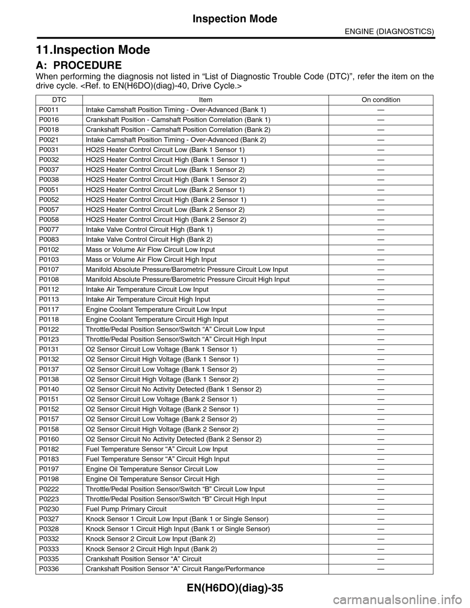
11.Inspection Mode
A: PROCEDURE
When performing the diagnosis not listed in “List of Diagnostic Trouble Code (DTC)”, refer the item on the
drive cycle.
DTC Item On condition
P0011 Intake Camshaft Position Timing - Over-Advanced (Bank 1) —
P0016 Crankshaft Position - Camshaft Position Correlation (Bank 1) —
P0018 Crankshaft Position - Camshaft Position Correlation (Bank 2) —
P0021 Intake Camshaft Position Timing - Over-Advanced (Bank 2) —
P0031 HO2S Heater Control Circuit Low (Bank 1 Sensor 1) —
P0032 HO2S Heater Control Circuit High (Bank 1 Sensor 1) —
P0037 HO2S Heater Control Circuit Low (Bank 1 Sensor 2) —
P0038 HO2S Heater Control Circuit High (Bank 1 Sensor 2) —
P0051 HO2S Heater Control Circuit Low (Bank 2 Sensor 1) —
P0052 HO2S Heater Control Circuit High (Bank 2 Sensor 1) —
P0057 HO2S Heater Control Circuit Low (Bank 2 Sensor 2) —
P0058 HO2S Heater Control Circuit High (Bank 2 Sensor 2) —
P0077 Intake Valve Control Circuit High (Bank 1) —
P0083 Intake Valve Control Circuit High (Bank 2) —
P0102 Mass or Volume Air Flow Circuit Low Input —
P0103 Mass or Volume Air Flow Circuit High Input —
P0107 Manifold Absolute Pressure/Barometric Pressure Circuit Low Input —
P0108 Manifold Absolute Pressure/Barometric Pressure Circuit High Input —
P0112 Intake Air Temperature Circuit Low Input —
P0113 Intake Air Temperature Circuit High Input —
P0117 Engine Coolant Temperature Circuit Low Input —
P0118 Engine Coolant Temperature Circuit High Input —
P0122 Throttle/Pedal Position Sensor/Switch “A” Circuit Low Input —
P0123 Throttle/Pedal Position Sensor/Switch “A” Circuit High Input —
P0131 O2 Sensor Circuit Low Voltage (Bank 1 Sensor 1) —
P0132 O2 Sensor Circuit High Voltage (Bank 1 Sensor 1) —
P0137 O2 Sensor Circuit Low Voltage (Bank 1 Sensor 2) —
P0138 O2 Sensor Circuit High Voltage (Bank 1 Sensor 2) —
P0140 O2 Sensor Circuit No Activity Detected (Bank 1 Sensor 2) —
P0151 O2 Sensor Circuit Low Voltage (Bank 2 Sensor 1) —
P0152 O2 Sensor Circuit High Voltage (Bank 2 Sensor 1) —
P0157 O2 Sensor Circuit Low Voltage (Bank 2 Sensor 2) —
P0158 O2 Sensor Circuit High Voltage (Bank 2 Sensor 2) —
P0160 O2 Sensor Circuit No Activity Detected (Bank 2 Sensor 2) —
P0182 Fuel Temperature Sensor “A” Circuit Low Input —
P0183 Fuel Temperature Sensor “A” Circuit High Input —
P0197 Engine Oil Temperature Sensor Circuit Low —
P0198 Engine Oil Temperature Sensor Circuit High —
P0222 Throttle/Pedal Position Sensor/Switch “B” Circuit Low Input —
P0223 Throttle/Pedal Position Sensor/Switch “B” Circuit High Input —
P0230 Fuel Pump Primary Circuit —
P0327 Knock Sensor 1 Circuit Low Input (Bank 1 or Single Sensor) —
P0328 Knock Sensor 1 Circuit High Input (Bank 1 or Single Sensor) —
P0332 Knock Sensor 2 Circuit Low Input (Bank 2) —
P0333 Knock Sensor 2 Circuit High Input (Bank 2) —
P0335 Crankshaft Position Sensor “A” Circuit —
P0336 Crankshaft Position Sensor “A” Circuit Range/Performance —
Page 1197 of 2453
EN(H6DO)(diag)-36
Inspection Mode
ENGINE (DIAGNOSTICS)
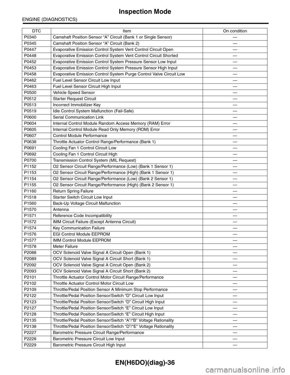
P0340 Camshaft Position Sensor “A” Circuit (Bank 1 or Single Sensor) —
P0345 Camshaft Position Sensor “A” Circuit (Bank 2) —
P0447 Evaporative Emission Control System Vent Control Circuit Open —
P0448 Evaporative Emission Control System Vent Control Circuit Shorted —
P0452 Evaporative Emission Control System Pressure Sensor Low Input —
P0453 Evaporative Emission Control System Pressure Sensor High Input —
P0458 Evaporative Emission Control System Purge Control Valve Circuit Low —
P0462 Fuel Level Sensor Circuit Low Input —
P0463 Fuel Level Sensor Circuit High Input —
P0500 Vehicle Speed Sensor—
P0512 Starter Request Circuit—
P0513 Incorrect Immobilizer Key —
P0519 Idle Control System Malfunction (Fail-Safe) —
P0600 Serial Communication Link —
P0604 Internal Control Module Random Access Memory (RAM) Error —
P0605 Internal Control Module Read Only Memory (ROM) Error —
P0607 Control Module Performance —
P0638 Throttle Actuator Control Range/Performance (Bank 1) —
P0691 Cooling Fan 1 Control Circuit Low —
P0692 Cooling Fan 1 Control Circuit High —
P0700 Transmission Control System (MIL Request) —
P1152 O2 Sensor Circuit Range/Performance (Low) (Bank 1 Sensor 1) —
P1153 O2 Sensor Circuit Range/Performance (High) (Bank 1 Sensor 1) —
P1154 O2 Sensor Circuit Range/Performance (Low) (Bank 2 Sensor 1) —
P1155 O2 Sensor Circuit Range/Performance (High) (Bank 2 Sensor 1) —
P1160 Return Spring Failure—
P1518 Starter Switch Circuit Low Input —
P1560 Back-Up Voltage Circuit Malfunction —
P1570 Antenna—
P1571 Reference Code Incompatibility —
P1572 IMM Circuit Failure (Except Antenna Circuit) —
P1574 Key Communication Failure —
P1576 EGI Control Module EEPROM —
P1577 IMM Control Module EEPROM —
P1578 Meter Failure—
P2088 OCV Solenoid Valve Signal A Circuit Open (Bank 1) —
P2089 OCV Solenoid Valve Signal A Circuit Short (Bank 1) —
P2092 OCV Solenoid Valve Signal A Circuit Open (Bank 2) —
P2093 OCV Solenoid Valve Signal A Circuit Short (Bank 2) —
P2101 Throttle Actuator Control Motor Circuit Range/Performance —
P2102 Throttle Actuator Control Motor Circuit Low —
P2109 Throttle/Pedal Position Sensor A Minimum Stop Performance —
P2122 Throttle/Pedal Position Sensor/Switch “D” Circuit Low Input —
P2123 Throttle/Pedal Position Sensor/Switch “D” Circuit High Input —
P2127 Throttle/Pedal Position Sensor/Switch “E” Circuit Low Input —
P2128 Throttle/Pedal Position Sensor/Switch “E” Circuit High Input —
P2135 Throttle/Pedal Position Sensor/Switch “A”/“B” Voltage Rationality —
P2138 Throttle/Pedal Position Sensor/Switch “D”/“E” Voltage Rationality —
P2227 Barometric Pressure Circuit Range/Performance —
P2228 Barometric Pressure Circuit Low Input —
P2229 Barometric Pressure Circuit High Input —
DTC Item On condition
Page 1230 of 2453
EN(H6DO)(diag)-69
List of Diagnostic Trouble Code (DTC)
ENGINE (DIAGNOSTICS)
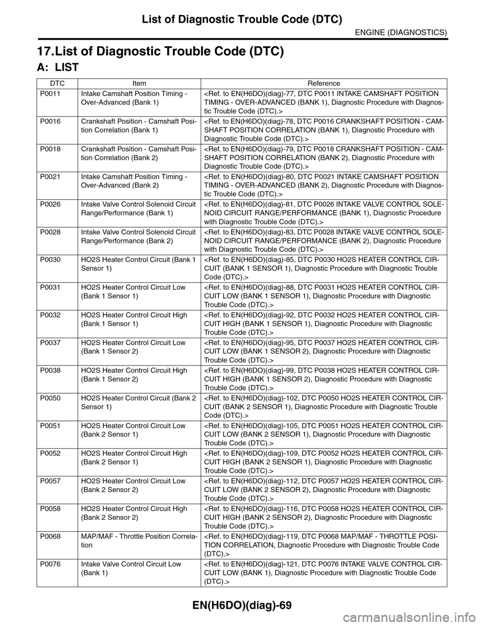
17.List of Diagnostic Trouble Code (DTC)
A: LIST
DTC Item Reference
P0011 Intake Camshaft Position Timing -
Over-Advanced (Bank 1)
tic Trouble Code (DTC).>
P0016 Crankshaft Position - Camshaft Posi-
tion Correlation (Bank 1)
Diagnostic Trouble Code (DTC).>
P0018 Crankshaft Position - Camshaft Posi-
tion Correlation (Bank 2)
Diagnostic Trouble Code (DTC).>
P0021 Intake Camshaft Position Timing -
Over-Advanced (Bank 2)
tic Trouble Code (DTC).>
P0026 Intake Valve Control Solenoid Circuit
Range/Performance (Bank 1)
with Diagnostic Trouble Code (DTC).>
P0028 Intake Valve Control Solenoid Circuit
Range/Performance (Bank 2)
with Diagnostic Trouble Code (DTC).>
P0030 HO2S Heater Control Circuit (Bank 1
Sensor 1)
Code (DTC).>
P0031 HO2S Heater Control Circuit Low
(Bank 1 Sensor 1)
Tr o u b l e C o d e ( D T C ) . >
P0032 HO2S Heater Control Circuit High
(Bank 1 Sensor 1)
Tr o u b l e C o d e ( D T C ) . >
P0037 HO2S Heater Control Circuit Low
(Bank 1 Sensor 2)
Tr o u b l e C o d e ( D T C ) . >
P0038 HO2S Heater Control Circuit High
(Bank 1 Sensor 2)
Tr o u b l e C o d e ( D T C ) . >
P0050 HO2S Heater Control Circuit (Bank 2
Sensor 1)
Code (DTC).>
P0051 HO2S Heater Control Circuit Low
(Bank 2 Sensor 1)
Tr o u b l e C o d e ( D T C ) . >
P0052 HO2S Heater Control Circuit High
(Bank 2 Sensor 1)
Tr o u b l e C o d e ( D T C ) . >
P0057 HO2S Heater Control Circuit Low
(Bank 2 Sensor 2)
Tr o u b l e C o d e ( D T C ) . >
P0058 HO2S Heater Control Circuit High
(Bank 2 Sensor 2)
Tr o u b l e C o d e ( D T C ) . >
P0068 MAP/MAF - Throttle Position Correla-
tion
(DTC).>
P0076 Intake Valve Control Circuit Low
(Bank 1)
(DTC).>
Page 1233 of 2453
EN(H6DO)(diag)-72
List of Diagnostic Trouble Code (DTC)
ENGINE (DIAGNOSTICS)
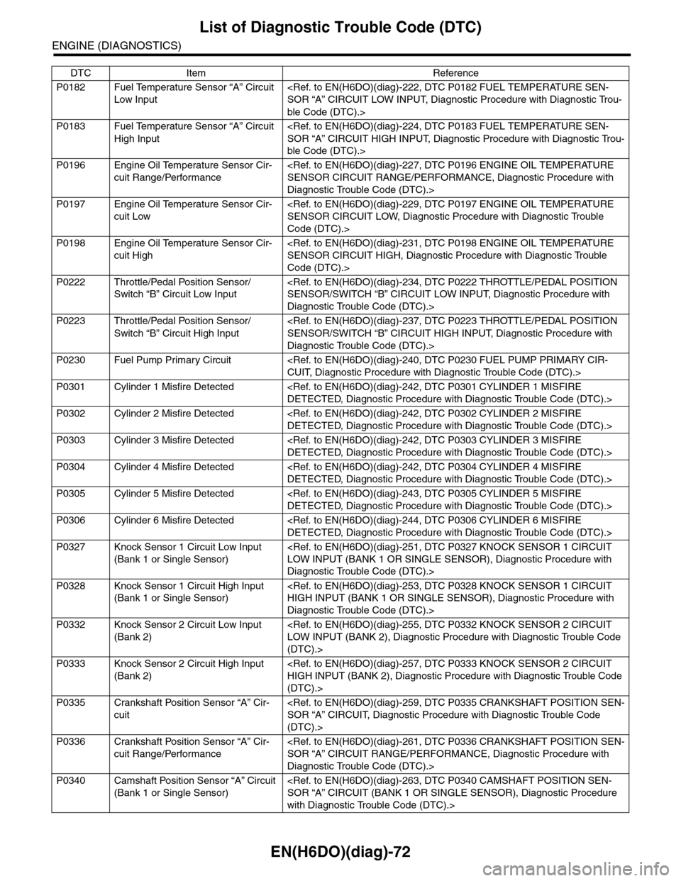
P0182 Fuel Temperature Sensor “A” Circuit
Low Input
ble Code (DTC).>
P0183 Fuel Temperature Sensor “A” Circuit
High Input
ble Code (DTC).>
P0196 Engine Oil Temperature Sensor Cir-
cuit Range/Performance
Diagnostic Trouble Code (DTC).>
P0197 Engine Oil Temperature Sensor Cir-
cuit Low
Code (DTC).>
P0198 Engine Oil Temperature Sensor Cir-
cuit High
Code (DTC).>
P0222 Throttle/Pedal Position Sensor/
Switch “B” Circuit Low Input
Diagnostic Trouble Code (DTC).>
P0223 Throttle/Pedal Position Sensor/
Switch “B” Circuit High Input
Diagnostic Trouble Code (DTC).>
P0230 Fuel Pump Primary Circuit
P0301 Cylinder 1 Misfire Detected
P0302 Cylinder 2 Misfire Detected
P0303 Cylinder 3 Misfire Detected
P0304 Cylinder 4 Misfire Detected
P0305 Cylinder 5 Misfire Detected
P0306 Cylinder 6 Misfire Detected
P0327 Knock Sensor 1 Circuit Low Input
(Bank 1 or Single Sensor)
Diagnostic Trouble Code (DTC).>
P0328 Knock Sensor 1 Circuit High Input
(Bank 1 or Single Sensor)
Diagnostic Trouble Code (DTC).>
P0332 Knock Sensor 2 Circuit Low Input
(Bank 2)
(DTC).>
P0333 Knock Sensor 2 Circuit High Input
(Bank 2)
(DTC).>
P0335 Crankshaft Position Sensor “A” Cir-
cuit
(DTC).>
P0336 Crankshaft Position Sensor “A” Cir-
cuit Range/Performance
Diagnostic Trouble Code (DTC).>
P0340 Camshaft Position Sensor “A” Circuit
(Bank 1 or Single Sensor)
with Diagnostic Trouble Code (DTC).>
DTC Item Reference
Page 1234 of 2453
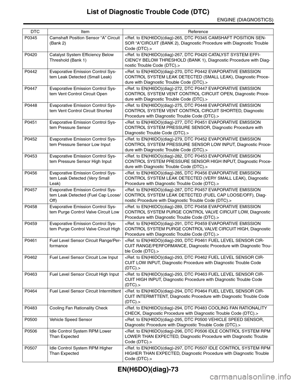
EN(H6DO)(diag)-73
List of Diagnostic Trouble Code (DTC)
ENGINE (DIAGNOSTICS)
P0345 Camshaft Position Sensor “A” Circuit
(Bank 2)
Code (DTC).>
P0420 Catalyst System Efficiency Below
Threshold (Bank 1)
nostic Trouble Code (DTC).>
P0442 Evaporative Emission Control Sys-
tem Leak Detected (Small Leak)
dure with Diagnostic Trouble Code (DTC).>
P0447 Evaporative Emission Control Sys-
tem Vent Control Circuit Open
dure with Diagnostic Trouble Code (DTC).>
P0448 Evaporative Emission Control Sys-
tem Vent Control Circuit Shorted
Procedure with Diagnostic Trouble Code (DTC).>
P0451 Evaporative Emission Control Sys-
tem Pressure Sensor
Diagnostic Trouble Code (DTC).>
P0452 Evaporative Emission Control Sys-
tem Pressure Sensor Low Input
dure with Diagnostic Trouble Code (DTC).>
P0453 Evaporative Emission Control Sys-
tem Pressure Sensor High Input
dure with Diagnostic Trouble Code (DTC).>
P0456 Evaporative Emission Control Sys-
tem Leak Detected (Very Small
Leak)
Procedure with Diagnostic Trouble Code (DTC).>
P0457 Evaporative Emission Control Sys-
tem Leak Detected (Fuel Cap Loose/
Off)
nostic Procedure with Diagnostic Trouble Code (DTC).>
P0458 Evaporative Emission Control Sys-
tem Purge Control Valve Circuit Low
Procedure with Diagnostic Trouble Code (DTC).>
P0459 Evaporative Emission Control Sys-
tem Purge Control Valve Circuit High
Procedure with Diagnostic Trouble Code (DTC).>
P0461 Fuel Level Sensor Circuit Range/Per-
for mance
ble Code (DTC).>
P0462 Fuel Level Sensor Circuit Low Input
(DTC).>
P0463 Fuel Level Sensor Circuit High Input
(DTC).>
P0464 Fuel Level Sensor Circuit Intermittent
(DTC).>
P0483 Cooling Fan Rationality Check
P0500 Vehicle Speed Sensor
P0506 Idle Control System RPM Lower
Than Expected
Code (DTC).>
P0507 Idle Control System RPM Higher
Than Expected
Code (DTC).>
DTC Item Reference
Page 1407 of 2453
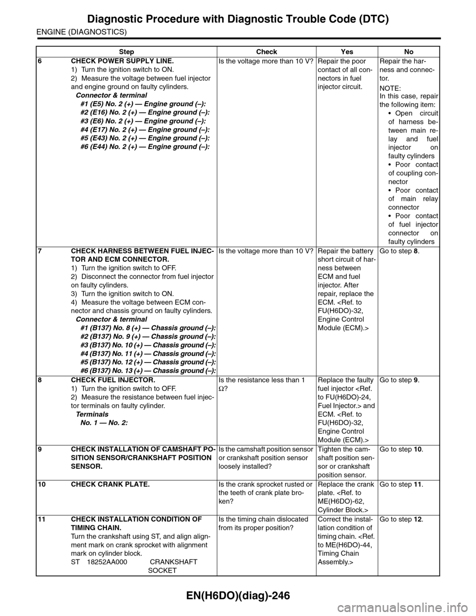
EN(H6DO)(diag)-246
Diagnostic Procedure with Diagnostic Trouble Code (DTC)
ENGINE (DIAGNOSTICS)
6CHECK POWER SUPPLY LINE.
1) Turn the ignition switch to ON.
2) Measure the voltage between fuel injector
and engine ground on faulty cylinders.
Connector & terminal
#1 (E5) No. 2 (+) — Engine ground (–):
#2 (E16) No. 2 (+) — Engine ground (–):
#3 (E6) No. 2 (+) — Engine ground (–):
#4 (E17) No. 2 (+) — Engine ground (–):
#5 (E43) No. 2 (+) — Engine ground (–):
#6 (E44) No. 2 (+) — Engine ground (–):
Is the voltage more than 10 V? Repair the poor
contact of all con-
nectors in fuel
injector circuit.
Repair the har-
ness and connec-
tor.
NOTE:In this case, repair
the following item:
•Open circuit
of harness be-
tween main re-
lay and fuel
injector on
faulty cylinders
•Poor contact
of coupling con-
nector
•Poor contact
of main relay
connector
•Poor contact
of fuel injector
connector on
faulty cylinders
7CHECK HARNESS BETWEEN FUEL INJEC-
TOR AND ECM CONNECTOR.
1) Turn the ignition switch to OFF.
2) Disconnect the connector from fuel injector
on faulty cylinders.
3) Turn the ignition switch to ON.
4) Measure the voltage between ECM con-
nector and chassis ground on faulty cylinders.
Connector & terminal
#1 (B137) No. 8 (+) — Chassis ground (–):
#2 (B137) No. 9 (+) — Chassis ground (–):
#3 (B137) No. 10 (+) — Chassis ground (–):
#4 (B137) No. 11 (+) — Chassis ground (–):
#5 (B137) No. 12 (+) — Chassis ground (–):
#6 (B137) No. 13 (+) — Chassis ground (–):
Is the voltage more than 10 V? Repair the battery
short circuit of har-
ness between
ECM and fuel
injector. After
repair, replace the
ECM.
Engine Control
Module (ECM).>
Go to step 8.
8CHECK FUEL INJECTOR.
1) Turn the ignition switch to OFF.
2) Measure the resistance between fuel injec-
tor terminals on faulty cylinder.
Te r m i n a l s
No. 1 — No. 2:
Is the resistance less than 1
Ω?
Replace the faulty
fuel injector
Fuel Injector.> and
ECM.
Engine Control
Module (ECM).>
Go to step 9.
9CHECK INSTALLATION OF CAMSHAFT PO-
SITION SENSOR/CRANKSHAFT POSITION
SENSOR.
Is the camshaft position sensor
or crankshaft position sensor
loosely installed?
Tighten the cam-
shaft position sen-
sor or crankshaft
position sensor.
Go to step 10.
10 CHECK CRANK PLATE.Is the crank sprocket rusted or
the teeth of crank plate bro-
ken?
Replace the crank
plate.
Cylinder Block.>
Go to step 11.
11 CHECK INSTALLATION CONDITION OF
TIMING CHAIN.
Tu r n t h e c r a n k s h a f t u s i n g S T, a n d a l i g n a l i g n -
ment mark on crank sprocket with alignment
mark on cylinder block.
ST 18252AA000 CRANKSHAFT
SOCKET
Is the timing chain dislocated
from its proper position?
Correct the instal-
lation condition of
timing chain.
Timing Chain
Assembly.>
Go to step 12.
Step Check Yes No
Page 1424 of 2453
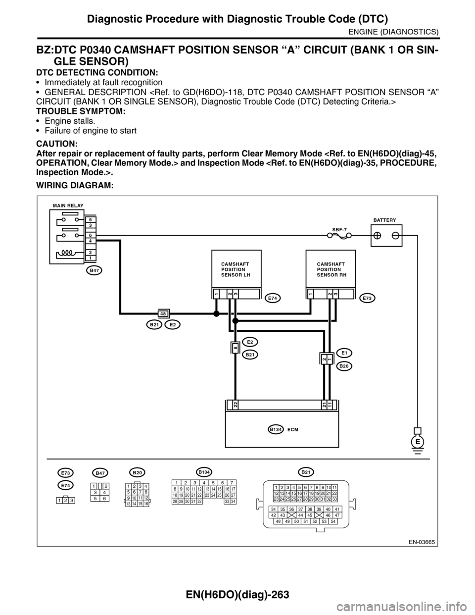
EN(H6DO)(diag)-263
Diagnostic Procedure with Diagnostic Trouble Code (DTC)
ENGINE (DIAGNOSTICS)
BZ:DTC P0340 CAMSHAFT POSITION SENSOR “A” CIRCUIT (BANK 1 OR SIN-
GLE SENSOR)
DTC DETECTING CONDITION:
•Immediately at fault recognition
•GENERAL DESCRIPTION
TROUBLE SYMPTOM:
•Engine stalls.
•Failure of engine to start
CAUTION:
After repair or replacement of faulty parts, perform Clear Memory Mode
WIRING DIAGRAM:
EN-03665
B47
12
46
35
E
E2
B21
3
22
SBF-7
E74
E1
B20
2E73
B21E2
1
6
3
11
21
ECMB134
48
1
3412
56
B20
E74
B47
123
E73
BATTERY
CAMSHAFTPOSITIONSENSOR RH
CAMSHAFTPOSITIONSENSOR LH
MAIN RELAY
2
21
B21
123412131415567816171819910 1120212223 24 25 2627 28 29 3031 32 33
3534 37363938 41404342 4445 47464948 51505352 54
1234567891011 121314 15 16
B134
85610 11 12 13 14 157213416
3019 20 2228 29
91718252123 24323126 2733 34
Page 1425 of 2453
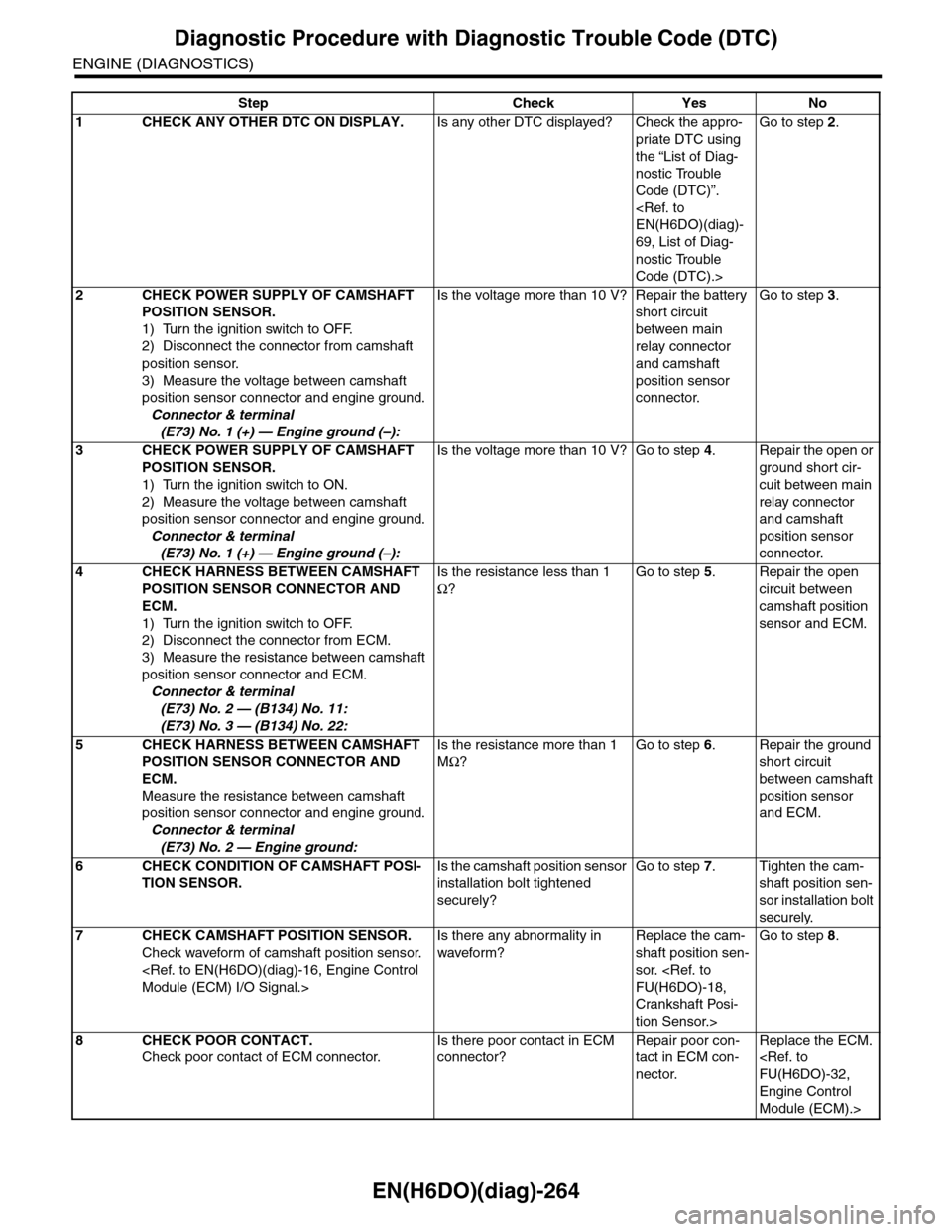
EN(H6DO)(diag)-264
Diagnostic Procedure with Diagnostic Trouble Code (DTC)
ENGINE (DIAGNOSTICS)
Step Check Yes No
1CHECK ANY OTHER DTC ON DISPLAY.Is any other DTC displayed? Check the appro-
priate DTC using
the “List of Diag-
nostic Trouble
Code (DTC)”.
69, List of Diag-
nostic Trouble
Code (DTC).>
Go to step 2.
2CHECK POWER SUPPLY OF CAMSHAFT
POSITION SENSOR.
1) Turn the ignition switch to OFF.
2) Disconnect the connector from camshaft
position sensor.
3) Measure the voltage between camshaft
position sensor connector and engine ground.
Connector & terminal
(E73) No. 1 (+) — Engine ground (–):
Is the voltage more than 10 V? Repair the battery
short circuit
between main
relay connector
and camshaft
position sensor
connector.
Go to step 3.
3CHECK POWER SUPPLY OF CAMSHAFT
POSITION SENSOR.
1) Turn the ignition switch to ON.
2) Measure the voltage between camshaft
position sensor connector and engine ground.
Connector & terminal
(E73) No. 1 (+) — Engine ground (–):
Is the voltage more than 10 V? Go to step 4.Repair the open or
ground short cir-
cuit between main
relay connector
and camshaft
position sensor
connector.
4CHECK HARNESS BETWEEN CAMSHAFT
POSITION SENSOR CONNECTOR AND
ECM.
1) Turn the ignition switch to OFF.
2) Disconnect the connector from ECM.
3) Measure the resistance between camshaft
position sensor connector and ECM.
Connector & terminal
(E73) No. 2 — (B134) No. 11:
(E73) No. 3 — (B134) No. 22:
Is the resistance less than 1
Ω?
Go to step 5.Repair the open
circuit between
camshaft position
sensor and ECM.
5CHECK HARNESS BETWEEN CAMSHAFT
POSITION SENSOR CONNECTOR AND
ECM.
Measure the resistance between camshaft
position sensor connector and engine ground.
Connector & terminal
(E73) No. 2 — Engine ground:
Is the resistance more than 1
MΩ?
Go to step 6.Repair the ground
short circuit
between camshaft
position sensor
and ECM.
6CHECK CONDITION OF CAMSHAFT POSI-
TION SENSOR.
Is the camshaft position sensor
installation bolt tightened
securely?
Go to step 7.Tighten the cam-
shaft position sen-
sor installation bolt
securely.
7CHECK CAMSHAFT POSITION SENSOR.
Check waveform of camshaft position sensor.
Is there any abnormality in
waveform?
Replace the cam-
shaft position sen-
sor.
Crankshaft Posi-
tion Sensor.>
Go to step 8.
8CHECK POOR CONTACT.
Check poor contact of ECM connector.
Is there poor contact in ECM
connector?
Repair poor con-
tact in ECM con-
nector.
Replace the ECM.
Engine Control
Module (ECM).>