2009 SUBARU TRIBECA boot
[x] Cancel search: bootPage 907 of 2453

PS-27
Steering Gearbox
POWER ASSISTED SYSTEM (POWER STEERING)
22) Tighten the adjusting screw to the specified
torque.
Tightening torque:
3.9 N·m (0.4 kgf-m, 2.9 ft-lb)
23) Tighten the adjusting screw to the specified
torque, then loosen it 20°.
24) Remove the tie–rod.
25) Adjust the turning resistance of gearbox so that
it is within specification using adjusting screw.
26) Apply liquid gasket to lock nut and install it into
adjusting screw. While holding the adjusting screw
with wrench, tighten the lock nut using ST.
Liquid gasket:
THREE BOND 1141
ST 926230000 SPANNER
Tightening torque (lock nut):
25 N·m (2.5 kgf-m, 18.1 ft-lb)
NOTE:
Hold the adjusting screw with a wrench to prevent it
from turning while tightening lock nut.
27) Extend the rack approx. 40 mm (1.57 in) from
steering body.
28) Install the tie-rod and new lock washer into
rack.
Tightening torque:
130 N·m (13.3 kgf-m, 95.9 ft-lb)
29) Bend the lock washer and caulk it.
CAUTION:
Be careful not to scratch the rack when caulk-
ing lock washer.
30) Apply a coat of grease to the tie–rod groove,
and then install the boot to the housing.
CAUTION:
Right side boot has groove for identification, be
sure to install the right and left of boot.
(1) Lock washer
(2) Approx. 40 mm (1.57 in)
PS-00439
(2)
(1)
(1) Lock washer
(1) Right side boot
(2) Groove for identification
PS-00093
PS-00524
(2)
(1)
Page 908 of 2453

PS-28
Steering Gearbox
POWER ASSISTED SYSTEM (POWER STEERING)
NOTE:
Make sure that the boot is installed without unusual
inflation or deflation.
31) Install a new boot band. Using band clamp pli-
ers, caulk it so that the clearance of caulking por-
tion becomes 2mm (0. 079 in) or less.
32) Fix the boot end with small clip.
33) After installing, check that the boot end is in-
stalled to the groove of the tie–rod.
34) If the tie-rod end has been removed, screw in
lock nut and tie-rod end to the screwed portion of
tie–rod, and tighten the lock nut temporarily in a po-
sition as shown in the figure.
Installed tie-rod length L:
31 mm (1.22 in)
35) Inspect the gearbox as follows:
Holding the “A” tie–rod end, repeat movement from
lock to lock two or three times as quickly as possi-
ble.
Holding the “B” tie–rod end, turn a few times as
slowly as possible.
Finally, make sure that the boot is installed in the
specified position without inflating.
36) Remove the gearbox from ST.
ST1 926200000 STAND
ST2 34199AG000 BOSS D
(A) Boot band
(B) Less than 2 mm (0.079 in)
PS-00194
PS-00499
(A)
(B)
(1) Clip
PS-00053
PS-00097
L
PS-00098
BA
Page 913 of 2453

PS-33
Steering Gearbox
POWER ASSISTED SYSTEM (POWER STEERING)
E: INSPECTION
1. BASIC INSPECTION
1) Clean all the disassembled parts, and check for wear, damage or any other faults, then repair or replace
as necessary.
2) When disassembling, check the inside of gearbox for water. If any water is found, carefully check the boot
for damage, input shaft dust seal, adjusting screw and boot clips for poor sealing. If faulty, replace with new
parts.
No. Parts Inspection Corrective action
1Input shaft(1) Bent input shaft
(2) Damage on serration
If the bend or damage is excessive, replace the entire
gearbox.
2Dust seal(1) Crack or damage
(2) Wear
If the outer wall slips, the lip is worn out or damage is
found, replace it with a new one.
3Rack & pinion Poor mating of rack with pinion
(1) Adjust the backlash properly.
By measuring the turning torque of the gearbox and slid-
ing resistance of rack, check if the rack & pinion engage
uniformly and smoothly with each other. (Refer to “Ser-
vice limit”.)
(2) Pull out the entire rack to allow viewing of the teeth,
and check for damage.
Even if abnormality is found in either (1) or (2), replace
the entire gearbox.
4Gearbox unit
(1) Bending of the rack shaft
(2) Bending of the cylinder portion
(3) Crack or damage on the cast
iron portion
Replace the gearbox with a new one.
(4) Wear or damage on rack bush-
ing
If the free play of rack shaft in radial direction is out of the
specified range, replace the gearbox with new one. (Refer
to “Service limit”.)
(5) Wear on input shaft bearing
If the free play of input shaft in radial and axial direction is
out of the specified range, replace the gearbox with a new
one. (Refer to “Service limit”.)
5Boot Crack, damage or deteriorationReplace.
6Tie–rod(1) Looseness of ball joint
(2) Bend of tie–rodReplace.
7Tie–rod endDamage or deterioration of dust
sealReplace.
8Adjusting screw
springDeterioration Replace.
9Boot clip Deterioration Replace.
10 Sleeve Damage Replace.
11 Pipe
(1) Damage to flared surface
(2) Damage to flare nut
(3) Damage to pipe
Replace.
Page 916 of 2453

PS-36
Steering Gearbox
POWER ASSISTED SYSTEM (POWER STEERING)
1) Lift-up the vehicle.
2) If a fluid leak is found, clean the fluid completely
from the suspect area, and turn the steering wheel
approx. 30 to 40 times to the left and right from lock
to lock, with the engine running, and check again
for leaks immediately, and also after a few hours
have passed.
3) Cause and solution for oil leakage from “a”
The oil seal is damaged. Replace the valve assem-
bly with a new one.
4) Cause and solution for oil leakage from “b”.
The torsion bar O–ring is damaged. Replace the
valve assembly with a new one.
5) Cause and solution for oil leakage from “c”.
The oil seal is damaged. Replace the valve assem-
bly or oil seal with a new one.
6) Cause and solution for oil leakage from “d”.
The pipe is damaged. Replace the faulty pipe or O-
ring.
7) Cause and solution for oil leakage from “g”.
The hose is damaged. Replace the hose with a
new one.
8) If leak is other than a, b, c, d or g, or if oil is leak-
ing from gearbox, move the right and left boots to-
ward tie-rod end side, respectively, with the
gearbox mounted to the vehicle, and remove fluid
from surrounding portions. Then, turn the steering
wheel from lock to lock about thirty to forty times
with the engine running, and make comparison of
the leaked portion immediately after and several
hours after this operation.
(1) Leakage from “e”
The cylinder seal is damaged. Replace the rack
bushing with a new one.
(2) Leakage from “f”
There are two possible causes. Perform the fol-
lowing step first. Remove the pipe assembly B
from the valve housing, and close the circuit us-
ing ST.
ST 926420000 PLUG
Turn the steering wheel from lock to lock ap-
prox. 30 to 40 times with the engine running,
then inspect the leaked portion immediately af-
ter and several hours after this operation.
•If leakage from “f” is noted again:
The oil seal of pinion & valve assembly is dam-
aged. Replace the pinion & valve assembly with a
new one. Or replace the oil seal and the parts that
are damaged during disassembly with new ones.
•If oil stops leaking from “f”:
The oil seal of rack housing is damaged. Replace
the oil seal and parts that are damaged during dis-
assembly with new ones.
F: ADJUSTMENT
1) Adjust the front toe.
Standard of front toe:
IN 3 — OUT 3 mm (IN 0.12 — OUT 0.12 in)
2) Adjust the steering angle of the wheels.
Specification of steering angle:
3) If the steering wheel spokes are not horizontal
when wheels are set in the straight ahead position,
or error is more than 5° on the periphery of the
steering wheel, correctly re-install the steering
wheel.
4) If the steering wheel spokes are not horizontal
with vehicle set in the straight ahead position after
this adjustment, correct it by turning the right and
left tie–rods in the opposite direction from each oth-
er by the same angle.
(1) Lock nut
Inner wheel 37.0°±1.5°
Outer wheel 32.0°±1.5°
(1) Within 5°
PS-00107
PS-00513
(1)
Page 933 of 2453

PS-53
General Diagnostic Table
POWER ASSISTED SYSTEM (POWER STEERING)
3. INSPECTION OF CLEARANCE
This table lists various clearances that must be correctly adjusted to ensure the normal vehicle driving with-
out interfering noise, or any other faults.
Install locations Minimum allowance mm (in)
(1) Crossmember-to-Hose assembly 10 (0.39)
(2) Front frame side-to-Hose assembly 15 (0.59)
(3) Air bag sensor to cooler pipe assembly 10 (0.39)
(4) Air cleaner case-to-Suction hose 10 (0.39)
(5) VDCH/U to Reservoir tank bracket 10 (0.39)
(6) Air boots to Hose clip15 (0.59)
(7) Air boot-to-Hose assembly15 (0.59)
(8) Protector to Hose assembly10 (0.39)
(9) Intake manifold to Suction hose 10 (0.39)
(10) Intake manifold to hose assembly 10 (0.39)
(11) Air cleaner case to Cooler pipe joint block 5 (0.20)
(12) Chain cover to Cooler pipe joint block 20 (0.79)
(13) Oil pipe to Cooler pipe joint block 20 (0.79)
(14) Suction hose to Hose assembly 10 (0.39)
(15) Air boot to Reservoir tank10 (0.39)
(16) Brake pipe to Reservoir tank10 (0.39)
(17) Harness to Hose assembly10 (0.39)
(18) Relay box to Hose assembly15 (0.59)
(19) Bumper beam to Cooler pipe assembly 10 (0.39)
(20) Radiator bracket to Cooler pipe assembly 10 (0.39)
(21) ATF cooler to Cooler pipe assembly 10 (0.39)
(22) Undercover to cooler pipe assembly 10 (0.39)
(23) Protector to Hose assembly10 (0.39)
(24) Protector to Hose assembly15 (0.59)
(25) Return hose to Hose assembly 10 (0.39)
(26) Air cleaner case to Hose assembly 10 (0.39)
(27) Suction hose to Hose assembly 10 (0.39)
(28) Air cleaner case to Return hose 3 (0.12)
(29) Valve housing to DOJ12 (0.47)
(30) Valve housing to Crossmember 1 (0.04)
(31) Mount to Crossmember There must be no contact.
(32) Feed tube to Crossmember3 (0.12)
(33) Elbow to Crossmember3 (0.12)
(34) Cylinder pipe to Crossmember 3 (0.12)
(35) Feed tube to Exhaust pipe18 (0.71)
(36) Tie-rod end to Brake dust cover 2.5 (0.10)
(37) Coupling rubber to AT level gage 10 (0.39)
(38) Yoke to Brake booster5 (0.20)
Page 1986 of 2453

PM-3
Schedule
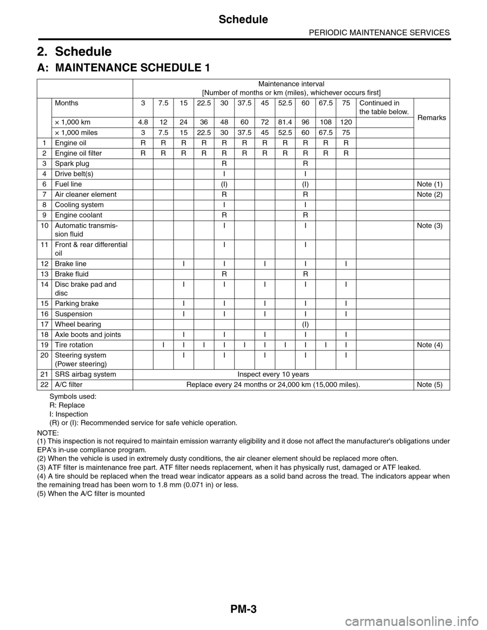
PERIODIC MAINTENANCE SERVICES
2. Schedule
A: MAINTENANCE SCHEDULE 1
Symbols used:
R: Replace
I: Inspection
(R) or (I): Recommended service for safe vehicle operation.
NOTE:(1) This inspection is not required to maintain emission warranty eligibility and it dose not affect the manufacturer's obligations under
EPA's in-use compliance program.
(2) When the vehicle is used in extremely dusty conditions, the air cleaner element should be replaced more often.
(3) ATF filter is maintenance free part. ATF filter needs replacement, when it has physically rust, damaged or ATF leaked.
(4) A tire should be replaced when the tread wear indicator appears as a solid band across the tread. The indicators appear when
the remaining tread has been worn to 1.8 mm (0.071 in) or less.
(5) When the A/C filter is mounted
Maintenance interval
[Number of months or km (miles), whichever occurs first]
Months 3 7.51522.53037.54552.56067.575Continued in
the table below.Remarks× 1,000 km 4.8 12 24 36 48 60 72 81.4 96 108 120
× 1,000 miles 3 7.5 15 22.5 30 37.5 45 52.5 60 67.5 75
1Engine oil R R R R R R R R R R R
2Engine oil filter R R R R R R R R R R R
3Spark plug R R
4Drive belt(s) I I
6Fuel line (I) (I) Note (1)
7Air cleaner element R R Note (2)
8Cooling system I I
9Engine coolant R R
10 Automatic transmis-
sion fluid
I I Note (3)
11 Front & rear differential
oil
I I
12 Brake line I I I I I
13 Brake fluid R R
14 Disc brake pad and
disc
I I I I I
15 Parking brake I I I I I
16 Suspension I I I I I
17 Wheel bearing (I)
18 Axle boots and joints I I I I I
19 Tire rotation I I I I I I I I I I Note (4)
20 Steering system
(Power steering)
I I I I I
21 SRS airbag system Inspect every 10 years
22 A/C filter Replace every 24 months or 24,000 km (15,000 miles). Note (5)
Page 1987 of 2453

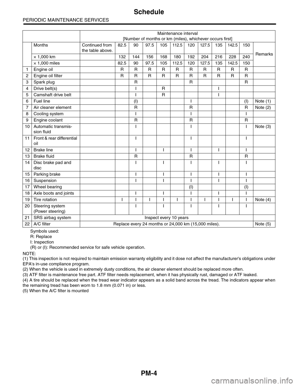
PM-4
Schedule
PERIODIC MAINTENANCE SERVICES
Symbols used:
R: Replace
I: Inspection
(R) or (I): Recommended service for safe vehicle operation.
NOTE:(1) This inspection is not required to maintain emission warranty eligibility and it dose not affect the manufacturer's obligations under
EPA's in-use compliance program.
(2) When the vehicle is used in extremely dusty conditions, the air cleaner element should be replaced more often.
(3) ATF filter is maintenance free part. ATF filter needs replacement, when it has physically rust, damaged or ATF leaked.
(4) A tire should be replaced when the tread wear indicator appears as a solid band across the tread. The indicators appear when
the remaining tread has been worn to 1.8 mm (0.071 in) or less.
(5) When the A/C filter is mounted
Maintenance interval
[Number of months or km (miles), whichever occurs first]
Months Continued from
the table above.
82.5 90 97.5 105112.5120127.5135142.5150
Remarks× 1,000 km 132 144 156 168 180 192 204 216 228 240
× 1,000 miles 82.5 90 97.5 105112.5120127.5135142.5150
1Engine oil R R R R R R R R R R
2Engine oil filter R R R R R R R R R R
3Spark plug R R R
4Drive belt(s) I R I
5Camshaft drive belt I R I
6Fuel line (I) I (I) Note (1)
7Air cleaner element R R R Note (2)
8Cooling system I I I
9Engine coolant R R R
10 Automatic transmis-
sion fluid
I I INote (3)
11 Front & rear differential
oil
I I I
12 Brake line I I I I I
13 Brake fluid R R R
14 Disc brake pad and
disc
I I I I I
15 Parking brake I I I I I
16 Suspension I I I I I
17 Wheel bearing (I) (I)
18 Axle boots and joints I I I I I
19 Tire rotation I I I I I I I I I I Note (4)
20 Steering system
(Power steering)
I I I I I
21 SRS airbag system Inspect every 10 years
22 A/C filter Replace every 24 months or 24,000 km (15,000 miles). Note (5)
Page 1988 of 2453

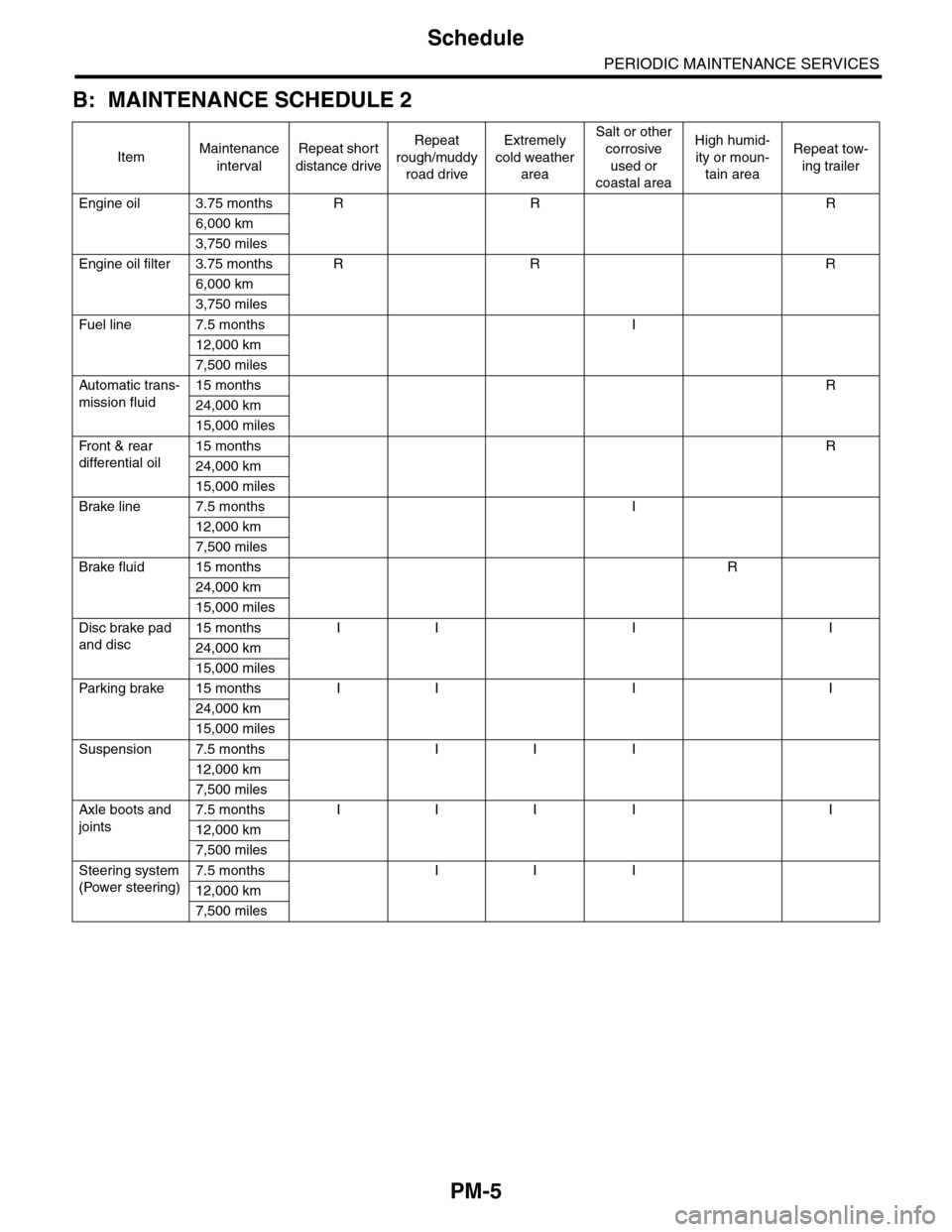
PM-5
Schedule
PERIODIC MAINTENANCE SERVICES
B: MAINTENANCE SCHEDULE 2
ItemMaintenance
interval
Repeat short
distance drive
Repeat
rough/muddy
road drive
Extremely
cold weather
area
Salt or other
corrosive
used or
coastal area
High humid-
ity or moun-
tain area
Repeat tow-
ing trailer
Engine oil 3.75 months R R R
6,000 km
3,750 miles
Engine oil filter 3.75 months R R R
6,000 km
3,750 miles
Fuel line 7.5 months I
12,000 km
7,500 miles
Automatic trans-
mission fluid
15 months R
24,000 km
15,000 miles
Fr o nt & r ea r
differential oil
15 months R
24,000 km
15,000 miles
Brake line 7.5 months I
12,000 km
7,500 miles
Brake fluid 15 months R
24,000 km
15,000 miles
Disc brake pad
and disc
15 months I I I I
24,000 km
15,000 miles
Par king brake 15 months I I I I
24,000 km
15,000 miles
Suspension 7.5 months I I I
12,000 km
7,500 miles
Axle boots and
joints
7.5 months I I I I I
12,000 km
7,500 miles
Steering system
(Power steering)
7.5 months I I I
12,000 km
7,500 miles