2009 SUBARU TRIBECA jack point
[x] Cancel search: jack pointPage 1845 of 2453
IN(H6DO)-3
General Description
INTAKE (INDUCTION)
B: CAUTION
•Wear work clothing, including a cap, protective
goggles and protective shoes during operation.
•Remove contamination including dirt and corro-
sion before removal, installation or disassembly.
•Keep the disassembled parts in order and pro-
tect them from dust and dirt.
•Before removal, installation or disassembly, be
sure to clarify the failure. Avoid unnecessary re-
moval, installation, disassembly and replacement.
•Be careful not to burn yourself, because each
part on the vehicle is hot after running.
•Be sure to tighten fasteners including bolts and
nuts to the specified torque.
•Place shop jacks or rigid racks at the specified
points.
•Before disconnecting connectors of sensors or
units, be sure to disconnect the ground cable from
the battery.
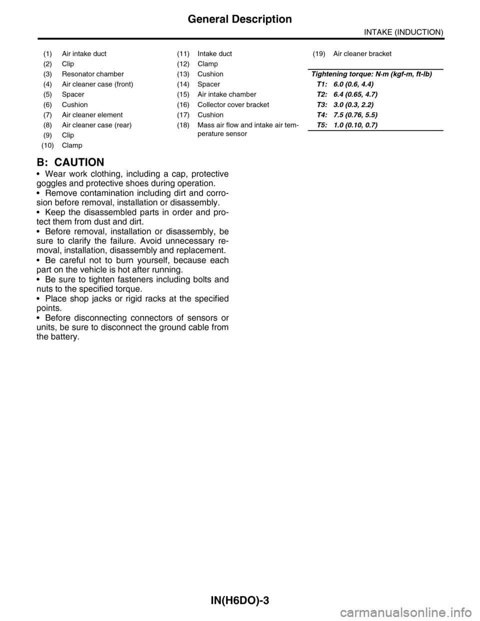
(1) Air intake duct (11) Intake duct (19) Air cleaner bracket
(2) Clip (12) Clamp
(3) Resonator chamber (13) CushionTightening torque: N·m (kgf-m, ft-lb)
(4) Air cleaner case (front) (14) SpacerT1: 6.0 (0.6, 4.4)
(5) Spacer (15) Air intake chamberT2: 6.4 (0.65, 4.7)
(6) Cushion (16) Collector cover bracketT3: 3.0 (0.3, 2.2)
(7) Air cleaner element (17) CushionT4: 7.5 (0.76, 5.5)
(8) Air cleaner case (rear) (18) Mass air flow and intake air tem-
perature sensor
T5: 1.0 (0.10, 0.7)
(9) Clip
(10) Clamp
Page 1853 of 2453
LU(H6DO)-4
General Description
LUBRICATION
C: CAUTION
•Wear work clothing, including a cap, protective goggles and protective shoes during operation.
•Remove contamination including dirt and corrosion before removal, installation or disassembly.
•Keep the disassembled parts in order and protect them from dust and dirt.
•Before removal, installation or disassembly, be sure to clarify the failure. Avoid unnecessary removal, in-
stallation, disassembly and replacement.
•Be careful not to burn yourself, because each part on the vehicle is hot after running.
•Be sure to tighten fasteners including bolts and nuts to the specified torque.
•Place shop jacks or rigid racks at the specified points.
•Before disconnecting connectors of sensors or units, be sure to disconnect the ground cable from battery.
D: PREPARATION TOOL
1. SPECIAL TOOL
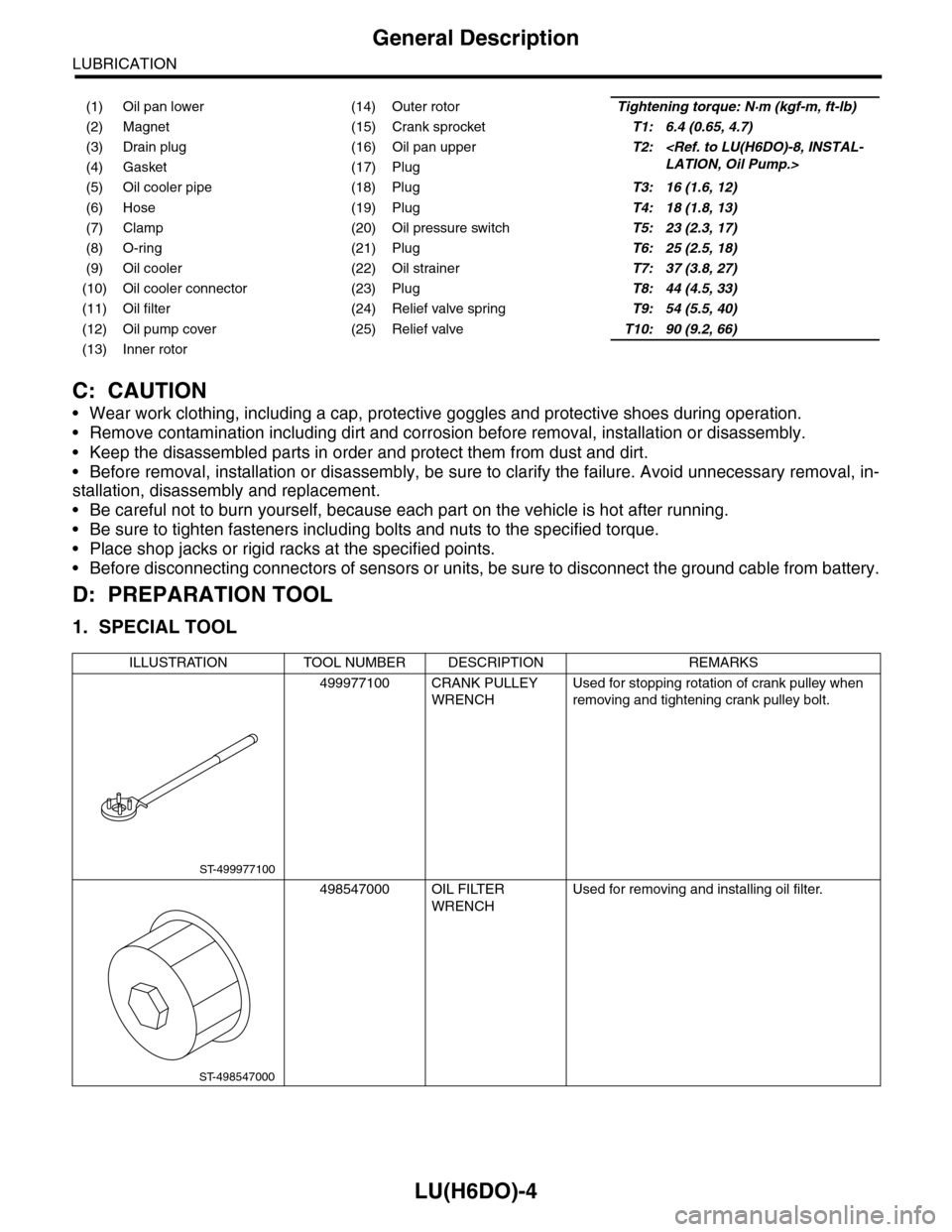
(1) Oil pan lower (14) Outer rotorTightening torque: N·m (kgf-m, ft-lb)
(2) Magnet (15) Crank sprocketT1: 6.4 (0.65, 4.7)
(3) Drain plug (16) Oil pan upperT2:
(5) Oil cooler pipe (18) PlugT3: 16 (1.6, 12)
(6) Hose (19) PlugT4: 18 (1.8, 13)
(7) Clamp (20) Oil pressure switchT5: 23 (2.3, 17)
(8) O-ring (21) PlugT6: 25 (2.5, 18)
(9) Oil cooler (22) Oil strainerT7: 37 (3.8, 27)
(10) Oil cooler connector (23) PlugT8: 44 (4.5, 33)
(11) Oil filter (24) Relief valve springT9: 54 (5.5, 40)
(12) Oil pump cover (25) Relief valveT10: 90 (9.2, 66)
(13) Inner rotor
ILLUSTRATION TOOL NUMBER DESCRIPTION REMARKS
499977100 CRANK PULLEY
WRENCH
Used for stopping rotation of crank pulley when
removing and tightening crank pulley bolt.
498547000 OIL FILTER
WRENCH
Used for removing and installing oil filter.
ST-499977100
ST-498547000
Page 1880 of 2453
ME(H6DO)-14
General Description
MECHANICAL
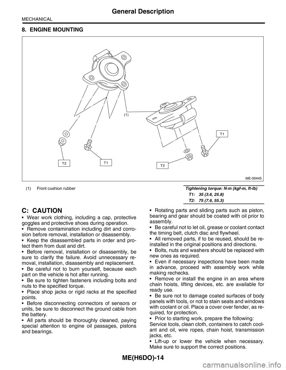
8. ENGINE MOUNTING
C: CAUTION
•Wear work clothing, including a cap, protective
goggles and protective shoes during operation.
•Remove contamination including dirt and corro-
sion before removal, installation or disassembly.
•Keep the disassembled parts in order and pro-
tect them from dust and dirt.
•Before removal, installation or disassembly, be
sure to clarify the failure. Avoid unnecessary re-
moval, installation, disassembly and replacement.
•Be careful not to burn yourself, because each
part on the vehicle is hot after running.
•Be sure to tighten fasteners including bolts and
nuts to the specified torque.
•Place shop jacks or rigid racks at the specified
points.
•Before disconnecting connectors of sensors or
units, be sure to disconnect the ground cable from
the battery.
•All parts should be thoroughly cleaned, paying
special attention to engine oil passages, pistons
and bearings.
•Rotating parts and sliding parts such as piston,
bearing and gear should be coated with oil prior to
assembly.
•Be careful not to let oil, grease or coolant contact
the timing belt, clutch disc and flywheel.
•All removed parts, if to be reused, should be re-
installed in the original positions and directions.
•Bolts, nuts and washers should be replaced with
new ones as required.
•Even if necessary inspections have been made
in advance, proceed with assembly work while
making rechecks.
•Remove or install the engine in an area where
chain hoists, lifting devices, etc. are available for
ready use.
•Be sure not to damage coated surfaces of body
panels with tools, or not to stain seats and windows
with coolant or oil. Place a cover over fender, as re-
quired, for protection.
•Prior to starting work, prepare the following:
Service tools, clean cloth, containers to catch cool-
ant and oil, wire ropes, chain hoist, transmission
jacks, etc.
•Lift-up or lower the vehicle when necessary.
Make sure to support the correct positions.
(1) Front cushion rubber Tightening torque: N·m (kgf-m, ft-lb)
T1: 35 (3.6, 25.8)
T2: 75 (7.6, 55.3)
(1)
T2
T1
T1T2
ME-00445
Page 1957 of 2453
SP(H6DO)-2
General Description
SPEED CONTROL SYSTEMS
1. General Description
A: SPECIFICATION
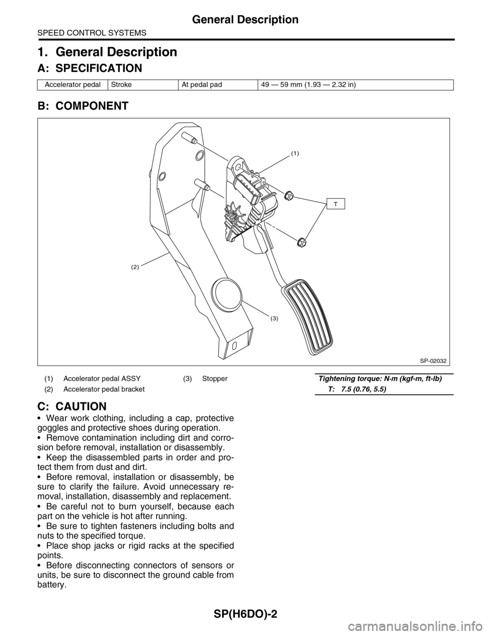
B: COMPONENT
C: CAUTION
•Wear work clothing, including a cap, protective
goggles and protective shoes during operation.
•Remove contamination including dirt and corro-
sion before removal, installation or disassembly.
•Keep the disassembled parts in order and pro-
tect them from dust and dirt.
•Before removal, installation or disassembly, be
sure to clarify the failure. Avoid unnecessary re-
moval, installation, disassembly and replacement.
•Be careful not to burn yourself, because each
part on the vehicle is hot after running.
•Be sure to tighten fasteners including bolts and
nuts to the specified torque.
•Place shop jacks or rigid racks at the specified
points.
•Before disconnecting connectors of sensors or
units, be sure to disconnect the ground cable from
battery.
Accelerator pedal Stroke At pedal pad 49 — 59 mm (1.93 — 2.32 in)
(1) Accelerator pedal ASSY (3) StopperTightening torque: N·m (kgf-m, ft-lb)
(2) Accelerator pedal bracket T: 7.5 (0.76, 5.5)
SP-02032
(1)
(2)
(3)
T
Page 1963 of 2453
SC(H6DO)-5
General Description
STARTING/CHARGING SYSTEMS
C: CAUTION
•Wear work clothing, including a cap, protective
goggles and protective shoes during operation.
•Remove contamination including dirt and corro-
sion before removal, installation or disassembly.
•Keep the disassembled parts in order and pro-
tect them from dust and dirt.
•Before removal, installation or disassembly, be
sure to clarify the failure. Avoid unnecessary re-
moval, installation, disassembly and replacement.
•Be careful not to burn yourself, because each
part on the vehicle is hot after running.
•Be sure to tighten fasteners including bolts and
nuts to the specified torque.
•Place shop jacks or rigid racks at the specified
points.
•Before disconnecting connectors of sensors or
units, be sure to disconnect the ground cable from
battery.
Page 2005 of 2453
PM-22
Disc Brake Pad & Disc
PERIODIC MAINTENANCE SERVICES
15.Disc Brake Pad & Disc
A: INSPECTION
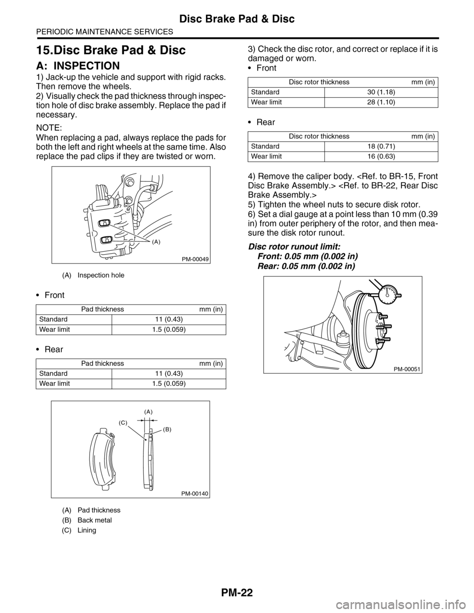
1) Jack-up the vehicle and support with rigid racks.
Then remove the wheels.
2) Visually check the pad thickness through inspec-
tion hole of disc brake assembly. Replace the pad if
necessary.
NOTE:
When replacing a pad, always replace the pads for
both the left and right wheels at the same time. Also
replace the pad clips if they are twisted or worn.
•Front
•Rear
3) Check the disc rotor, and correct or replace if it is
damaged or worn.
•Front
•Rear
4) Remove the caliper body.
5) Tighten the wheel nuts to secure disk rotor.
6) Set a dial gauge at a point less than 10 mm (0.39
in) from outer periphery of the rotor, and then mea-
sure the disk rotor runout.
Disc rotor runout limit:
Front: 0.05 mm (0.002 in)
Rear: 0.05 mm (0.002 in)
(A) Inspection hole
Pad thickness mm (in)
Standard 11 (0.43)
Wear limit 1.5 (0.059)
Pad thickness mm (in)
Standard 11 (0.43)
Wear limit 1.5 (0.059)
(A) Pad thickness
(B) Back metal
(C) Lining
PM-00049
(A)
PM-00140
(A)
(C)(B)
Disc rotor thickness mm (in)
Standard 30 (1.18)
Wear limit 28 (1.10)
Disc rotor thickness mm (in)
Standard 18 (0.71)
Wear limit 16 (0.63)
PM-00051
Page 2033 of 2453
5AT-17
General Description
AUTOMATIC TRANSMISSION
C: CAUTION
•Wear work clothing, including a cap, protective goggles and protective shoes during operation.
•Remove contamination including dirt and corrosion before removal, installation or disassembly.
•Keep the disassembled parts in order and protect them from dust and dirt.
•Until the oil pan is removed, do not place with the oil pan side facing up to prevent foreign matter from en-
tering the valve body.
•Before removal, installation or disassembly, be sure to clarify the failure. Avoid unnecessary removal, dis-
assembly and replacement.
•When disassembling the case and other light alloy parts, disassemble them by slightly tapping with a plas-
tic hammer. Do not pry apart with screwdrivers or other tools.
•Be careful not to burn yourself, because each part on the vehicle is hot after running.
•Use SUBARU genuine gear oil, grease or the equivalent. Do not mix them with that of another grade or
from other manufacturers.
•Be sure to tighten bolts and nuts to the specified torque.
•Place shop jacks or rigid racks at the specified points.
•Apply gear oil onto sliding or revolution surfaces before installation.
•Replace deformed or damaged snap rings with new parts.
•Before installing O-rings or oil seals, apply sufficient amount of ATF fluid to avoid damage and deforma-
tion.
•Be careful not to incorrectly install or fail to install O-rings, snap rings and other such parts.
•Before securing a part on a vise, place cushioning material such as wood blocks, aluminum plate, or cloth
between the part and the vise.
•Avoid damaging the mating surface of the case.
•Before applying liquid gasket, completely remove the old seal.
D: PREPARATION TOOL
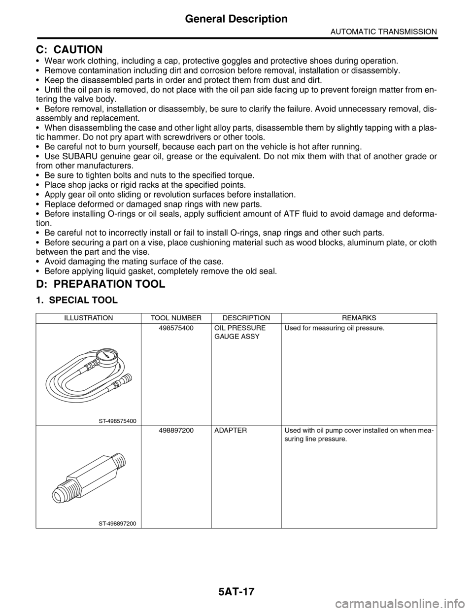
1. SPECIAL TOOL
ILLUSTRATION TOOL NUMBER DESCRIPTION REMARKS
498575400 OIL PRESSURE
GAUGE ASSY
Used for measuring oil pressure.
498897200 ADAPTER Used with oil pump cover installed on when mea-
suring line pressure.
ST-498575400
ST-498897200
Page 2256 of 2453
CS-4
General Description
CONTROL SYSTEMS
C: CAUTION
•Wear work clothing, including a cap, protective
goggles and protective shoes during operation.
•Remove contamination including dirt and corro-
sion before removal, installation or disassembly.
•Keep the disassembled parts in order and pro-
tect them from dust and dirt.
•Before removal, installation or disassembly, be
sure to clarify the failure. Avoid unnecessary re-
moval, installation, disassembly and replacement.
•Use SUBARU genuine fluid, grease etc. or
equivalent. Do not mix fluid, grease, etc. with that of
another grade or from other manufacturers.
•Be sure to tighten fasteners including bolts and
nuts to the specified torque.
•Place shop jacks or rigid racks at the specified
points.
•Apply grease onto sliding or revolution surfaces
before installation.
•Before installing O-rings or snap rings, apply suf-
ficient amount of fluid to avoid damage and defor-
mation.
•Before securing a part in a vise, place cushioning
material such as wood blocks, aluminum plate or
cloth between the part and the vise.
•Before disconnecting electrical connectors, be
sure to disconnect the negative terminal from bat-
tery.