2009 SUBARU TRIBECA jack point
[x] Cancel search: jack pointPage 1086 of 2453
VDC-5
General Description
VEHICLE DYNAMICS CONTROL (VDC)
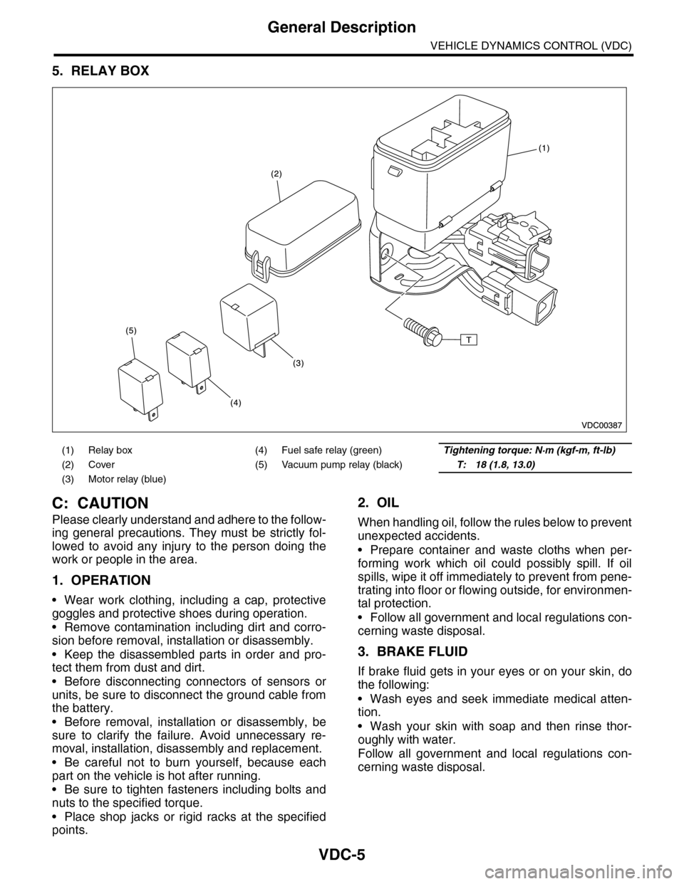
5. RELAY BOX
C: CAUTION
Please clearly understand and adhere to the follow-
ing general precautions. They must be strictly fol-
lowed to avoid any injury to the person doing the
work or people in the area.
1. OPERATION
•Wear work clothing, including a cap, protective
goggles and protective shoes during operation.
•Remove contamination including dirt and corro-
sion before removal, installation or disassembly.
•Keep the disassembled parts in order and pro-
tect them from dust and dirt.
•Before disconnecting connectors of sensors or
units, be sure to disconnect the ground cable from
the battery.
•Before removal, installation or disassembly, be
sure to clarify the failure. Avoid unnecessary re-
moval, installation, disassembly and replacement.
•Be careful not to burn yourself, because each
part on the vehicle is hot after running.
•Be sure to tighten fasteners including bolts and
nuts to the specified torque.
•Place shop jacks or rigid racks at the specified
points.
2. OIL
When handling oil, follow the rules below to prevent
unexpected accidents.
•Prepare container and waste cloths when per-
forming work which oil could possibly spill. If oil
spills, wipe it off immediately to prevent from pene-
trating into floor or flowing outside, for environmen-
tal protection.
•Follow all government and local regulations con-
cerning waste disposal.
3. BRAKE FLUID
If brake fluid gets in your eyes or on your skin, do
the following:
•Wash eyes and seek immediate medical atten-
tion.
•Wash your skin with soap and then rinse thor-
oughly with water.
Follow all government and local regulations con-
cerning waste disposal.
(1) Relay box (4) Fuel safe relay (green)Tightening torque: N·m (kgf-m, ft-lb)
(2) Cover (5) Vacuum pump relay (black)T: 18 (1.8, 13.0)
(3) Motor relay (blue)
Page 1113 of 2453
WT-7
Aluminum Wheel
WHEEL AND TIRE SYSTEM
3. Aluminum Wheel
A: REMOVAL
1) Apply the parking brake, and position select le-
ver to “P” or “LOW”.
2) Set the shop jacks or a lift to the specified points,
and support the vehicle with its wheels slightly con-
tacting the floor.
3) Loosen the wheel nuts.
4) Raise the vehicle until its wheels are off the
ground using the jack or a lift.
5) Remove the wheel nuts and wheels.
NOTE:
•When removing the wheels, be careful not to
damage the hub bolts.
•Place the wheels with their outer sides facing up-
ward to prevent wheels from being damaged.
B: INSTALLATION
1) Remove dirt from the mating surface of the
wheel and brake rotor.
2) Attach the wheel to the hub by aligning the wheel
bolt holes with the hub bolts.
3) Temporarily attach the wheel nuts to the hub
bolts. (In the case of aluminum wheels, use SUBA-
RU genuine wheel nuts for aluminum wheels.)
4) Tighten the nuts by hand, making sure the wheel
hub hole is aligned correctly to the guide portion of
hub.
5) Tighten the wheel nuts in a diagonal selection to
the specified torque. Use a wheel nut wrench.
Wheel nut tightening torque:
110 N·m (11.2 kgf-m, 81.1 ft-lb)
CAUTION:
•Tighten the wheel nuts in two or three steps
by gradually increasing the torque on opposing
nuts, until they reach the specified torque.
•Do not push the wrench by foot. Always use
both hands when tightening the nuts.
•Make sure the bolt, nut and the nut seating
surface of the wheel are free from oil.
6) If a wheel is removed for replacement or for re-
pair of a puncture, retighten the wheel nuts to the
specified torque after driving 1,000 km (600 miles).
C: INSPECTION
1) Deformation or damage to the rim may cause air
leakage. Check the rim flange for deformation,
cracks or damage, and repair or replace as neces-
sary.
2) Jack-up the vehicle until wheels clear the floor.
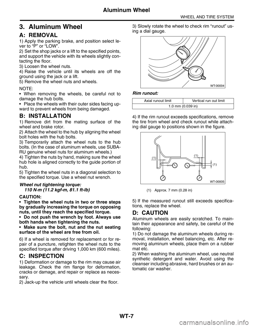
3) Slowly rotate the wheel to check rim “runout” us-
ing a dial gauge.
Rim runout:
4) If the rim runout exceeds specifications, remove
the tire from wheel and check runout while attach-
ing dial gauge to positions shown in the figure.
5) If the measured runout still exceeds specifica-
tions, replace the wheel.
D: CAUTION
Aluminum wheels are easily scratched. To main-
tain their appearance and safety, be careful of the
following:
1) Do not damage the aluminum wheels during re-
moval, installation, wheel balancing, etc. After re-
moving aluminum wheels, place them on a rubber
mat etc.
2) When washing the aluminum wheel, use neutral
synthetic detergent and water. Avoid using the
cleanser including abrasive, hard brushes or an au-
tomatic car washer.
Axial runout limit Vertical run out limit
1.0 mm (0.039 in)
(1) Approx. 7 mm (0.28 in)
WT-00004
WT-00005
(1)
(1)
(1)
Page 1125 of 2453
CO(H6DO)-6
General Description
COOLING
C: CAUTION
•Wear work clothing, including a cap, protective goggles and protective shoes during operation.
•Remove contamination including dirt and corrosion before removal, installation or disassembly.
•Keep the disassembled parts in order and protect them from dust and dirt.
•Before removal, installation or disassembly, be sure to clarify the failure. Avoid unnecessary removal, in-
stallation, disassembly and replacement.
•Be careful not to burn yourself, because each part on the vehicle is hot after running.
•Be sure to tighten fasteners including bolts and nuts to the specified torque.
•Place shop jacks or rigid racks at the specified points.
•Before disconnecting connectors of sensors or units, be sure to disconnect the ground cable from battery.
D: PREPARATION TOOL
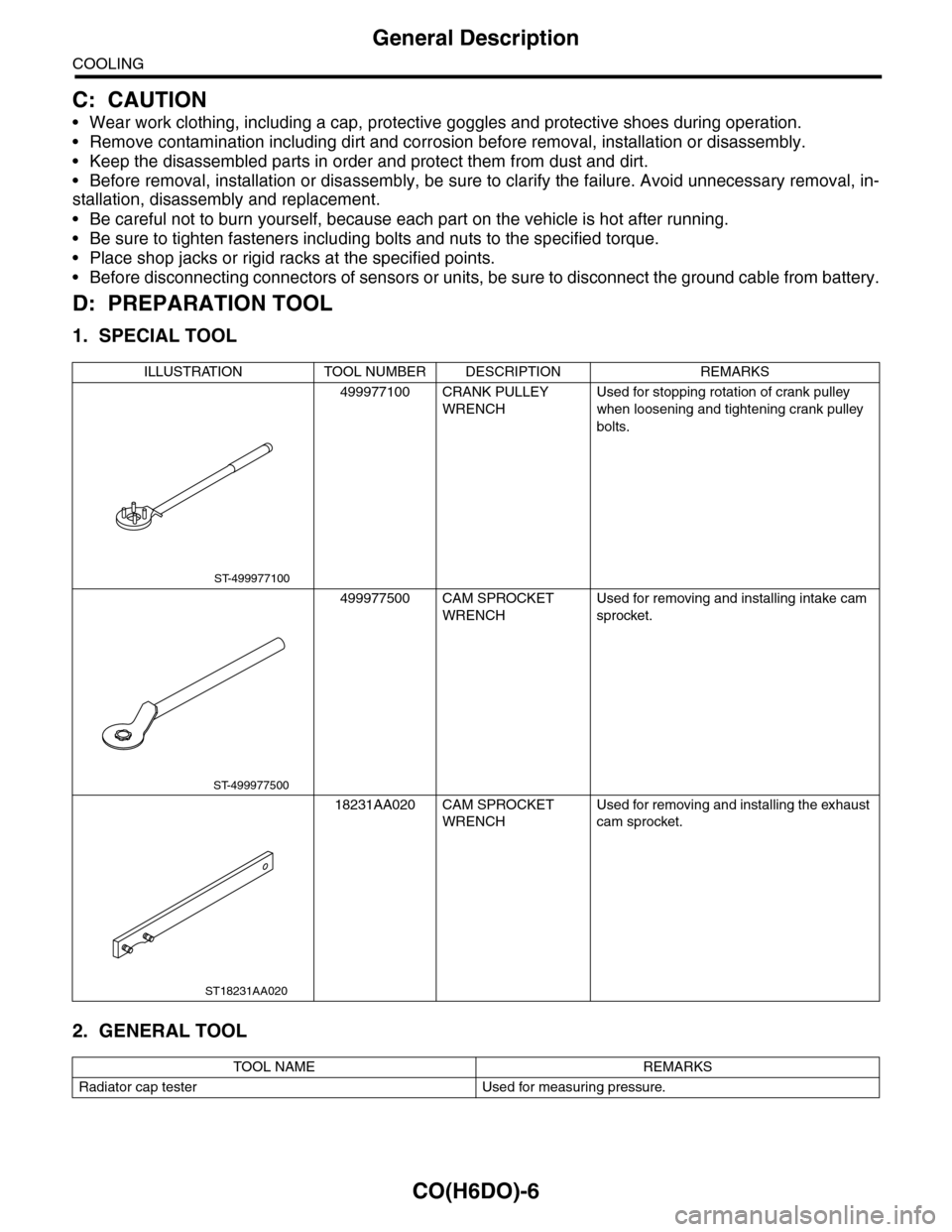
1. SPECIAL TOOL
2. GENERAL TOOL
ILLUSTRATION TOOL NUMBER DESCRIPTION REMARKS
499977100 CRANK PULLEY
WRENCH
Used for stopping rotation of crank pulley
when loosening and tightening crank pulley
bolts.
499977500 CAM SPROCKET
WRENCH
Used for removing and installing intake cam
sprocket.
18231AA020 CAM SPROCKET
WRENCH
Used for removing and installing the exhaust
cam sprocket.
TOOL NAME REMARKS
Radiator cap tester Used for measuring pressure.
ST-499977100
ST-499977500
ST18231AA020
Page 1150 of 2453
EC(H6DO)-2
General Description
EMISSION CONTROL (AUX. EMISSION CONTROL DEVICES)
1. General Description
A: CAUTION
•Wear work clothing, including a cap, protective
goggles and protective shoes during operation.
•Remove contamination including dirt and corro-
sion before removal, installation or disassembly.
•Keep the disassembled parts in order and pro-
tect them from dust and dirt.
•Before removal, installation or disassembly, be
sure to clarify the failure. Avoid unnecessary re-
moval, installation, disassembly and replacement.
•Be careful not to burn yourself, because each
part on the vehicle is hot after running.
•Be sure to tighten fasteners including bolts and
nuts to the specified torque.
•Place shop jacks or rigid racks at the specified
points.
•Before disconnecting connectors of sensors or
units, be sure to disconnect the ground cable from
the battery.
Page 1166 of 2453
EN(H6DO)(diag)-5
General Description
ENGINE (DIAGNOSTICS)
3. General Description
A: CAUTION
1) Airbag system wiring harness is routed near the
ECM, main relay and fuel pump relay.
CAUTION:
•All airbag system wiring harnesses and con-
nectors are colored yellow. Do not use electri-
cal test equipment on these circuits.
•Be careful not to damage the airbag system
wiring harness when servicing the ECM, TCM,
main relay and fuel pump relay.
2) Never connect the battery in reverse polarity.
•The ECM will be destroyed instantly.
•The fuel injector and other parts will be dam-
aged.
3) Do not disconnect the battery terminals while the
engine is running.
A large counter electromotive force will be generat-
ed in the generator, and this voltage may damage
electronic parts such as ECM etc.
4) Before disconnecting the connectors of each
sensor and ECM, be sure to turn the ignition switch
to OFF. Perform the clear memory mode after con-
necting the connectors.
5) Poor contact has been identified as a primary
cause of this problem. Measure the voltage or re-
sistance of individual sensor or all electrical control
modules using a tapered pin with a diameter of less
than 0.64 mm (0.025 in). Do not insert the pin more
than 5 mm (0.20 in) into the part.
6) Remove the ECM from the located position after
disconnecting two cables on battery.
Otherwise, the ECM may be damaged.
CAUTION:
When replacing the ECM, be careful not to use
the wrong spec. ECM to avoid any damage on
the fuel injection system.
7) Connectors of each sensor in the engine com-
partment and the harness connectors on the en-
gine side and body side are all designed to be
waterproof. Even if the connectors are waterproof,
take care not to allow water to get into them when
washing the vehicle, or when servicing the vehicle
in rainy weather.
8) Use ECM mounting stud bolts as the grounding
point to chassis when measuring voltage and resis-
tance in the passenger compartment.
9) Use the engine ground terminal or engine as-
sembly as the grounding point to chassis when
measuring the voltage and resistance in engine
compartment.
10) Every MFI-related part is a precision part. Do
not drop them.
11) Observe the following cautions when installing
a radio in MFI equipped models.
CAUTION:
•The antenna must be kept as far apart as pos-
sible from control unit. (The ECM is located un-
der the steering column, inside of the
instrument panel lower trim panel.)
•The antenna feeder must be placed as far apart
as possible from the ECM and MFI harness.
•Carefully adjust the antenna for correct
matching.
•When mounting a large power type radio, pay
special attention to the three items mentioned
above.
•Incorrect installation of the radio may affect
the operation of ECM.
12) Release the pressure in the fuel system before
disconnecting the fuel hose. If engine starts during
this operation, run it until it stops.
13) For the model with ABS, the ABS warning light
may illuminate when performing driving test with
jacked-up or lifted-up condition, but this is not a
system malfunction. The reason for this is the
speed difference between the front and rear
wheels. After diagnosis of engine control system,
perform the ABS memory clear procedure of self-
diagnosis function.
B: INSPECTION
Before performing diagnostics, check the following
item which might affect engine problems.
1. BATTERY
1) Measure the battery voltage and specific gravity
of electrolyte.
Standard voltage: 12 V
Specific gravity: Above 1.260
2) Check the condition of the main and other fuses,
and harnesses and connectors. Also check for
proper grounding.
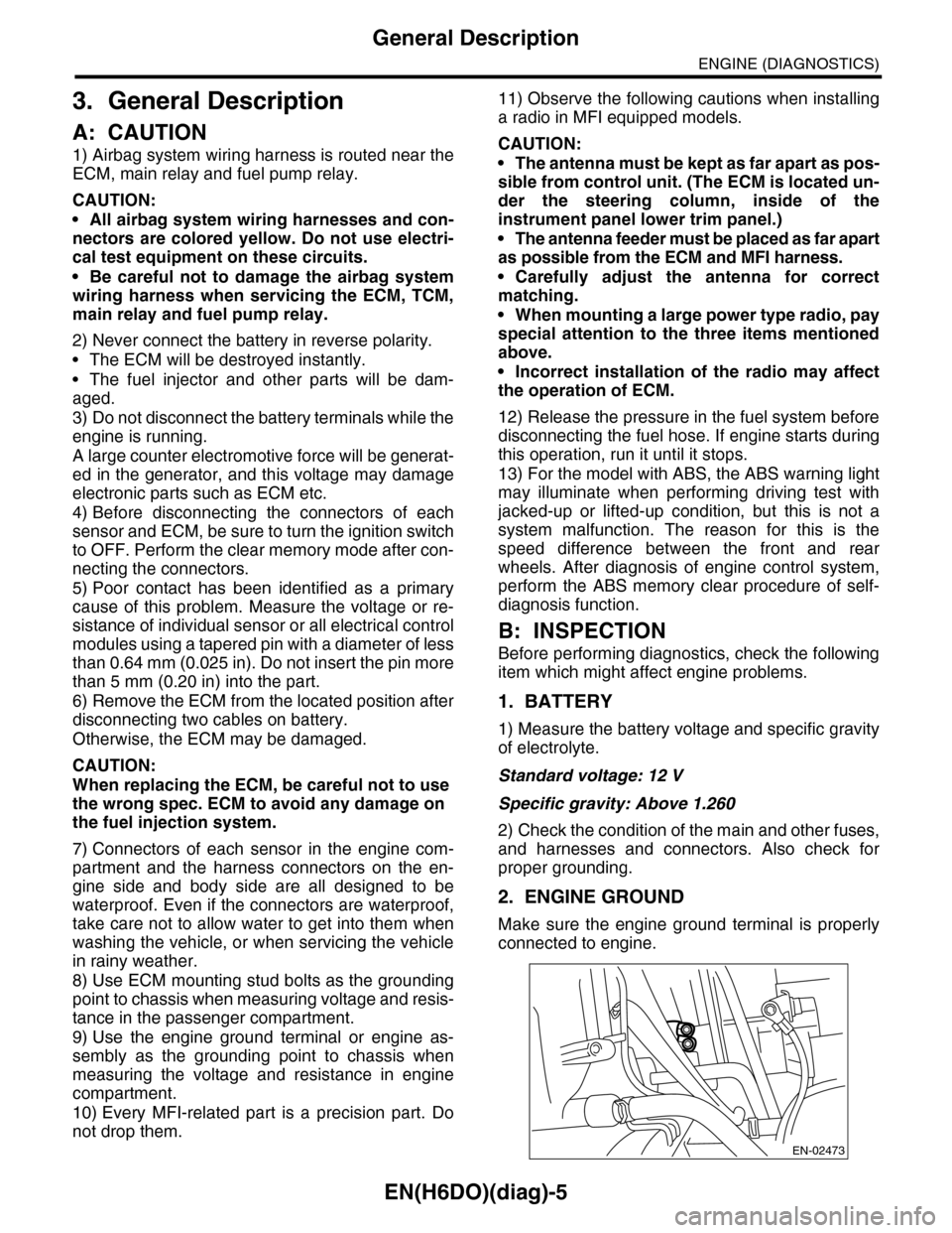
2. ENGINE GROUND
Make sure the engine ground terminal is properly
connected to engine.
EN-02473
Page 1557 of 2453
EX(H6DO)-3
General Description
EXHAUST
B: CAUTION
•Wear work clothing, including a cap, protective
goggles and protective shoes during operation.
•Remove contamination including dirt and corro-
sion before removal, installation or disassembly.
•Keep the disassembled parts in order and pro-
tect them from dust and dirt.
•Before removal, installation or disassembly, be
sure to clarify the failure. Avoid unnecessary re-
moval, installation, disassembly and replacement.
•Be careful not to burn yourself, because each
part on the vehicle is hot after running.
•Be sure to tighten fasteners including bolts and
nuts to the specified torque.
•Place shop jacks or rigid racks at the specified
points.
•Before disconnecting connectors of sensors or
units, be sure to disconnect the ground cable from
battery.
(1) Front catalytic converter upper
cover (RH)
(11) Front catalytic converter lower
cover (LH)
(23) Rear exhaust pipe
(24) Cushion rubber
(2) Front catalytic converter lower
cover (RH)
(12) Front exhaust pipe (LH) (25) Self-locking nut
(13) Front catalytic converter (LH) (26) Gasket
(3) Gasket (14) Front oxygen (A/F) sensor (LH)
(4) Front exhaust pipe (RH) (15) Rear oxygen sensor (LH)Tightening torque: N·m (kgf-m, ft-lb)
(5) Front catalytic converter (RH) (16) Muffler (RH)T1: 13 (1.3, 9.4)
(6) Front oxygen (A/F) sensor (RH) (17) Muffler (LH)T2: 18 (1.8, 13.0)
(7) Rear oxygen sensor (RH) (18) Rear catalytic converterT3: 21 (2.1, 15.2)
(8) Gasket (19) BracketT4: 30 (3.1, 22.4)
(9) Gasket (20) GasketT5: 35 (3.6, 26.0)
(10) Front catalytic converter upper
cover (LH)
(21) SpringT6: 48 (4.9, 35.4)
(22) Chamber
Page 1571 of 2453
FU(H6DO)-10
General Description
FUEL INJECTION (FUEL SYSTEMS)
C: CAUTION
•Wear work clothing, including a cap, protective goggles and protective shoes during operation.
•Remove contamination including dirt and corrosion before removal, installation or disassembly.
•Keep the disassembled parts in order and protect them from dust and dirt.
•Before removal, installation or disassembly, be sure to clarify the failure. Avoid unnecessary removal, in-
stallation, disassembly and replacement.
•Be careful not to burn yourself, because each part on the vehicle is hot after running.
•Be sure to tighten fasteners including bolts and nuts to the specified torque.
•Place shop jacks or rigid racks at the specified points.
•Before disconnecting connectors of sensors or units, be sure to disconnect the ground cable from the bat-
tery.
•Place “NO FIRE” signs near the working area.
•Be careful not to spill fuel on the floor.
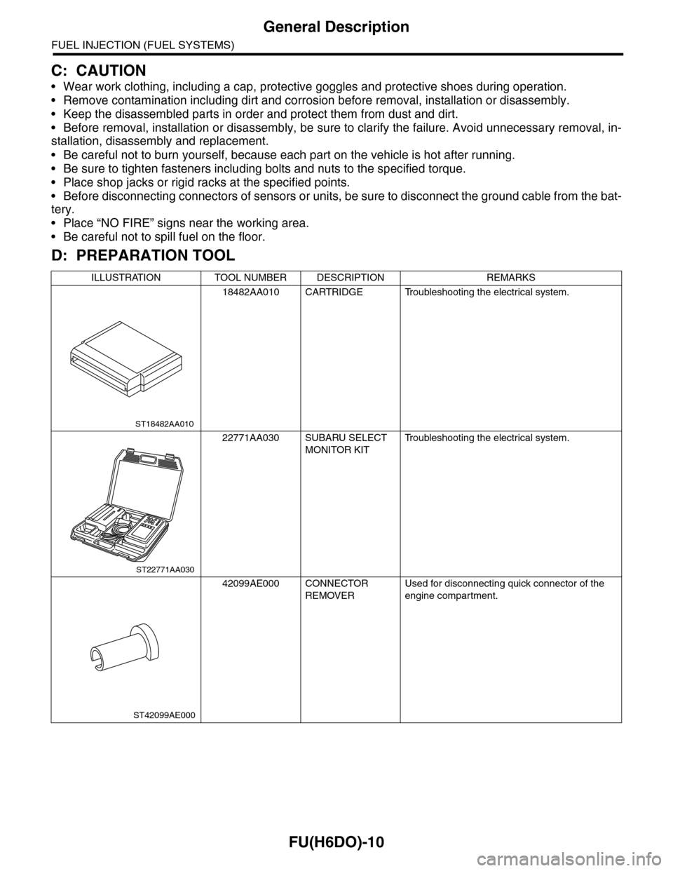
D: PREPARATION TOOL
ILLUSTRATION TOOL NUMBER DESCRIPTION REMARKS
18482AA010 CARTRIDGE Troubleshooting the electrical system.
22771AA030 SUBARU SELECT
MONITOR KIT
Tr o u b l e s h o o t i n g t h e e l e c t r i c a l s y s t e m .
42099AE000 CONNECTOR
REMOVER
Used for disconnecting quick connector of the
engine compartment.
ST18482AA010
ST22771AA030
ST42099AE000
Page 1838 of 2453
IG(H6DO)-3
General Description
IGNITION
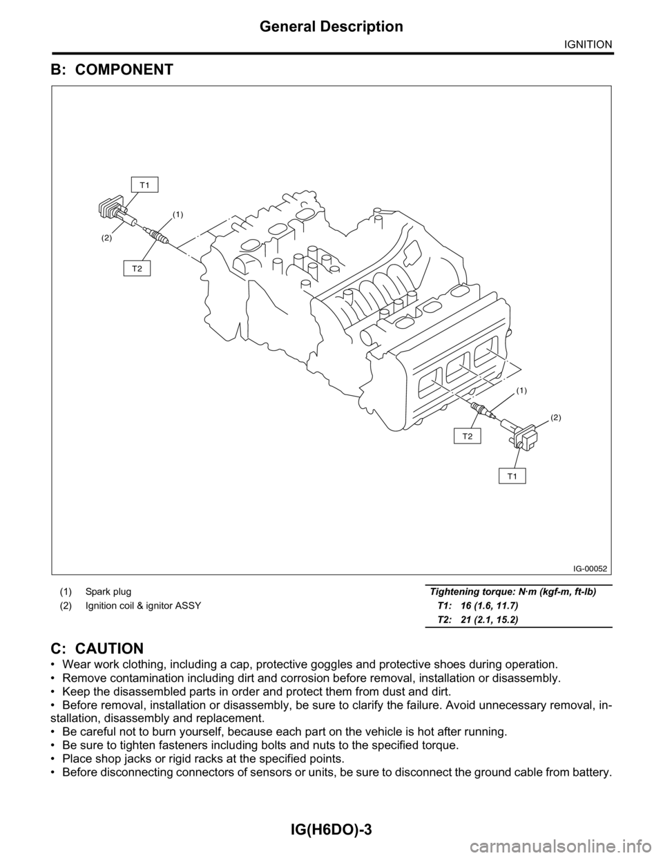
B: COMPONENT
C: CAUTION
•Wear work clothing, including a cap, protective goggles and protective shoes during operation.
•Remove contamination including dirt and corrosion before removal, installation or disassembly.
•Keep the disassembled parts in order and protect them from dust and dirt.
•Before removal, installation or disassembly, be sure to clarify the failure. Avoid unnecessary removal, in-
stallation, disassembly and replacement.
•Be careful not to burn yourself, because each part on the vehicle is hot after running.
•Be sure to tighten fasteners including bolts and nuts to the specified torque.
•Place shop jacks or rigid racks at the specified points.
•Before disconnecting connectors of sensors or units, be sure to disconnect the ground cable from battery.
(1) Spark plug Tightening torque: N·m (kgf-m, ft-lb)
(2) Ignition coil & ignitor ASSY T1: 16 (1.6, 11.7)
T2: 21 (2.1, 15.2)
IG-00052
(1)
(1)
(2)
(2)
T1
T2
T2
T1