2009 SUBARU TRIBECA check oil
[x] Cancel search: check oilPage 727 of 2453

BR-13
Front Brake Pad
BRAKE
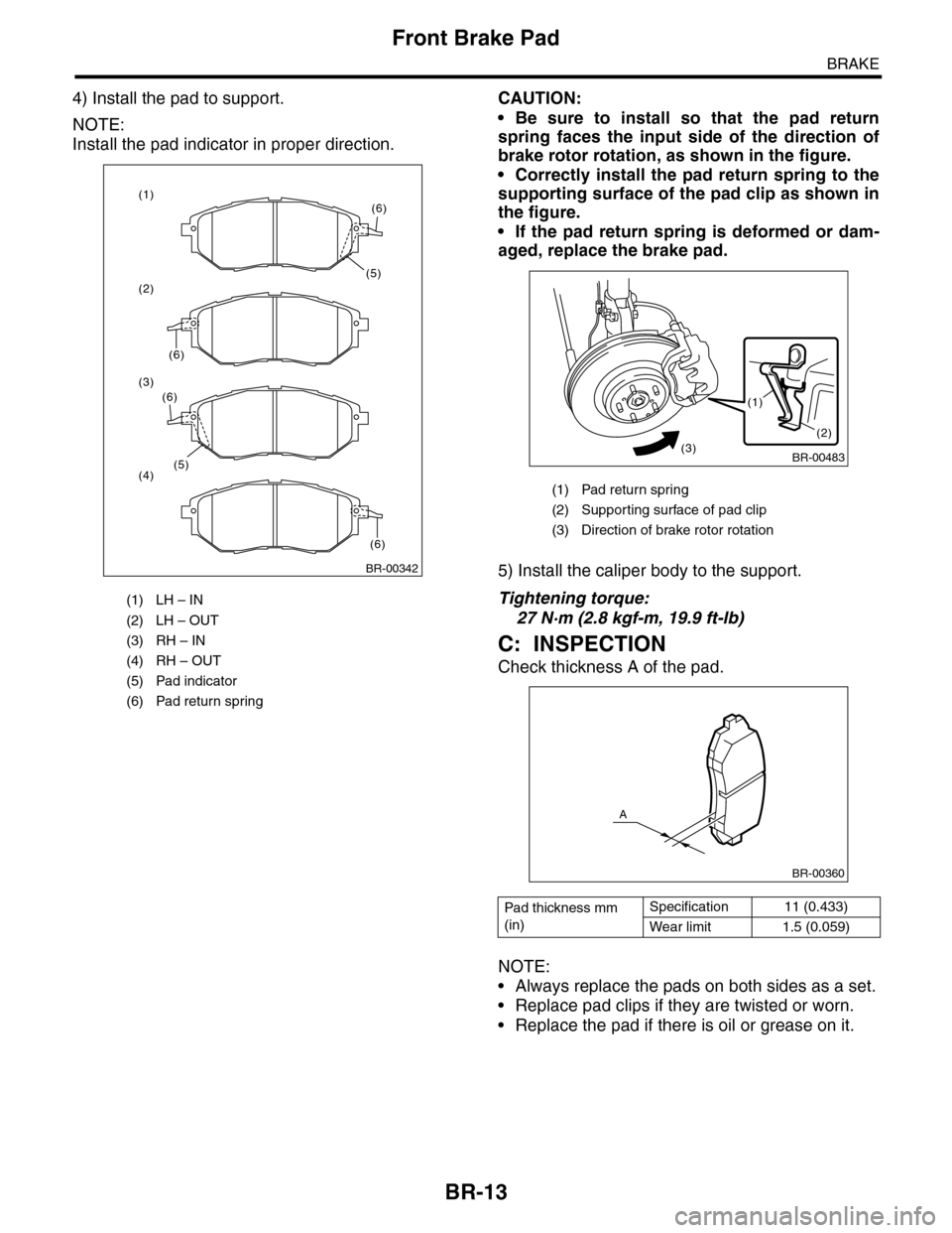
4) Install the pad to support.
NOTE:
Install the pad indicator in proper direction.
CAUTION:
•Be sure to install so that the pad return
spring faces the input side of the direction of
brake rotor rotation, as shown in the figure.
•Correctly install the pad return spring to the
supporting surface of the pad clip as shown in
the figure.
•If the pad return spring is deformed or dam-
aged, replace the brake pad.
5) Install the caliper body to the support.
Tightening torque:
27 N·m (2.8 kgf-m, 19.9 ft-lb)
C: INSPECTION
Check thickness A of the pad.
NOTE:
•Always replace the pads on both sides as a set.
•Replace pad clips if they are twisted or worn.
•Replace the pad if there is oil or grease on it.
(1) LH – IN
(2) LH – OUT
(3) RH – IN
(4) RH – OUT
(5) Pad indicator
(6) Pad return spring
BR-00342
(5)
(6)
(6)
(1)
(2)
(3)
(4)(5)
(6)
(6)
(1) Pad return spring
(2) Suppor ting surface of pad clip
(3) Direction of brake rotor rotation
Pad thickness mm
(in)
Specification 11 (0.433)
Wear limit 1.5 (0.059)
BR-00483
(1)
(2)(3)
BR-00360
A
Page 733 of 2453

BR-19
Rear Brake Pad
BRAKE
5. Rear Brake Pad
A: REMOVAL
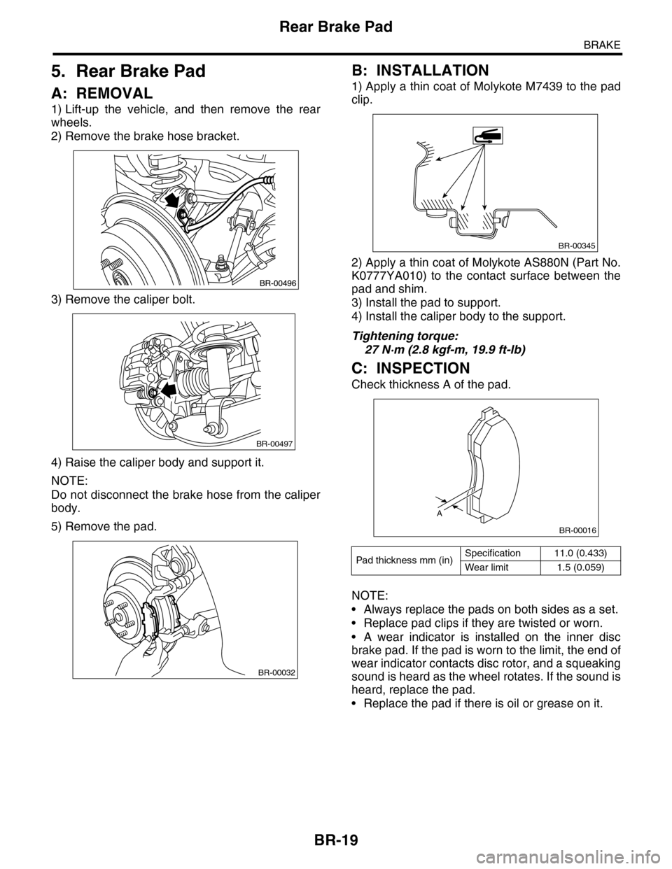
1) Lift-up the vehicle, and then remove the rear
wheels.
2) Remove the brake hose bracket.
3) Remove the caliper bolt.
4) Raise the caliper body and support it.
NOTE:
Do not disconnect the brake hose from the caliper
body.
5) Remove the pad.
B: INSTALLATION
1) Apply a thin coat of Molykote M7439 to the pad
clip.
2) Apply a thin coat of Molykote AS880N (Part No.
K0777YA010) to the contact surface between the
pad and shim.
3) Install the pad to support.
4) Install the caliper body to the support.
Tightening torque:
27 N·m (2.8 kgf-m, 19.9 ft-lb)
C: INSPECTION
Check thickness A of the pad.
NOTE:
•Always replace the pads on both sides as a set.
•Replace pad clips if they are twisted or worn.
•A wear indicator is installed on the inner disc
brake pad. If the pad is worn to the limit, the end of
wear indicator contacts disc rotor, and a squeaking
sound is heard as the wheel rotates. If the sound is
heard, replace the pad.
•Replace the pad if there is oil or grease on it.
BR-00497
BR-00032
Pad thickness mm (in)Specification 11.0 (0.433)
Wear limit 1.5 (0.059)
BR-00345
A
BR-00016
Page 757 of 2453

BVC(diag)-2
Basic Diagnostic Procedure
BRAKE VACUUM CONTROL (BVC) (DIAGNOSTICS)
1. Basic Diagnostic Procedure
A: PROCEDURE
CAUTION:
•Subaru Select Monitor is required for reading DTC, reading the current data and clearing the mem-
ory.
•Remove foreign matter (dust, water, oil, etc.) from the engine control module (ECM) connector
when removing or installing.
NOTE:
•To check the harness for broken wires or short circuits, shake problem spot or connector.
•Refer to “Check List for Interview”.
Step Check Yes No
1CHECK PRE-INSPECTION.
1) Ask the customer when and how the trou-
ble occurred using interview check list.
2) Check the error display. (Odo/trip meter)
Is “Er-bb” displayed on the
screen?
Go to step 3.Go to step 2.
2BASIC INSPECTION
Check the components which might affect the
brake vacuum control.
Is the component that might
affect the vacuum control nor-
mal?
Go to step 3.Repair or replace
each component.
3CHECK INDICATION OF DTC.
1) Turn the ignition switch to OFF.
2) Connect the Subaru Select Monitor to data
link connector.
3) Turn the ignition switch to ON, and the Sub-
aru Select Monitor power switch to ON.
4) Read the DTC.
(DTC).>
5) Record all DTC.
Is DTC displayed? Go to step 5.Go to step 4.
4PERFORM GENERAL DIAGNOSTICS.
Inspect using “General Diagnostic Table”.
Is result of inspection OK? Finish the diagno-
sis.
Go to step 5.
5PERFORM THE DIAGNOSIS.
1) Correct the cause of trouble according to
DTC.
2) Perform the clear memory mode.
Mode.>
3) Perform the inspection mode.
Mode.>
4) Read the DTC.
(DTC).>
Is DTC displayed? Repeat step 4 until
DTC is not shown.
Finish the diagno-
sis.
Page 796 of 2453

DI-12
Differential Gear Oil
DIFFERENTIALS
2. Differential Gear Oil
A: INSPECTION
1) Remove the filler plug, and then check the gear
oil. Replace the gear oil if it is contaminated or de-
teriorated.
2) Check that the gear oil level is up to the bottom
of the filler plug hole. If the level is low, refill up to
the bottom of filler plug.
B: REPLACEMENT
1) Jack–up the vehicle and support it with rigid
racks.
2) Remove the oil drain plug and filler plug, and
drain the gear oil.
CAUTION:
Be careful not to burn your hands, because
gear oil becomes extremely hot after running.
3) Tighten the oil drain plug.
NOTE:
Use a new metal gasket.
Tightening torque:
29 N·m (3.0 kgf-m, 21.7 ft-lb)
4) Fill the differential carrier with gear oil to the bot-
tom of filler plug.
NOTE:
Carefully refill oil while watching the level. Exces-
sive or insufficient oil must be avoided.
Recommended gear oil:
Oil capacity:
0.8 2(0.8 US qt, 0.7 Imp qt)
5) Install the filler plug.
NOTE:
Use a new metal gasket.
Tightening torque:
29 N·m (3.0 kgf-m, 21.7 ft-lb)
(A) Filler plug
(B) Drain plug
(A) Filler plug
(B) Drain plug
(B)DI-00355
(A)
(A)
DI-00357
(B)
(A) Filler plug
(B) Drain plug
(B)DI-00355
(A)
Page 803 of 2453

DI-19
Rear Differential (VA–type)
DIFFERENTIALS
14) Extract the companion flange with a puller.
15) Removes the drive pinion shaft.
16) Remove the rear bearing cone from drive pin-
ion by supporting the cone with ST.
NOTE:
Place the replacer so that its center-recessed side
faces the pinion gear.
ST 398517700 REPLACER
17) Remove the front oil seal from differential carri-
er using screwdriver.
18) Remove the pilot bearing, front bearing cone
and collar.
19) When replacing the bearings, hit out the front
bearing cup and rear bearing cup in this order out of
case using a brass bar.
D: ASSEMBLY
NOTE:
•Assemble in the reverse order of disassembly.
•Check and adjust each part during assembly.
•Use a new gasket.
•Keep the shims and washers in order, so that
they are not improperly installed.
•Thoroughly clean the surfaces on which the
shims, washers and bearings are to be installed.
•Apply gear oil when installing the bearings and
thrust washers.
•Be careful not to mix up the RH and LH bearing
races.
•Replace the oil seal with a new one at every dis-
assembly. Apply grease to the lips when installing
the oil seal.
•Be careful not to mix up the differential oil seal
RH and LH.
(A) Companion flange
(B) Puller
(A) Pilot bearing
(B) Collar
(C) Front bearing
(D) Rear bearing cup
(B)
(A)
DI-00394
DI-00373
ST
(B)(A)(C)(D)
DI-00374
(A) 2 cutout portions along diagonal lines
(B) Tap alternately with brass bar.
(B)
(A)
DI-00077
DI-00078
Page 811 of 2453

DI-27
Rear Differential (VA–type)
DIFFERENTIALS
•Flank contact
Check item: Backlash is too small.
Contact pattern
Corrective action: Reduce the thickness of pinion
height adjusting washer according to the procedure for
bringing drive pinion away from hypoid driven gear.
•Toe contact (inner side contact)
Check item: Teeth contact area is too small.
Contact pattern
Corrective action: Reduce the thickness of pinion
height adjusting washer according to the procedure
for bringing drive pinion away from hypoid driven gear.
•Heel contact (outside end contact)
Check item: Teeth contact area is too small.
Contact pattern
Corrective action: Increase thickness of drive pin-
ion height adjusting washer in order to bring drive
pinion close to hypoid driven gear.
20) If proper tooth contact is not obtained, once
again adjust the drive pinion height and the differ-
ential side bearing preload (already mentioned)
and the hypoid gear backlash.
21) Attach a new gasket, rear cover, and ground
stay to the differential carrier.
Tightening torque:
34 N·m (3.5 kgf-m, 25.1 ft-lb)
22) Using new gaskets, install the rear differential
oil temperature switch.
Tightening torque:
60 N·m (6.1 kgf-m, 44.3 ft-lb)
AT-00209
AT-00213
AT-00210
AT-00213
AT-00211
AT-00212
DI-00477
Page 812 of 2453

DI-28
Rear Differential (VA–type)
DIFFERENTIALS
23) Affix with the attachment clip so that the white
marking of the hose is within the range of Z (87°).
E: INSPECTION
Wash all the disassembled parts clean, and exam-
ine them for wear, damage or other defects. Repair
or replace the defective parts as necessary.
1) Hypoid driven gear and drive pinion
•If there is evidently an abnormal tooth contact,
find out the cause and adjust until the teeth contact
correctly. Replace the gear if there is an excessive
worn or an incapable adjustment.
•If crack, cutout or seizure is found, replace the
parts as a set. Slight damage of some teeth can be
corrected by oil stone or the like.
2) Side gear and pinion mate gear
•Replace the differential case assembly if cracks,
scoring or other defects are evident on tooth sur-
face.
3) Bearing
Replace if seizure, peeling, wear, rust, dragging
during rotation, noise or other defect is evident.
4) Oil seal
Replace if deformed or damaged, and at every dis-
assembling.
5) Differential carrier
Replace if the bearing bores are worn or damaged.
6) Differential case
Replace if its sliding surfaces are worn or cracked.
7) Companion flange
Replace if the oil seal lip contact surface shows
cracking.
1. HYPOID DRIVEN GEAR BACKLASH
Using a dial gauge, check the backlash of hypoid
driven gear.
Hypoid driven gear backlash:
0.10 — 0.15 mm (0.0039 — 0.0059 in)
If the hypoid driven gear backlash is not within the
specification, adjust the side bearing preload or re-
pair if necessary.
2. TOOTH CONTACT BETWEEN HYPOID
DRIVEN GEAR AND DRIVE PINION
Inspect the tooth contact between the hypoid driv-
en gear and drive pinion.
3. COMPANION FLANGE
1) If rust or dirt is attached to the companion flange,
remove them.
2) Set a dial gauge at a companion flange surface
(mating surface of propeller shaft and companion
flange), and then measure the companion flange
runout.
Limit of runout:
0.08 mm (0.003 in)
(1) 0 — 1 mm (0 — 0.04 in)
(2) Marking
DI-00478
B
B
A
A
Z
(1)
(2)
DI-00099
DI-00360
Page 813 of 2453

DI-29
Rear Differential (VA–type)
DIFFERENTIALS
3) Set the gauge inside of the companion flange,
and measure the runout.
Limit of runout:
0.08 mm (0.003 in)
4) If either runout exceeds the limit, move the
phase of companion flange and drive pinion 90°
each, and find the point where the runout will be
within the limit.
5) If the runout exceeds the limit when changing
the phase, replace the companion flange and re-
check the runout.
6) If the runout exceeds the limit after replacing the
companion flange, the drive pinion may be assem-
bled incorrectly or bearing is faulty.
4. REAR DIFFERENTIAL OIL TEMPERA-
TURE SWITCH
Inspect the continuity of the rear differential oil tem-
perature switch.
F: ADJUSTMENT
1. HYPOID DRIVEN GEAR BACKLASH
Adjust hypoid driven gear backlash.
2. TOOTH CONTACT BETWEEN HYPOID
DRIVEN GEAR AND DRIVE PINION
Adjust the tooth contact between hypoid driven
gear and drive pinion gear.
Specified resistance Criteria
Less than 1 ΩNormal
1 MΩ or more Replacement
DI-00361
DI-00479