Page 1142 of 2453
CO(H6DO)-23
Radiator Main Fan and Fan Motor
COOLING
4) Install the radiator stay.
(1) Install the latch.
Tightening torque:
33 N·m (3.4 kgf-m, 25 ft-lb)
(2) Connect the radiator hose brackets.
(3) Hold the harness to the radiator stay with a
clip.
(4) Tighten the bolts on the left side of the radi-
ator stay.
Tightening torque:
18 N·m (1.8 kgf-m, 13.3 ft-lb)
(5) Tighten the bolts on the right side of the ra-
diator stay.
Tightening torque:
18 N·m (1.8 kgf-m, 13.3 ft-lb)
5) Install the radiator upper brackets.
Tightening torque:
12 N·m (1.2 kgf-m, 8.9 ft-lb)
6) Install the front upper cover.
7) Install the air intake duct.
INSTALLATION, Air Intake Duct.>
8) Lift-up the vehicle.
CO-02179
CO-02180
CO-02181
CO-02177
CO-02176
Page 1145 of 2453
CO(H6DO)-26
Reservoir Tank
COOLING
10.Reservoir Tank
A: REMOVAL
1) Set the vehicle on a lift.
2) Remove the collector cover.
3) Lift-up the vehicle.
4) Remove the under cover.
5) Remove the bolts on the underside of the radia-
tor stay.
6) Lower the vehicle.
7) Remove the air intake duct.
7, REMOVAL, Air Intake Duct.>
8) Remove the front upper cover.
9) Remove the radiator upper brackets.
10) Remove the radiator stay.
(1) Remove the latch.
(2) Remove the radiator hose bracket.
(3) Remove the clip holding the harness.
(4) Remove the bolts on the left side of the radi-
ator stay.
(5) Remove the bolts on the right side of the ra-
diator stay.
CO-02175
CO-02176
CO-02177
CO-02179
CO-02180
CO-02181
Page 1147 of 2453
CO(H6DO)-28
Reservoir Tank
COOLING
3) Install the radiator upper brackets.
Tightening torque:
12 N·m (1.2 kgf-m, 8.9 ft-lb)
4) Install the front upper cover.
5) Install the air intake duct.
INSTALLATION, Air Intake Duct.>
6) Lift-up the vehicle.
7) Tighten the bolts on the lower side of the radiator
stay.
Tightening torque:
18 N·m (1.8 kgf-m, 13.3 ft-lb)
8) Install the under cover.
9) Lower the vehicle.
10) Install the collector cover.
C: INSPECTION
Make sure the engine coolant level is between
“FULL” and “LOW”.
CO-02177
CO-02176
CO-02175
Page 1148 of 2453
CO(H6DO)-29
Radiator Fan Control Unit
COOLING
11.Radiator Fan Control Unit
A: REMOVAL
1) Disconnect the ground cable from battery.
2) Remove the air intake duct.
7, REMOVAL, Air Intake Duct.>
3) Remove the front upper cover.
4) Remove the radiator fan control unit.
(1) Disconnect the connector from radiator fan
control unit.
(2) Remove the screws which hold the radiator
fan control unit.
B: INSTALLATION
Install in the reverse order of removal.
Tightening torque:
2.6 N·m (0.27 kgf-m, 1.9 ft-lb)
(A) Connector
(B) Screw
CO-02176
CO-02204
(A)
(B)
Page 1154 of 2453
EC(H6DO)-6
Purge Control Solenoid Valve
EMISSION CONTROL (AUX. EMISSION CONTROL DEVICES)
5. Purge Control Solenoid Valve
A: REMOVAL
1) Remove the collector cover.
2) Disconnect the ground cable from battery.
3) Remove the air intake chamber.
ber.>
4) Disconnect the connector and hoses of purge
control solenoid valve, and then remove the purge
control solenoid valve.
B: INSTALLATION
Install in the reverse order of removal.
Tightening torque:
19 N·m (1.9 kgf-m, 14.0 ft-lb)
NOTE:
Connect the evaporation hose as shown in the fig-
ure.
C: INSPECTION
Make sure the hoses are not cracked or loose.
(A) To fuel pipe (evaporation line)
(B) To intake manifold
EC-02019
EC-02019
EC-02020
(B)
(A)
Page 1167 of 2453

EN(H6DO)(diag)-6
General Description
ENGINE (DIAGNOSTICS)
C: NOTE
1. GENERAL DESCRIPTION
•The on-board diagnostics (OBD) system detects
and indicates a fault in various inputs and outputs
of the complex electronic control. Malfunction indi-
cator light in the combination meter indicates oc-
currence of a fault or trouble.
•Further, against such a failure or sensors as may
disable the drive, the fail-safe function is provided
to ensure the minimal drivability.
•The OBD system incorporated with the vehicles
within this engine family complies with OBD-II Reg-
ulations. The OBD system monitors the compo-
nents and the system malfunction listed in Engine
Section which affects on emissions.
•When the system decides that a malfunction oc-
curs, malfunction indicator light illuminates. At the
same time of the malfunction indicator light illumi-
nation or blinking, a DTC and a freeze frame en-
gine conditions are stored into on-board computer.
•The OBD system stores freeze frame engine
condition data (engine load, engine coolant tem-
perature, fuel trim, engine speed and vehicle
speed, etc.) into on-board computer when it detects
a malfunction first.
•If the OBD system detects the various malfunc-
tions including the fault of fuel trim or misfire, the
OBD system first stores freeze frame engine condi-
tions about fuel trim or misfire.
•When the malfunction does not occur again for
three consecutive driving cycles, malfunction indi-
cator light is turned off, but DTC remains at on-
board computer.
•When troubleshooting the vehicle which com-
plies with OBD-II Regulations, connect the Subaru
Select Monitor or general scan tool to the vehicle.
2. ENGINE AND EMISSION CONTROL SYS-
TEM
•The Multipoint Fuel Injection (MFI) system is a
system that supplies the optimum air-fuel mixture
to the engine for all the various operating condi-
tions through the use of the latest electronic tech-
nology.
With this system fuel, which is pressurized at a con-
stant pressure, is injected into the intake air pas-
sage of the cylinder head. The injection quantity of
fuel is controlled by an intermittent injection system
where the electro-magnetic injection valve (fuel in-
jector) opens only for a short period of time, de-
pending on the quantity of air required for one cycle
of operation. In actual operation, the injection quan-
tity is determined by the duration of an electric
pulse applied to the fuel injector and this permits
simple, yet highly precise metering of the fuel.
•Further, all the operating conditions of the engine
are converted into electric signals, and this results
in additional features of the system, such as large
improved adaptability, easier addition of compen-
sating element etc.
The MFI system also has the following features:
•Reduced emission of harmful exhaust gases.
•Reduced in fuel consumption.
•Increased engine output.
•Superior acceleration and deceleration.
•Superior startability and warm-up perfor-
mance in cold weather since compensation is
made for coolant and intake air temperature.
Page 1170 of 2453
EN(H6DO)(diag)-9
Electrical Component Location
ENGINE (DIAGNOSTICS)
•Sensor
(1) Mass air flow and intake air tem-
perature sensor
(3) Engine coolant temperature sen-
sor
(6) Camshaft position sensor
(7) Crankshaft position sensor
(2) Manifold absolute pressure sensor (4) Electronic throttle control (8) Oil temperature sensor
(5) Knock sensor
EN-03684
(6)(6) (8)
(3)(2)
(7)
(1)
(4) (5)(5)
Page 1179 of 2453

EN(H6DO)(diag)-18
Engine Control Module (ECM) I/O Signal
ENGINE (DIAGNOSTICS)
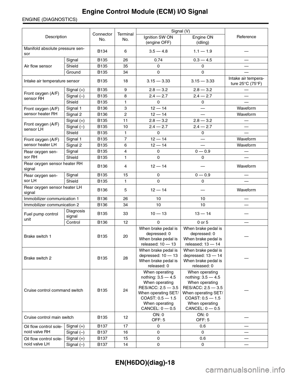
Manifold absolute pressure sen-
sorB134 6 3.5 — 4.8 1.1 — 1.9 —
Air flow sensor
Signal B135 26 0.74 0.3 — 4.5 —
Shield B135 35 0 0 —
Ground B135 34 0 0 —
Intake air temperature sensor B135 18 3.15 — 3.33 3.15 — 3.33Intake air tempera-
ture 25°C (75°F)
Fr o nt ox yg e n ( A / F)
sensor RH
Signal (+) B135 9 2.8 — 3.2 2.8 — 3.2 —
Signal (–) B135 8 2.4 — 2.7 2.4 — 2.7 —
Shield B135 1 0 0 —
Fr o nt ox yg e n ( A / F)
sensor heater RH
Signal 1 B136 3 12 — 14 — Waveform
Signal 2 B136 2 12 — 14 — Waveform
Fr o nt ox yg e n ( A / F)
sensor LH
Signal (+) B135 11 2.8 — 3.2 2.8 — 3.2 —
Signal (–) B135 10 2.4 — 2.7 2.4 — 2.7 —
Shield B135 1 0 0 —
Fr o nt ox yg e n ( A / F)
sensor heater LH
Signal 1 B135 7 12 — 14 — Waveform
Signal 2 B135 6 12 — 14 — Waveform
Rear oxygen sen-
sor RH
Signal B135 4 0 0 — 0.9 —
Shield B135 1 0 0 —
Rear oxygen sensor heater RH
signalB136 4 12 — 14 — Waveform
Rear oxygen sen-
sor LH
Signal B135 15 0 0 — 0.9 —
Shield B135 1 0 0 —
Rear oxygen sensor heater LH
signalB136 5 12 — 14 — Waveform
Immobilizer communication 1 B136 26 10 10 —
Immobilizer communication 2 B136 34 10 10 —
Fuel pump control
unit
Diagnosis
signalB135 33 10 — 13 13 — 14 —
Control B136 12 0 0 or 5 —
Brake switch 1 B135 20
When brake pedal is
depressed: 0
When brake pedal is
released: 10 — 13
When brake pedal is
depressed: 0
When brake pedal is
released: 13 — 14
—
Brake switch 2 B135 28
When brake pedal is
depressed: 10 — 13
When brake pedal is
released: 0
When brake pedal is
depressed: 13 — 14
When brake pedal is
released: 0
—
Cruise control command switch B135 24
When operating
nothing: 3.5 — 4.5
When operating
RES/ACC: 2.5 — 3.5
When operating SET/
COAST: 0.5 — 1.5
When operating
CANCEL: 0 — 0.5
When operating
nothing: 3.5 — 4.5
When operating
RES/ACC: 2.5 — 3.5
When operating SET/
COAST: 0.5 — 1.5
When operating
CANCEL: 0 — 0.5
—
Cruise control main switch B135 12ON: 0
OFF: 5
ON: 0
OFF: 5—
Oil flow control sole-
noid valve RH
Signal (+) B137 17 0 0.6 —
Signal (–) B137 16 0 0 —
Oil flow control sole-
noid valve LH
Signal (+) B137 15 0 0.6 —
Signal (–) B137 14 0 0 —
DescriptionConnector
No.
Te r m i n a l
No.
Signal (V)
ReferenceIgnition SW ON
(engine OFF)
Engine ON
(idling)