Page 917 of 2453
PS-37
Pipe Assembly
POWER ASSISTED SYSTEM (POWER STEERING)
6. Pipe Assembly
A: REMOVAL
1) Disconnect the ground cable from the battery.
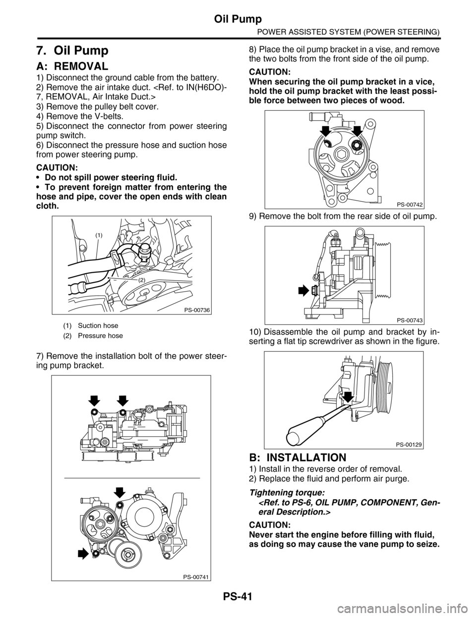
2) Lift-up the vehicle, and then remove the front
crossmember support plate and jack-up plate.
3) Remove the one pipe joint at the center of the
gearbox, and connect the vinyl hose to the pipe and
the joint. Discharge the fluid by turning the steering
wheel fully clockwise and counterclockwise. Dis-
charge the fluid similarly from other pipes.
4) Remove the clamp E from return hose and pres-
sure hose.
5) Disconnect the pipe D from return hose and pipe
C from pressure hose.
6) Remove the air intake duct.
7, REMOVAL, Air Intake Duct.>
(1) Front crossmember support plate
(2) Jack–up plate
(1) Pipe A
(2) Pipe B
(2)(1)
(1)
FS-00200
(2)
PS-00553
(1)
(1) Return hose
(2) Pressure hose
(3) Clamp E
(1) Pipe C
(2) Pipe D
(3) Pressure hose
(4) Return hose
PS-00537
(3)
(1)
(2)
PS-00538
(4)
(3)
(2)
(1)
Page 921 of 2453

PS-41
Oil Pump
POWER ASSISTED SYSTEM (POWER STEERING)
7. Oil Pump
A: REMOVAL
1) Disconnect the ground cable from the battery.
2) Remove the air intake duct.
7, REMOVAL, Air Intake Duct.>
3) Remove the pulley belt cover.
4) Remove the V-belts.
5) Disconnect the connector from power steering
pump switch.
6) Disconnect the pressure hose and suction hose
from power steering pump.
CAUTION:
•Do not spill power steering fluid.
•To prevent foreign matter from entering the
hose and pipe, cover the open ends with clean
cloth.
7) Remove the installation bolt of the power steer-
ing pump bracket.
8) Place the oil pump bracket in a vise, and remove
the two bolts from the front side of the oil pump.
CAUTION:
When securing the oil pump bracket in a vice,
hold the oil pump bracket with the least possi-
ble force between two pieces of wood.
9) Remove the bolt from the rear side of oil pump.
10) Disassemble the oil pump and bracket by in-
serting a flat tip screwdriver as shown in the figure.
B: INSTALLATION
1) Install in the reverse order of removal.
2) Replace the fluid and perform air purge.
Tightening torque:
eral Description.>
CAUTION:
Never start the engine before filling with fluid,
as doing so may cause the vane pump to seize.
(1) Suction hose
(2) Pressure hose
PS-00736
(1)
(2)
PS-00741
PS-00742
PS-00743
PS-00129
Page 925 of 2453

PS-45
Oil Pump
POWER ASSISTED SYSTEM (POWER STEERING)
3) Rotating resistance of pulley
Service limit:
Maximum load: 9.22 N (0.94 kgf, 2.07 lb) or
less
NOTE:
•A rather higher value may be indicated when pul-
ley starts turning.
•Measure the load during rotation to make a judg-
ment.
3. HYDRAULIC PRESSURE
NOTE:
•To measure hydraulic pressure correctly, be sure
to complete all the items in “INSPECTION”, prior to
performing the measurement.
SPECTION, General Diagnostic Table.>
•Do not leave the valve of pressure gauge closed
or hold the steering wheel at lock for 5 seconds or
more in any case, this can damage the oil pump.
•Before attaching a pressure gauge, place a
wastecloth at locations where fluid can be expected
to spill. Wipe off any spilt fluid completely after the
measurement.
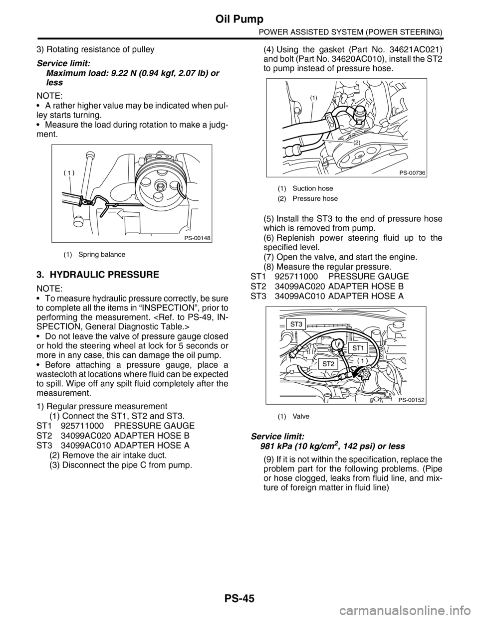
1) Regular pressure measurement
(1) Connect the ST1, ST2 and ST3.
ST1 925711000 PRESSURE GAUGE
ST2 34099AC020 ADAPTER HOSE B
ST3 34099AC010 ADAPTER HOSE A
(2) Remove the air intake duct.
(3) Disconnect the pipe C from pump.
(4) Using the gasket (Part No. 34621AC021)
and bolt (Part No. 34620AC010), install the ST2
to pump instead of pressure hose.
(5) Install the ST3 to the end of pressure hose
which is removed from pump.
(6) Replenish power steering fluid up to the
specified level.
(7) Open the valve, and start the engine.
(8) Measure the regular pressure.
ST1 925711000 PRESSURE GAUGE
ST2 34099AC020 ADAPTER HOSE B
ST3 34099AC010 ADAPTER HOSE A
Service limit:
981 kPa (10 kg/cm2, 142 psi) or less
(9) If it is not within the specification, replace the
problem part for the following problems. (Pipe
or hose clogged, leaks from fluid line, and mix-
ture of foreign matter in fluid line)
(1) Spring balance
PS-00148
(1) Suction hose
(2) Pressure hose
(1) Valve
PS-00736
(1)
(2)
PS-00152
Page 933 of 2453

PS-53
General Diagnostic Table
POWER ASSISTED SYSTEM (POWER STEERING)
3. INSPECTION OF CLEARANCE
This table lists various clearances that must be correctly adjusted to ensure the normal vehicle driving with-
out interfering noise, or any other faults.
Install locations Minimum allowance mm (in)
(1) Crossmember-to-Hose assembly 10 (0.39)
(2) Front frame side-to-Hose assembly 15 (0.59)
(3) Air bag sensor to cooler pipe assembly 10 (0.39)
(4) Air cleaner case-to-Suction hose 10 (0.39)
(5) VDCH/U to Reservoir tank bracket 10 (0.39)
(6) Air boots to Hose clip15 (0.59)
(7) Air boot-to-Hose assembly15 (0.59)
(8) Protector to Hose assembly10 (0.39)
(9) Intake manifold to Suction hose 10 (0.39)
(10) Intake manifold to hose assembly 10 (0.39)
(11) Air cleaner case to Cooler pipe joint block 5 (0.20)
(12) Chain cover to Cooler pipe joint block 20 (0.79)
(13) Oil pipe to Cooler pipe joint block 20 (0.79)
(14) Suction hose to Hose assembly 10 (0.39)
(15) Air boot to Reservoir tank10 (0.39)
(16) Brake pipe to Reservoir tank10 (0.39)
(17) Harness to Hose assembly10 (0.39)
(18) Relay box to Hose assembly15 (0.59)
(19) Bumper beam to Cooler pipe assembly 10 (0.39)
(20) Radiator bracket to Cooler pipe assembly 10 (0.39)
(21) ATF cooler to Cooler pipe assembly 10 (0.39)
(22) Undercover to cooler pipe assembly 10 (0.39)
(23) Protector to Hose assembly10 (0.39)
(24) Protector to Hose assembly15 (0.59)
(25) Return hose to Hose assembly 10 (0.39)
(26) Air cleaner case to Hose assembly 10 (0.39)
(27) Suction hose to Hose assembly 10 (0.39)
(28) Air cleaner case to Return hose 3 (0.12)
(29) Valve housing to DOJ12 (0.47)
(30) Valve housing to Crossmember 1 (0.04)
(31) Mount to Crossmember There must be no contact.
(32) Feed tube to Crossmember3 (0.12)
(33) Elbow to Crossmember3 (0.12)
(34) Cylinder pipe to Crossmember 3 (0.12)
(35) Feed tube to Exhaust pipe18 (0.71)
(36) Tie-rod end to Brake dust cover 2.5 (0.10)
(37) Coupling rubber to AT level gage 10 (0.39)
(38) Yoke to Brake booster5 (0.20)
Page 1125 of 2453

CO(H6DO)-6
General Description
COOLING
C: CAUTION
•Wear work clothing, including a cap, protective goggles and protective shoes during operation.
•Remove contamination including dirt and corrosion before removal, installation or disassembly.
•Keep the disassembled parts in order and protect them from dust and dirt.
•Before removal, installation or disassembly, be sure to clarify the failure. Avoid unnecessary removal, in-
stallation, disassembly and replacement.
•Be careful not to burn yourself, because each part on the vehicle is hot after running.
•Be sure to tighten fasteners including bolts and nuts to the specified torque.
•Place shop jacks or rigid racks at the specified points.
•Before disconnecting connectors of sensors or units, be sure to disconnect the ground cable from battery.
D: PREPARATION TOOL
1. SPECIAL TOOL
2. GENERAL TOOL
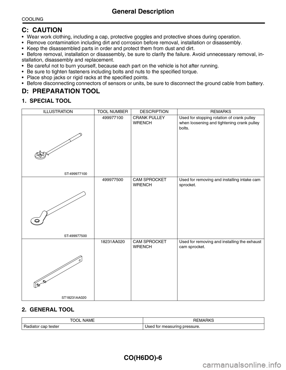
ILLUSTRATION TOOL NUMBER DESCRIPTION REMARKS
499977100 CRANK PULLEY
WRENCH
Used for stopping rotation of crank pulley
when loosening and tightening crank pulley
bolts.
499977500 CAM SPROCKET
WRENCH
Used for removing and installing intake cam
sprocket.
18231AA020 CAM SPROCKET
WRENCH
Used for removing and installing the exhaust
cam sprocket.
TOOL NAME REMARKS
Radiator cap tester Used for measuring pressure.
ST-499977100
ST-499977500
ST18231AA020
Page 1134 of 2453
CO(H6DO)-15
Radiator
COOLING
6. Radiator
A: REMOVAL
WARNING:
The radiator is pressurized. Wait until engine
cools down before working on the radiator.
1) Set the vehicle on a lift.
2) Remove the collector cover.
3) Disconnect the ground cable from battery.
4) Lift-up the vehicle.
5) Remove the under cover.
6) Drain engine coolant completely.
COOLANT, REPLACEMENT, Engine Coolant.>
7) Disconnect the radiator hose from radiator.
8) Remove the bolts on the underside of the radia-
tor stay.
9) Lower the vehicle.
10) Remove the air intake duct.
7, REMOVAL, Air Intake Duct.>
11) Remove the front upper cover.
12) Remove the radiator upper brackets.
13) Remove the radiator stay.
(1) Remove the latch.
(2) Remove the radiator hose bracket.
(3) Remove the clip holding the harness.
(4) Remove the bolts on the left side of the radi-
ator stay.
CO-02015
CO-02175
CO-02176
CO-02177
CO-02179
CO-02180
Page 1138 of 2453

CO(H6DO)-19
Radiator
COOLING
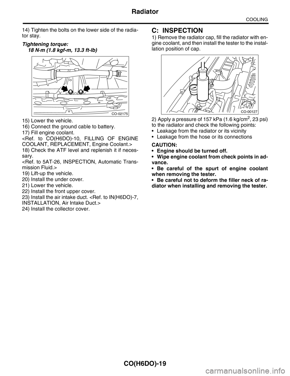
14) Tighten the bolts on the lower side of the radia-
tor stay.
Tightening torque:
18 N·m (1.8 kgf-m, 13.3 ft-lb)
15) Lower the vehicle.
16) Connect the ground cable to battery.
17) Fill engine coolant.
COOLANT, REPLACEMENT, Engine Coolant.>
18) Check the ATF level and replenish it if neces-
sary.
mission Fluid.>
19) Lift-up the vehicle.
20) Install the under cover.
21) Lower the vehicle.
22) Install the front upper cover.
23) Install the air intake duct.
INSTALLATION, Air Intake Duct.>
24) Install the collector cover.
C: INSPECTION
1) Remove the radiator cap, fill the radiator with en-
gine coolant, and then install the tester to the instal-
lation position of cap.
2) Apply a pressure of 157 kPa (1.6 kg/cm2, 23 psi)
to the radiator and check the following points:
•Leakage from the radiator or its vicinity
•Leakage from the hose or its connections
CAUTION:
•Engine should be turned off.
•Wipe engine coolant from check points in ad-
vance.
•Be careful of the spurt of engine coolant
when removing the tester.
•Be careful not to deform the filler neck of ra-
diator when installing and removing the tester.
CO-02175CO-00127
Page 1140 of 2453
CO(H6DO)-21
Radiator Main Fan and Fan Motor
COOLING
8. Radiator Main Fan and Fan
Motor
A: REMOVAL
1) Set the vehicle on a lift.
2) Remove the collector cover.
3) Disconnect the ground cable from battery.
4) Lift-up the vehicle.
5) Remove the under cover.
6) Remove the bolts on the underside of the radia-
tor stay.
7) Remove the bolts on the underside of the radia-
tor fan shroud.
8) Lower the vehicle.
9) Remove the air intake duct.
7, REMOVAL, Air Intake Duct.>
10) Remove the front upper cover.
11) Remove the radiator upper brackets.
12) Remove the radiator stay.
(1) Remove the latch.
(2) Remove the radiator hose bracket.
(3) Remove the clip holding the harness.
(4) Remove the bolts on the left side of the radi-
ator stay.
CO-02175
CO-02188
CO-02176
CO-02177
CO-02179
CO-02180