Page 2096 of 2453
5AT-80
Oil Pump Cover
AUTOMATIC TRANSMISSION
E: INSPECTION
1. FRONT BRAKE
Check the following items.
•Drive plate facing for wear and damage
•Snap ring for wear, return spring for damage,
and retainer for damage
•Piston for damage
•D-ring for damage
2. OIL PUMP
Check the following items.
•Oil pump cover and oil seal for breakage or dam-
age
•Oil pump body for scratch or damage
1) Check the seal ring and oil seal for breaks and
damage.
2) Check other parts for dents or faults.
3) Oil pump rotor assembly selection
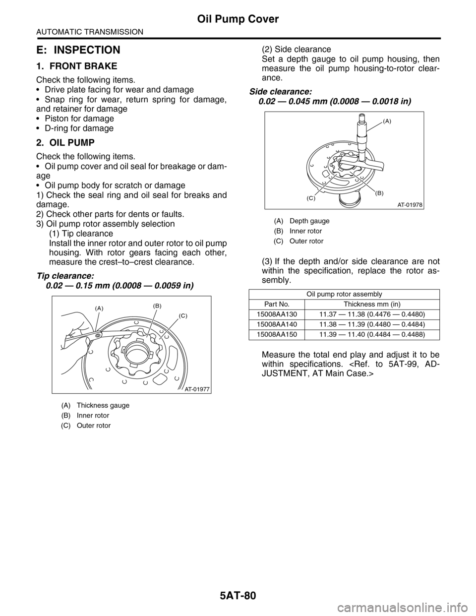
(1) Tip clearance
Install the inner rotor and outer rotor to oil pump
housing. With rotor gears facing each other,
measure the crest–to–crest clearance.
Tip clearance:
0.02 — 0.15 mm (0.0008 — 0.0059 in)
(2) Side clearance
Set a depth gauge to oil pump housing, then
measure the oil pump housing-to-rotor clear-
ance.
Side clearance:
0.02 — 0.045 mm (0.0008 — 0.0018 in)
(3) If the depth and/or side clearance are not
within the specification, replace the rotor as-
sembly.
Measure the total end play and adjust it to be
within specifications.
JUSTMENT, AT Main Case.>
(A) Thickness gauge
(B) Inner rotor
(C) Outer rotor
AT-01977
(A)(B)
(C)
(A) Depth gauge
(B) Inner rotor
(C) Outer rotor
Oil pump rotor assembly
Par t No. Thickness mm (in)
15008AA130 11.37 — 11.38 (0.4476 — 0.4480)
15008AA140 11.38 — 11.39 (0.4480 — 0.4484)
15008AA150 11.39 — 11.40 (0.4484 — 0.4488)
AT-01978
(A)
(C)(B)
Page 2099 of 2453
5AT-83
Drive Pinion Shaft Assembly
AUTOMATIC TRANSMISSION
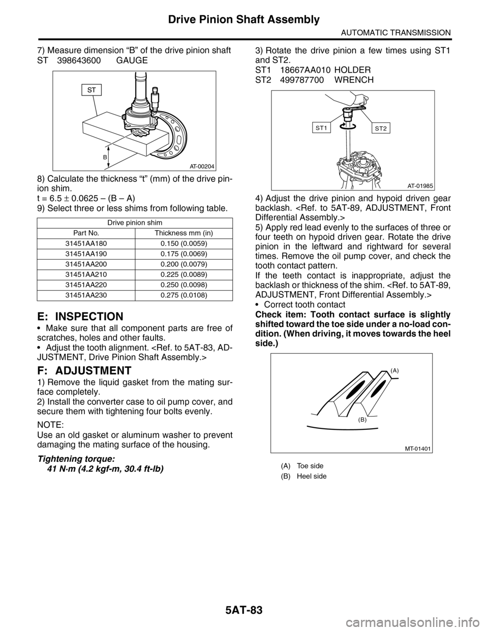
7) Measure dimension “B” of the drive pinion shaft
ST 398643600 GAUGE
8) Calculate the thickness “t” (mm) of the drive pin-
ion shim.
t = 6.5 ± 0.0625 – (B – A)
9) Select three or less shims from following table.
E: INSPECTION
•Make sure that all component parts are free of
scratches, holes and other faults.
•Adjust the tooth alignment.
JUSTMENT, Drive Pinion Shaft Assembly.>
F: ADJUSTMENT
1) Remove the liquid gasket from the mating sur-
face completely.
2) Install the converter case to oil pump cover, and
secure them with tightening four bolts evenly.
NOTE:
Use an old gasket or aluminum washer to prevent
damaging the mating surface of the housing.
Tightening torque:
41 N·m (4.2 kgf-m, 30.4 ft-lb)
3) Rotate the drive pinion a few times using ST1
and ST2.
ST1 18667AA010 HOLDER
ST2 499787700 WRENCH
4) Adjust the drive pinion and hypoid driven gear
backlash.
Differential Assembly.>
5) Apply red lead evenly to the surfaces of three or
four teeth on hypoid driven gear. Rotate the drive
pinion in the leftward and rightward for several
times. Remove the oil pump cover, and check the
tooth contact pattern.
If the teeth contact is inappropriate, adjust the
backlash or thickness of the shim.
ADJUSTMENT, Front Differential Assembly.>
•Correct tooth contact
Check item: Tooth contact surface is slightly
shifted toward the toe side under a no-load con-
dition. (When driving, it moves towards the heel
side.)
Drive pinion shim
Par t No. Thickness mm (in)
31451AA180 0.150 (0.0059)
31451AA190 0.175 (0.0069)
31451AA200 0.200 (0.0079)
31451AA210 0.225 (0.0089)
31451AA220 0.250 (0.0098)
31451AA230 0.275 (0.0108)
B
AT-00204
(A) Toe side
(B) Heel side
AT-01985
ST2ST1
MT-01401
(A)
(B)
Page 2101 of 2453
5AT-85
Drive Pinion Shaft Assembly
AUTOMATIC TRANSMISSION
6) If tooth contact is correct, mark the retainer posi-
tion and loosen it. After fitting a new O-ring and oil
seal, screw in the retainer to the marked position.
Tighten the lock plate with specified torque.
Tightening torque:
25 N·m (2.5 kgf-m, 18 ft-lb)
(A) Lock plate
AT-01988
(A)
Page 2105 of 2453
5AT-89
Front Differential Assembly
AUTOMATIC TRANSMISSION
2. SIDE RETAINER
NOTE:
Install the oil seal and O-ring of side retainer after
the adjustment of backlash and tooth contact.
1) Install the bearing outer race to side retainer.
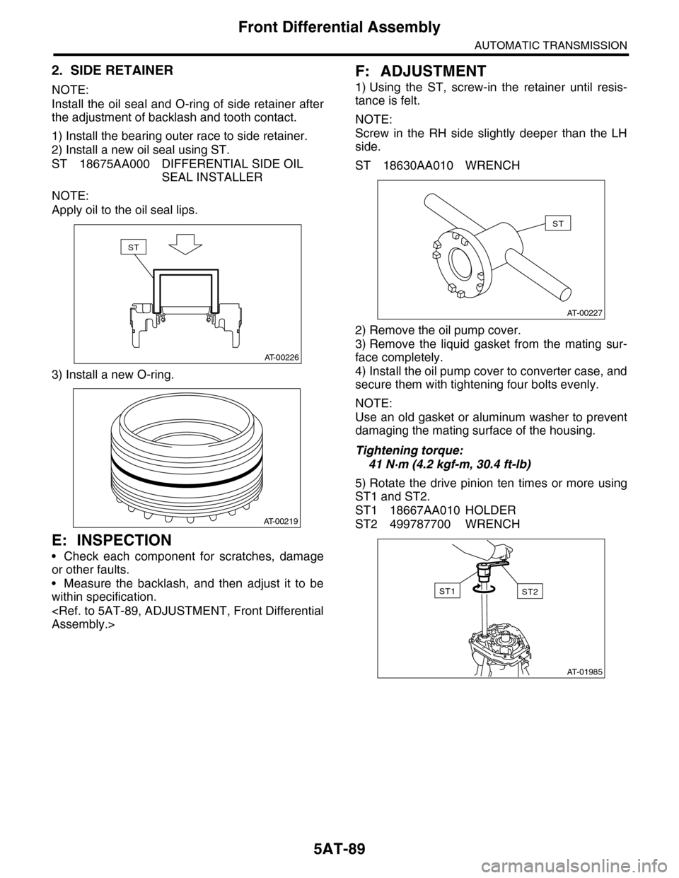
2) Install a new oil seal using ST.
ST 18675AA000 DIFFERENTIAL SIDE OIL
SEAL INSTALLER
NOTE:
Apply oil to the oil seal lips.
3) Install a new O-ring.
E: INSPECTION
•Check each component for scratches, damage
or other faults.
•Measure the backlash, and then adjust it to be
within specification.
Assembly.>
F: ADJUSTMENT
1) Using the ST, screw-in the retainer until resis-
tance is felt.
NOTE:
Screw in the RH side slightly deeper than the LH
side.
ST 18630AA010 WRENCH
2) Remove the oil pump cover.
3) Remove the liquid gasket from the mating sur-
face completely.
4) Install the oil pump cover to converter case, and
secure them with tightening four bolts evenly.
NOTE:
Use an old gasket or aluminum washer to prevent
damaging the mating surface of the housing.
Tightening torque:
41 N·m (4.2 kgf-m, 30.4 ft-lb)
5) Rotate the drive pinion ten times or more using
ST1 and ST2.
ST1 18667AA010 HOLDER
ST2 499787700 WRENCH
AT-00226
ST
AT-00219
AT-00227
ST
AT-01985
ST2ST1
Page 2113 of 2453
5AT-97
AT Main Case
AUTOMATIC TRANSMISSION
24) Install the extension case.
STALLATION, Extension Case.>
25) Install the control valve body.
INSTALLATION, Control Valve Body.>
26) Install the converter case assembly to the
transmission case assembly.
STALLATION, Converter Case.>
27) Install the air breather hose.
INSTALLATION, Air Breather Hose.>
28) Install the ATF filter pipe.
STALLATION, ATF Cooler Pipe & Hose.>
29) Install the oil charge pipe together with an O-
ring.
Pipe.>
30) Install the torque converter assembly.
5AT-62, INSTALLATION, Torque Converter As-
sembly.>
31) Install the transmission assembly to the vehi-
cle.
Transmission Assembly.>
32) Perform Clear Memory 2 operation.
5AT(diag)-17, CLEAR MEMORY MODE, OPERA-
TION, Subaru Select Monitor.>
33) Perform the inspection with driving the vehicle
at the end of repair work, and make sure there is no
faulty as below;
•Excessive shift shock
•Oil leakage from the transmission body, etc.
•Occurrence of noise caused by interference etc.
NOTE:
If excessive shift shock is felt, execute advance op-
eration of learning control.
PROCEDURE, Learning Control.>
C: DISASSEMBLY
1. INPUT CLUTCH PACK ASSEMBLY
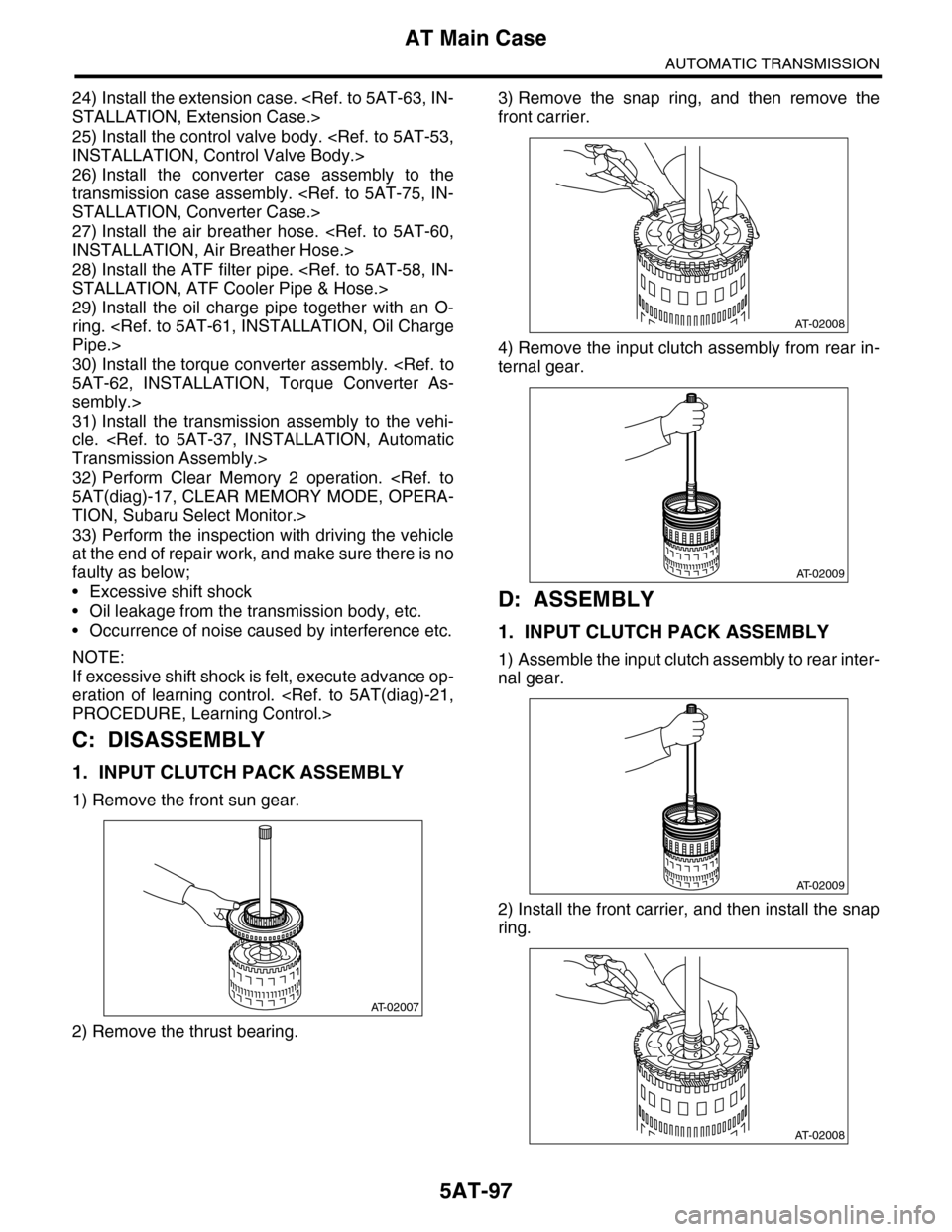
1) Remove the front sun gear.
2) Remove the thrust bearing.
3) Remove the snap ring, and then remove the
front carrier.
4) Remove the input clutch assembly from rear in-
ternal gear.
D: ASSEMBLY
1. INPUT CLUTCH PACK ASSEMBLY
1) Assemble the input clutch assembly to rear inter-
nal gear.
2) Install the front carrier, and then install the snap
ring.
AT-02007
AT-02008
AT-02009
AT-02009
AT-02008
Page 2117 of 2453
5AT-101
Transmission Control Device
AUTOMATIC TRANSMISSION
3) Insert the manual plate and parking rod.
4) Insert the spring pin to the manual plate.
5) Install the oil pan and the control valve assem-
bly.
Valve Body.>
6) Install the pitching stopper bracket.
Tightening torque:
41 N·m (4.2 kgf-m, 30.4 ft-lb)
7) Insert the transmission connector to the stay.
8) Install the air breather hose.
STALLATION, Air Breather Hose.>
9) Install the torque converter assembly.
5AT-62, INSTALLATION, Torque Converter As-
sembly.>
10) Install the transmission assembly to the vehi-
cle.
Transmission Assembly.>
C: INSPECTION
Make sure the manual lever and detention spring
are not worn or otherwise damaged.
(A) Bolt
(B) Range select lever
(C) Manual plate
(D) Parking rod
AT-00306
AT-00305
Page 2119 of 2453
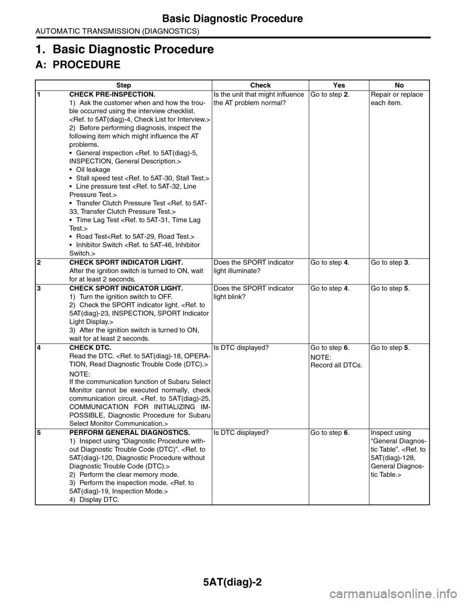
5AT(diag)-2
Basic Diagnostic Procedure
AUTOMATIC TRANSMISSION (DIAGNOSTICS)
1. Basic Diagnostic Procedure
A: PROCEDURE
Step Check Yes No
1CHECK PRE-INSPECTION.
1) Ask the customer when and how the trou-
ble occurred using the interview checklist.
2) Before performing diagnosis, inspect the
following item which might influence the AT
problems.
•General inspection
INSPECTION, General Description.>
•Oil leakage
•Stall speed test
•Line pressure test
Pressure Test.>
•Transfer Clutch Pressure Test
33, Transfer Clutch Pressure Test.>
•Time Lag Test
Te s t . >
•Road Test
•Inhibitor Switch
Switch.>
Is the unit that might influence
the AT problem normal?
Go to step 2.Repair or replace
each item.
2CHECK SPORT INDICATOR LIGHT.
After the ignition switch is turned to ON, wait
for at least 2 seconds.
Does the SPORT indicator
light illuminate?
Go to step 4.Go to step 3.
3CHECK SPORT INDICATOR LIGHT.
1) Turn the ignition switch to OFF.
2) Check the SPORT indicator light.
5AT(diag)-23, INSPECTION, SPORT Indicator
Light Display.>
3) After the ignition switch is turned to ON,
wait for at least 2 seconds.
Does the SPORT indicator
light blink?
Go to step 4.Go to step 5.
4CHECK DTC.
Read the DTC.
TION, Read Diagnostic Trouble Code (DTC).>
NOTE:If the communication function of Subaru Select
Monitor cannot be executed normally, check
communication circuit.
COMMUNICATION FOR INITIALIZING IM-
POSSIBLE, Diagnostic Procedure for Subaru
Select Monitor Communication.>
Is DTC displayed? Go to step 6.
NOTE:
Record all DTCs.
Go to step 5.
5PERFORM GENERAL DIAGNOSTICS.
1) Inspect using “Diagnostic Procedure with-
out Diagnostic Trouble Code (DTC)”.
5AT(diag)-120, Diagnostic Procedure without
Diagnostic Trouble Code (DTC).>
2) Perform the clear memory mode.
3) Perform the inspection mode.
5AT(diag)-19, Inspection Mode.>
4) Display DTC.
Is DTC displayed? Go to step 6.Inspect using
“General Diagnos-
tic Table”.
5AT(diag)-128,
General Diagnos-
tic Table.>
Page 2122 of 2453
5AT(diag)-5
General Description
AUTOMATIC TRANSMISSION (DIAGNOSTICS)
3. General Description
A: CAUTION
•SRS AIRBAG SYSTEM
The airbag system wiring harness is routed near
the TCM.
CAUTION:
•All air bag system wiring harnesses and con-
nectors are colored yellow. Do not use an elec-
tric test equipment to check these circuits.
•Be careful not to damage the airbag system
wiring harness when performing diagnostics or
servicing the TCM.
•MEASUREMENT
When measuring the voltage and resistance of the
ECM, TCM or each sensor, use a tapered pin with
a diameter of less than 0.64 mm (0.025 in) in order
to avoid poor contact. Do not insert a pin of more
than 0.65 mm (0.026 in) diameter.
B: INSPECTION
1. BATTERY
Measure the battery voltage and specific gravity of
electrolyte.
Standard voltage: 12 V or more
Specific gravity: 1.260 or more
2. TRANSMISSION GROUND
Make sure that the ground terminal bolt is tightened
securely.
Tightening torque:
13 N·m (1.3 kgf-m, 9.4 ft-lb)
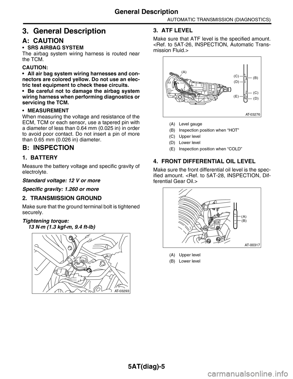
3. ATF LEVEL
Make sure that ATF level is the specified amount.
mission Fluid.>
4. FRONT DIFFERENTIAL OIL LEVEL
Make sure the front differential oil level is the spec-
ified amount.
ferential Gear Oil.>
AT-03293
(A) Level gauge
(B) Inspection position when “HOT”
(C) Upper level
(D) Lower level
(E) Inspection position when “COLD”
(A) Upper level
(B) Lower level
AT-03276
COLDLF
HOTLF
(C)
(D)
(C)
(D)
(E)
(B)
(A)
AT-00317
(A)(B)L
F