Page 2072 of 2453

5AT-56
Transmission Control Module (TCM)
AUTOMATIC TRANSMISSION
19.Transmission Control Mod-
ule (TCM)
A: REMOVAL
1) Disconnect the ground cable from battery.
2) Remove the lower cover and then disconnect
the connector.
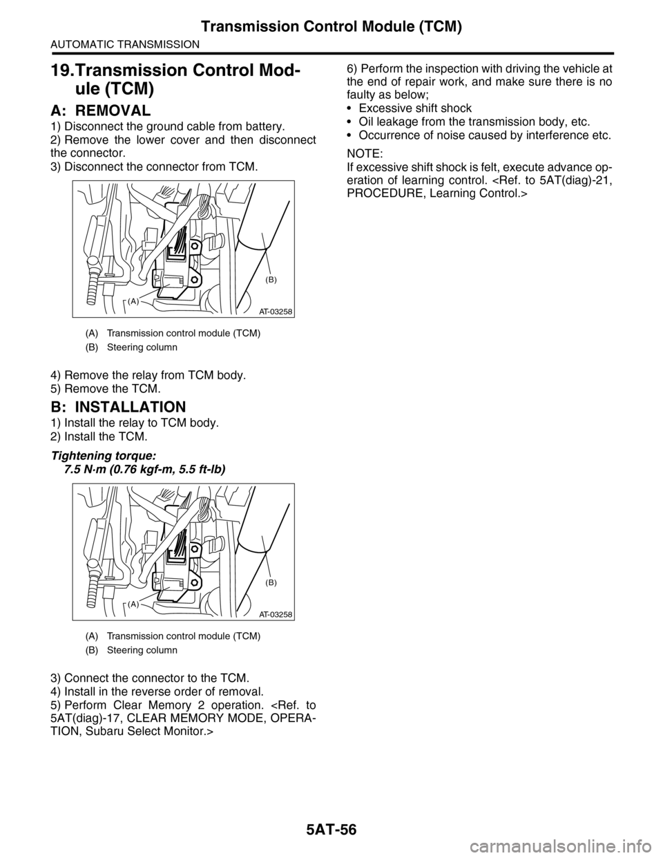
3) Disconnect the connector from TCM.
4) Remove the relay from TCM body.
5) Remove the TCM.
B: INSTALLATION
1) Install the relay to TCM body.
2) Install the TCM.
Tightening torque:
7.5 N·m (0.76 kgf-m, 5.5 ft-lb)
3) Connect the connector to the TCM.
4) Install in the reverse order of removal.
5) Perform Clear Memory 2 operation.
5AT(diag)-17, CLEAR MEMORY MODE, OPERA-
TION, Subaru Select Monitor.>
6) Perform the inspection with driving the vehicle at
the end of repair work, and make sure there is no
faulty as below;
•Excessive shift shock
•Oil leakage from the transmission body, etc.
•Occurrence of noise caused by interference etc.
NOTE:
If excessive shift shock is felt, execute advance op-
eration of learning control.
PROCEDURE, Learning Control.>
(A) Transmission control module (TCM)
(B) Steering column
(A) Transmission control module (TCM)
(B) Steering column
AT-03258(A)
(B)
AT-03258(A)
(B)
Page 2077 of 2453
5AT-61
Oil Charge Pipe
AUTOMATIC TRANSMISSION
22.Oil Charge Pipe
A: REMOVAL
1) Remove the air intake chamber.
IN(H6DO)-6, REMOVAL, Air Intake Chamber.>
2) Remove the oil charge pipe, and then remove
the O-ring from flange side.
B: INSTALLATION
1) Install the oil charge pipe with a new O-ring.
Tightening torque:
41 N·m (4.2 kgf-m, 30.4 ft-lb)
2) Install the air intake chamber.
IN(H6DO)-6, INSTALLATION, Air Intake Cham-
ber.>
C: INSPECTION
Make sure the oil charge pipe is not deformed or
damaged.
(A) Oil level gauge
(B) Oil charge pipe
(A) Oil level gauge
(B) Oil charge pipe
AT-01386
(B)
(A)
AT-01386
(B)
(A)
Page 2078 of 2453

5AT-62
Torque Converter Assembly
AUTOMATIC TRANSMISSION
23.Torque Converter Assembly
A: REMOVAL
1) Remove the transmission assembly from vehicle
body.
Transmission Assembly.>
2) Pull out the torque converter and oil pump shaft
horizontally.
NOTE:
•Be sure not to scratch the inside of bushing in oil
pump shaft.
•Be careful that the oil pump shaft may drawn out
simultaneously.
3) Remove the oil pump shaft from torque convert-
er as necessary.
B: INSTALLATION
1) When the oil pump shaft is removed, install the
shaft to torque converter.
NOTE:
Make sure the clip is firmly inserted.
2) Install the oil pump shaft to torque converter, and
then make sure that the clip is secured on groove.
3) Apply ATF to the revolving and sliding surface of
the oil pump shaft.
4) Holding the torque converter assembly by hand,
lightly rotate it to engage with the oil pump rotor.
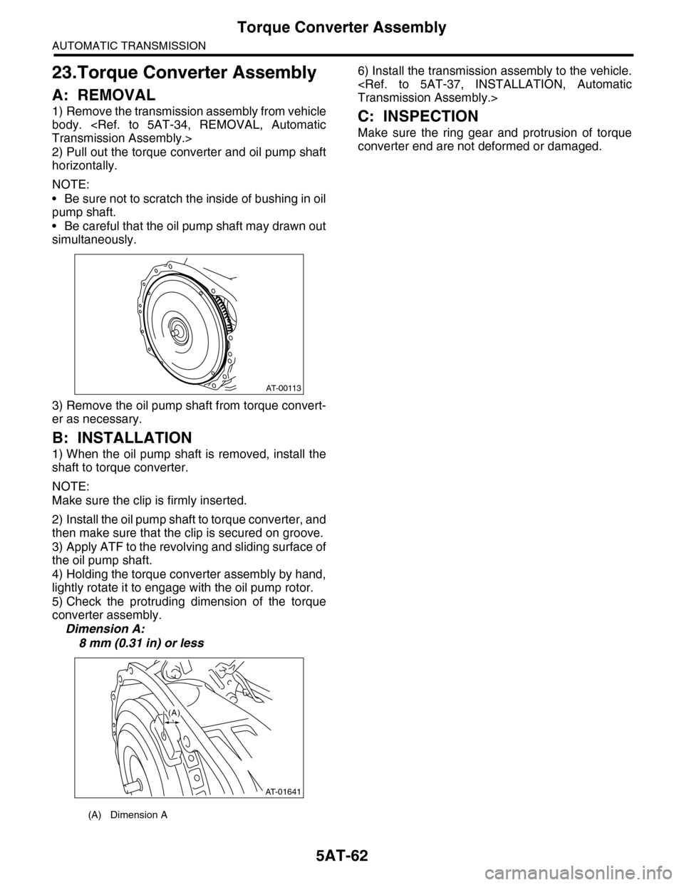
5) Check the protruding dimension of the torque
converter assembly.
Dimension A:
8 mm (0.31 in) or less
6) Install the transmission assembly to the vehicle.
Transmission Assembly.>
C: INSPECTION
Make sure the ring gear and protrusion of torque
converter end are not deformed or damaged.
(A) Dimension A
AT-00113
AT-01641
(A)
Page 2079 of 2453

5AT-63
Extension Case
AUTOMATIC TRANSMISSION
24.Extension Case
A: REMOVAL
1) Remove the transmission assembly.
sion Assembly.>
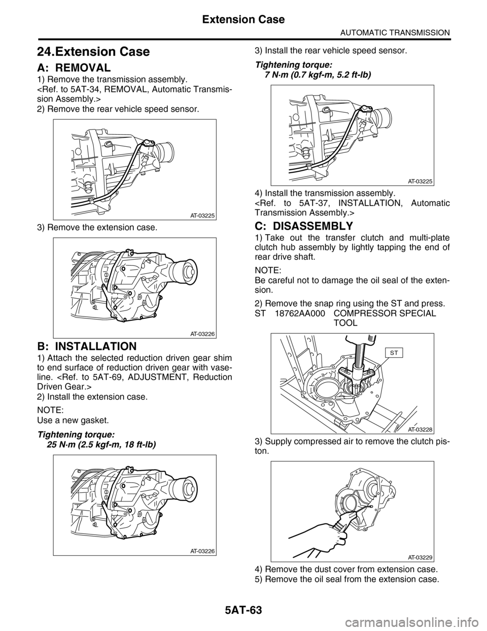
2) Remove the rear vehicle speed sensor.
3) Remove the extension case.
B: INSTALLATION
1) Attach the selected reduction driven gear shim
to end surface of reduction driven gear with vase-
line.
Driven Gear.>
2) Install the extension case.
NOTE:
Use a new gasket.
Tightening torque:
25 N·m (2.5 kgf-m, 18 ft-lb)
3) Install the rear vehicle speed sensor.
Tightening torque:
7 N·m (0.7 kgf-m, 5.2 ft-lb)
4) Install the transmission assembly.
Transmission Assembly.>
C: DISASSEMBLY
1) Take out the transfer clutch and multi-plate
clutch hub assembly by lightly tapping the end of
rear drive shaft.
NOTE:
Be careful not to damage the oil seal of the exten-
sion.
2) Remove the snap ring using the ST and press.
ST 18762AA000 COMPRESSOR SPECIAL
TOOL
3) Supply compressed air to remove the clutch pis-
ton.
4) Remove the dust cover from extension case.
5) Remove the oil seal from the extension case.
AT-03225
AT-03226
AT-03226
AT-03225
AT-03228
ST
AT-03229
Page 2080 of 2453
5AT-64
Extension Case
AUTOMATIC TRANSMISSION
D: ASSEMBLY
1) Press-fit the new oil seal using ST and the press.
ST 498057300 INSTALLER
2) Press-fit the dust cover.
3) Insert the transfer clutch assembly, spring re-
tainer, return spring and clutch spring retainer.
4) Using the ST and compressor, install the snap
ring.
ST 18762AA000 COMPRESSOR SPECIAL
TOOL
5) Install the transfer clutch.
STALLATION, Transfer Clutch.>
6) Install the multi-plate hub assembly.
E: INSPECTION
•Use compressed air to make sure the extension
case routes are not clogged or leaking.
•Inspect the extension end play, and adjust it to
within the standard value.
(A) Clutch spring retainer
(B) Return spring
(C) Spring retainer
(D) Transfer clutch piston
AT-03230
(A)(B)(C)
(D)
AT-03228
ST
Page 2092 of 2453
5AT-76
Converter Case
AUTOMATIC TRANSMISSION
7) Install the three converter case mounting bolts
(TORX®).
ST 18676AA020 TORX® WRENCH
Tightening torque:
41 N·m (4.2 kgf-m, 30.4 ft-lb)
8) Apply proper amount of liquid gasket to the en-
tire oil pan mating surface, and then install it.
Liquid gasket:
THREE BOND 1217B (Part No. K0877YA020)
Tightening torque:
5 N·m (0.5 kgf-m, 3.7 ft-lb)
9) Install the transmission harness connector to the
stay.
10) Install the air breather hose.
INSTALLATION, Air Breather Hose.>
11) Install the ATF filter pipe.
STALLATION, ATF Cooler Pipe & Hose.>
12) Install the oil charge pipe with O-ring.
5AT-61, INSTALLATION, Oil Charge Pipe.>
13) Install the torque converter assembly.
5AT-62, INSTALLATION, Torque Converter As-
sembly.>
14) Install the transmission assembly to the vehi-
cle.
Transmission Assembly.>
C: INSPECTION
Measure the backlash, and then adjust it to be with-
in standard values.
MENT, Drive Pinion Shaft Assembly.>
AT-01974
AT-03249
Page 2094 of 2453

5AT-78
Oil Pump Cover
AUTOMATIC TRANSMISSION
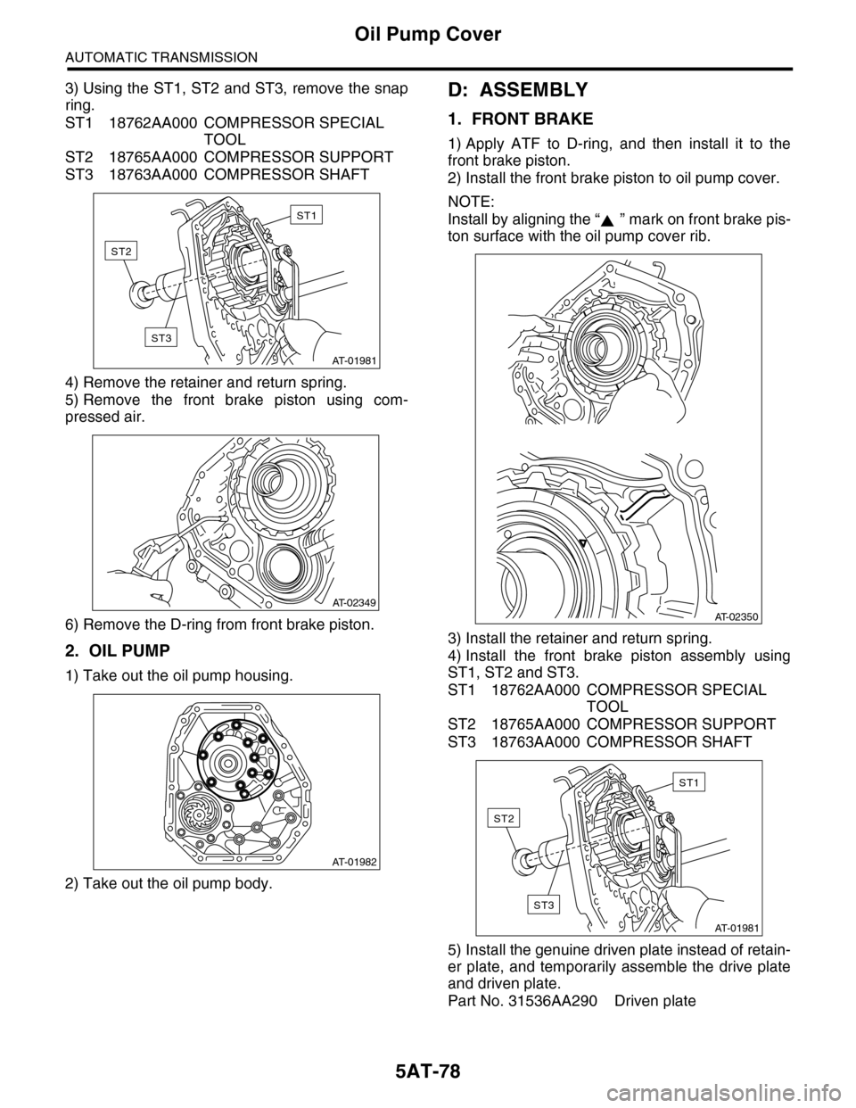
3) Using the ST1, ST2 and ST3, remove the snap
ring.
ST1 18762AA000 COMPRESSOR SPECIAL
TOOL
ST2 18765AA000 COMPRESSOR SUPPORT
ST3 18763AA000 COMPRESSOR SHAFT
4) Remove the retainer and return spring.
5) Remove the front brake piston using com-
pressed air.
6) Remove the D-ring from front brake piston.
2. OIL PUMP
1) Take out the oil pump housing.
2) Take out the oil pump body.
D: ASSEMBLY
1. FRONT BRAKE
1) Apply ATF to D-ring, and then install it to the
front brake piston.
2) Install the front brake piston to oil pump cover.
NOTE:
Install by aligning the “ ” mark on front brake pis-
ton surface with the oil pump cover rib.
3) Install the retainer and return spring.
4) Install the front brake piston assembly using
ST1, ST2 and ST3.
ST1 18762AA000 COMPRESSOR SPECIAL
TOOL
ST2 18765AA000 COMPRESSOR SUPPORT
ST3 18763AA000 COMPRESSOR SHAFT
5) Install the genuine driven plate instead of retain-
er plate, and temporarily assemble the drive plate
and driven plate.
Part No. 31536AA290 Driven plate
AT-01981
ST1
ST2
ST3
AT-02349
AT-01982
AT-02350
AT-01981
ST1
ST2
ST3
Page 2095 of 2453
5AT-79
Oil Pump Cover
AUTOMATIC TRANSMISSION
6) Install the snap ring.
7) Measure the clearance between retainer plate
and snap ring, and then select the suitable retainer
plate from table.
Front brake clearance specification:
0.7 — 1.1 mm (0.028 — 0.043 in)
8) Remove the snap ring, replace the driven plate
used in measurement of clearance with the retainer
plate, and then reassemble.
2. OIL PUMP
1) Apply ATF to oil pump assembly, and then install
it to oil pump housing.
2) Install the O-ring to oil pump cover.
3) Install the oil pump housing to the oil pump cov-
er.
Tightening torque:
10 N·m (1.0 kgf-m, 7.4 ft-lb)
Front brake retainer plate
Par t No. Thickness mm (in)
31567AB130 3.4 (0.134)
31567AB140 3.6 (0.142)
31567AB150 3.8 (0.150)
31567AB160 4.0 (0.157)
AT-01980
AT-01983
AT-01982