2009 SUBARU TRIBECA fuel
[x] Cancel search: fuelPage 1619 of 2453
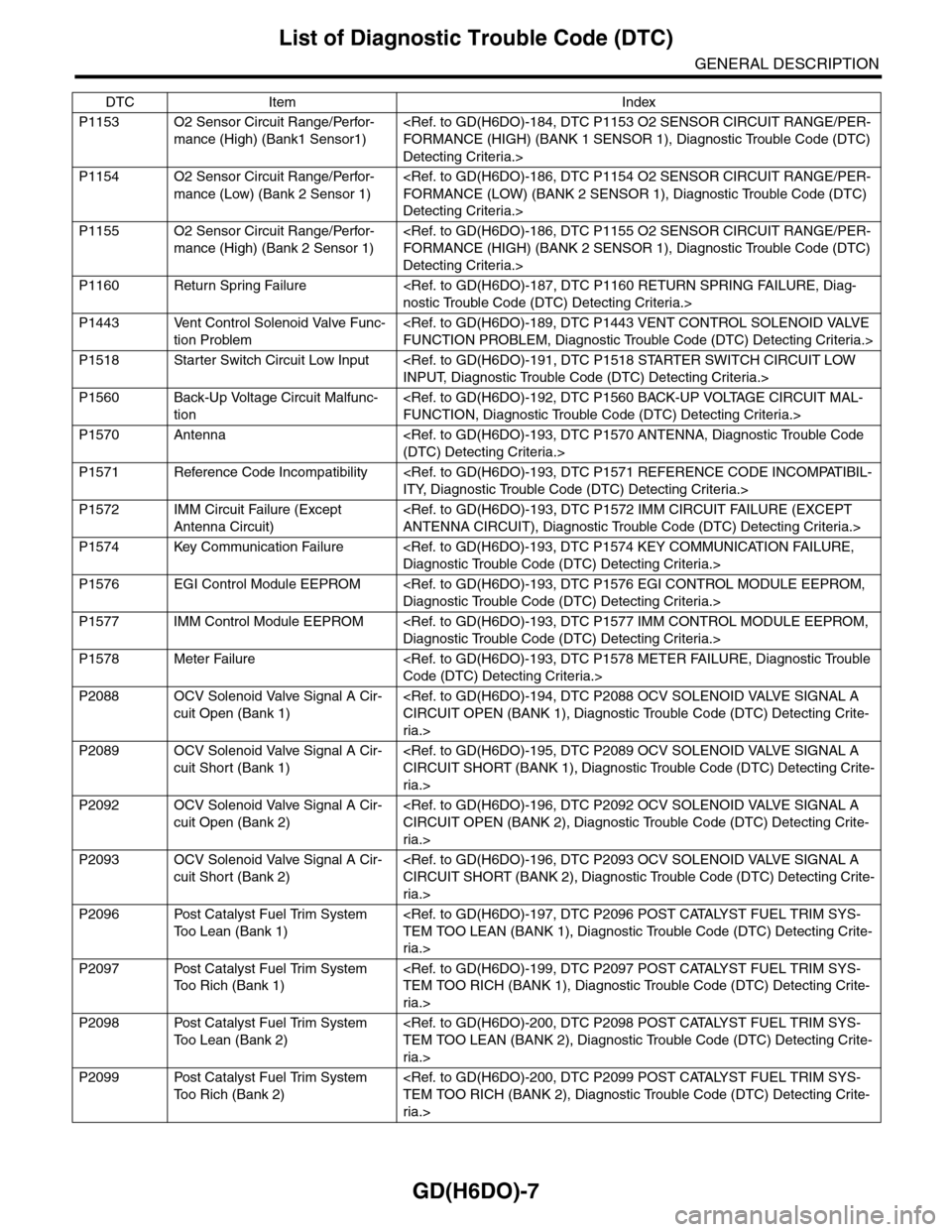
GD(H6DO)-7
List of Diagnostic Trouble Code (DTC)
GENERAL DESCRIPTION
P1153 O2 Sensor Circuit Range/Perfor-
mance (High) (Bank1 Sensor1)
Detecting Criteria.>
P1154 O2 Sensor Circuit Range/Perfor-
mance (Low) (Bank 2 Sensor 1)
Detecting Criteria.>
P1155 O2 Sensor Circuit Range/Perfor-
mance (High) (Bank 2 Sensor 1)
Detecting Criteria.>
P1160 Return Spring Failure
P1443 Vent Control Solenoid Valve Func-
tion Problem
P1518 Starter Switch Circuit Low Input
P1560 Back-Up Voltage Circuit Malfunc-
tion
P1570 Antenna
P1571 Reference Code Incompatibility
P1572 IMM Circuit Failure (Except
Antenna Circuit)
P1574 Key Communication Failure
P1576 EGI Control Module EEPROM
P1577 IMM Control Module EEPROM
P1578 Meter Failure
P2088 OCV Solenoid Valve Signal A Cir-
cuit Open (Bank 1)
ria.>
P2089 OCV Solenoid Valve Signal A Cir-
cuit Short (Bank 1)
ria.>
P2092 OCV Solenoid Valve Signal A Cir-
cuit Open (Bank 2)
ria.>
P2093 OCV Solenoid Valve Signal A Cir-
cuit Short (Bank 2)
ria.>
P2096 Post Catalyst Fuel Trim System
To o L e a n ( B a n k 1 )
ria.>
P2097 Post Catalyst Fuel Trim System
To o R i c h ( B a n k 1 )
ria.>
P2098 Post Catalyst Fuel Trim System
To o L e a n ( B a n k 2 )
ria.>
P2099 Post Catalyst Fuel Trim System
To o R i c h ( B a n k 2 )
ria.>
DTC Item Index
Page 1627 of 2453
GD(H6DO)-15
Diagnostic Trouble Code (DTC) Detecting Criteria
GENERAL DESCRIPTION
F: DTC P0028 INTAKE VALVE CONTROL SOLENOID CIRCUIT RANGE/PER-
FORMANCE (BANK 2)
NOTE:
For diagnostic procedures, refer to DTC P0026.
Criteria.>
G: DTC P0030 HO2S HEATER CONTROL CIRCUIT (BANK 1 SENSOR 1)
1. OUTLINE OF DIAGNOSIS
Detect functional errors of the front oxygen (A/F) sensor heater.
Judge as NG when it is determined that the front oxygen (A/F) sensor impedance is large when looking at en-
gine status such as deceleration fuel cut.
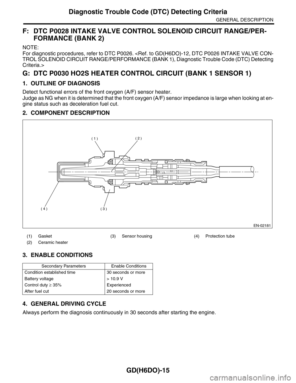
2. COMPONENT DESCRIPTION
3. ENABLE CONDITIONS
4. GENERAL DRIVING CYCLE
Always perform the diagnosis continuously in 30 seconds after starting the engine.
(1) Gasket (3) Sensor housing (4) Protection tube
(2) Ceramic heater
Secondary Parameters Enable Conditions
Condition established time 30 seconds or more
Battery voltage > 10.9 V
Control duty ≥ 35% Experienced
After fuel cut 20 seconds or more
EN-02181
( 1 )( 2 )
( 3 )( 4 )
Page 1644 of 2453
GD(H6DO)-32
Diagnostic Trouble Code (DTC) Detecting Criteria
GENERAL DESCRIPTION
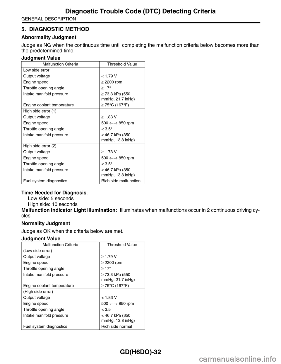
5. DIAGNOSTIC METHOD
Abnormality Judgment
Judge as NG when the continuous time until completing the malfunction criteria below becomes more than
the predetermined time.
Time Needed for Diagnosis:
Low side: 5 seconds
High side: 10 seconds
Malfunction Indicator Light Illumination: Illuminates when malfunctions occur in 2 continuous driving cy-
cles.
Normality Judgment
Judge as OK when the criteria below are met.
Judgment Value
Malfunction Criteria Threshold Value
Low side error
Output voltage < 1.79 V
Engine speed≥ 2200 rpm
Throttle opening angle≥ 17°
Intake manifold pressure≥ 73.3 kPa (550
mmHg, 21.7 inHg)
Engine coolant temperature≥ 75°C (167°F)
High side error (1)
Output voltage≥ 1.83 V
Engine speed 500 ←→ 850 rpm
Throttle opening angle < 3.5°
Intake manifold pressure < 46.7 kPa (350
mmHg, 13.8 inHg)
High side error (2)
Output voltage≥ 1.73 V
Engine speed 500 ←→ 850 rpm
Throttle opening angle < 3.5°
Intake manifold pressure < 46.7 kPa (350
mmHg, 13.8 inHg)
Fuel system diagnostics Rich side malfunction
Judgment Value
Malfunction Criteria Threshold Value
(Low side error)
Output voltage≥ 1.79 V
Engine speed≥ 2200 rpm
Throttle opening angle≥ 17°
Intake manifold pressure≥ 73.3 kPa (550
mmHg, 21.7 inHg)
Engine coolant temperature≥ 75°C (167°F)
(High side error)
Output voltage < 1.83 V
Engine speed 500 ←→ 850 rpm
Throttle opening angle < 3.5°
Intake manifold pressure < 46.7 kPa (350
mmHg, 13.8 inHg)
Fuel system diagnostics Rich side normal
Page 1668 of 2453
GD(H6DO)-56
Diagnostic Trouble Code (DTC) Detecting Criteria
GENERAL DESCRIPTION
AH:DTC P0125 INSUFFICIENT COOLANT TEMPERATURE FOR CLOSED LOOP
FUEL CONTROL
1. OUTLINE OF DIAGNOSIS
Detect the malfunction of engine coolant temperature output property.
Judge as NG when the engine coolant temperature does not rise in driving conditions where it should.
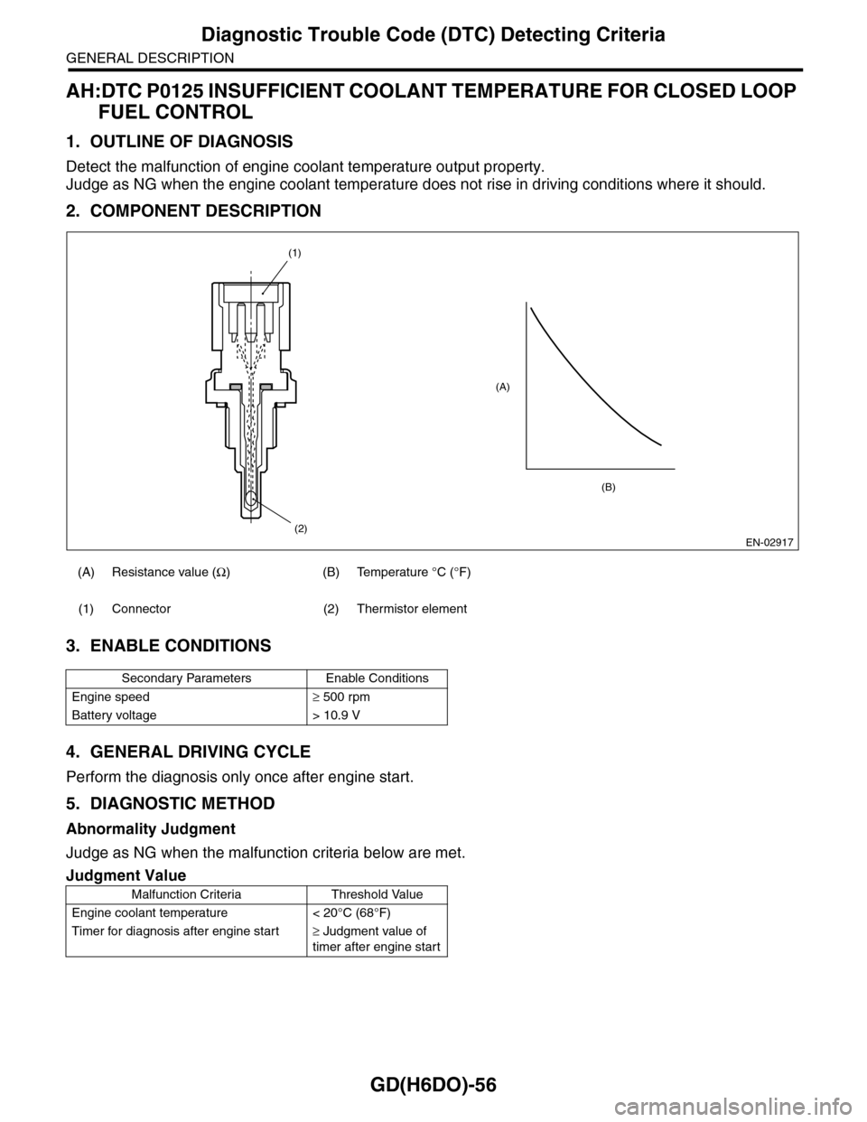
2. COMPONENT DESCRIPTION
3. ENABLE CONDITIONS
4. GENERAL DRIVING CYCLE
Perform the diagnosis only once after engine start.
5. DIAGNOSTIC METHOD
Abnormality Judgment
Judge as NG when the malfunction criteria below are met.
(A) Resistance value (Ω) (B) Temperature °C (°F)
(1) Connector (2) Thermistor element
Secondary Parameters Enable Conditions
Engine speed≥ 500 rpm
Battery voltage > 10.9 V
Judgment Value
Malfunction Criteria Threshold Value
Engine coolant temperature < 20°C (68°F)
Timer for diagnosis after engine star t≥ Judgment value of
timer after engine start
EN-02917
(A)
(2)
(1)
(B)
Page 1669 of 2453
GD(H6DO)-57
Diagnostic Trouble Code (DTC) Detecting Criteria
GENERAL DESCRIPTION
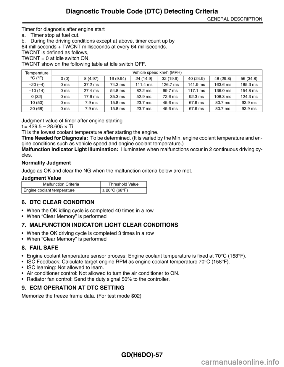
Timer for diagnosis after engine start
a. Timer stop at fuel cut.
b. During the driving conditions except a) above, timer count up by
64 milliseconds + TWCNT milliseconds at every 64 milliseconds.
TWCNT is defined as follows,
TWCNT = 0 at idle switch ON,
TWCNT show on the following table at idle switch OFF.
Judgment value of timer after engine starting
t = 429.5 – 28.605 × Ti
Ti is the lowest coolant temperature after starting the engine.
Time Needed for Diagnosis: To be determined. (It is varied by the Min. engine coolant temperature and en-
gine conditions such as vehicle speed and engine coolant temperature.)
Malfunction Indicator Light Illumination: Illuminates when malfunctions occur in 2 continuous driving cy-
cles.
Normality Judgment
Judge as OK and clear the NG when the malfunction criteria below are met.
6. DTC CLEAR CONDITION
•When the OK idling cycle is completed 40 times in a row
•When “Clear Memory” is performed
7. MALFUNCTION INDICATOR LIGHT CLEAR CONDITIONS
•When the OK driving cycle is completed 3 times in a row
•When “Clear Memory” is performed
8. FAIL SAFE
•Engine coolant temperature sensor process: Engine coolant temperature is fixed at 70°C (158°F).
•ISC Feedback: Calculate target engine RPM as engine coolant temperature 70°C (158°F).
•ISC learning: Not allowed to learn.
•Air conditioner control: Not allowed to turn the air conditioner to ON.
•Radiator fan control: Send the duty signal 50% to the controller.
9. ECM OPERATION AT DTC SETTING
Memorize the freeze frame data. (For test mode $02)
Te m p e r a t u r e
°C (°F)
Ve h i c l e s p e e d k m / h ( M P H )
0 (0) 8 (4.97) 16 (9.94) 24 (14.9) 32 (19.9) 40 (24.9) 48 (29.8) 56 (34.8)
–20 (–4) 0 ms 37.2 ms 74.3 ms 111.4 ms 126.7 ms 141.9 ms 163.6 ms 185.3 ms
–10 (14) 0 ms 27.4 ms 54.8 ms 82.2 ms 99.7 ms 117.1 ms 136.0 ms 154.8 ms
0 (32) 0 ms 17.6 ms 35.3 ms 52.9 ms 72.6 ms 92.3 ms 108.3 ms 124.3 ms
10 (50) 0 ms 7.9 ms 15.8 ms 23.7 ms 45.6 ms 67.6 ms 80.7 ms 93.9 ms
20 (68) 0 ms 7.9 ms 15.8 ms 23.7 ms 45.6 ms 67.6 ms 80.7 ms 93.9 ms
Judgment Value
Malfunction Criteria Threshold Value
Engine coolant temperature≥ 20°C (68°F)
Page 1670 of 2453
GD(H6DO)-58
Diagnostic Trouble Code (DTC) Detecting Criteria
GENERAL DESCRIPTION
AI: DTC P0126 INSUFFICIENT COOLANT TEMPERATURE FOR STABLE OPER-
ATION
1. OUTLINE OF DIAGNOSIS
Detect the malfunction of engine coolant temperature sensor characteristics.
The engine coolant temperature and fuel temperature is stored in memory from the last time that the engine
was stopped. If the engine coolant temperature does not decrease when it is expected to after starting the
engine, it is judged to be NG.
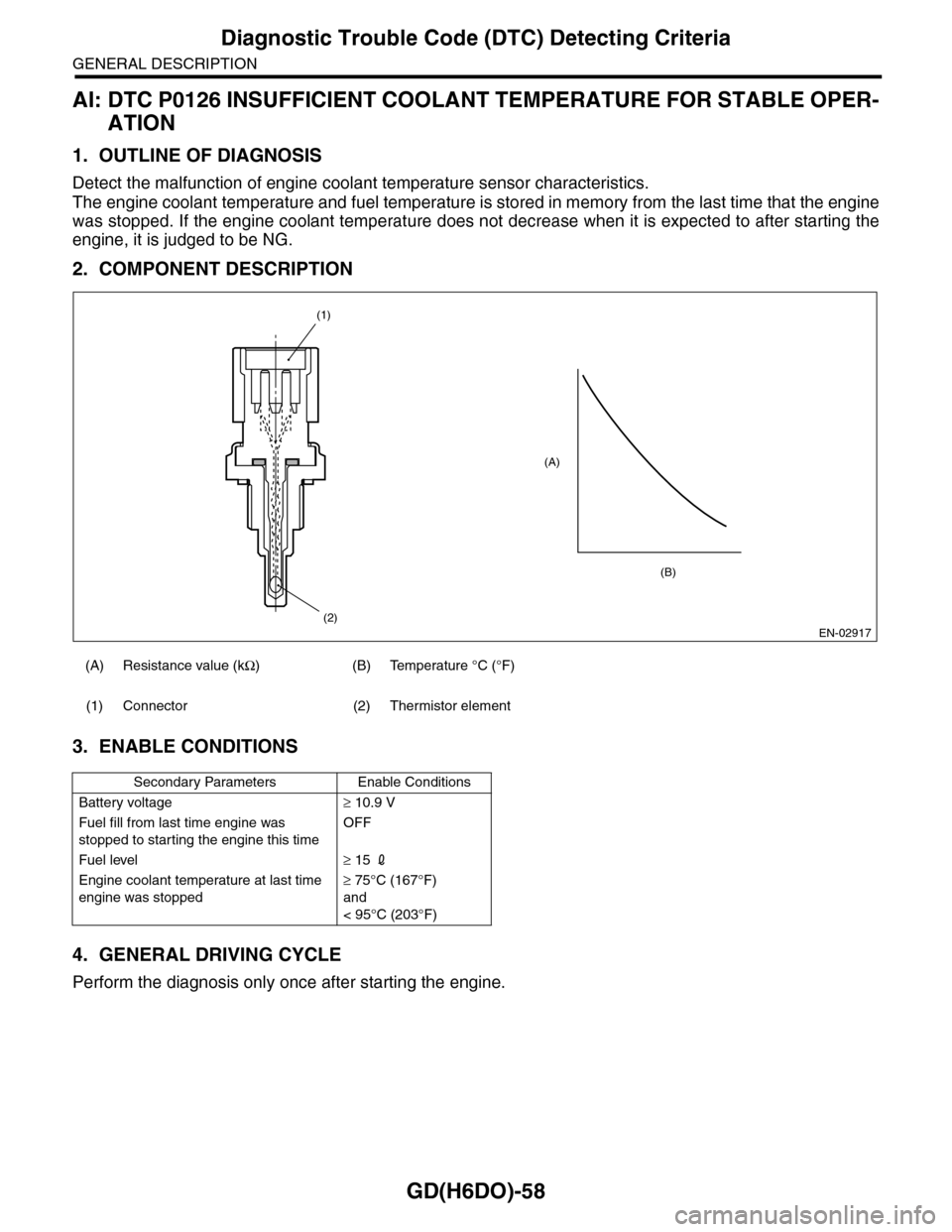
2. COMPONENT DESCRIPTION
3. ENABLE CONDITIONS
4. GENERAL DRIVING CYCLE
Perform the diagnosis only once after starting the engine.
(A) Resistance value (kΩ)(B)Temperature °C (°F)
(1) Connector (2) Thermistor element
Secondary Parameters Enable Conditions
Battery voltage≥ 10.9 V
Fuel fill from last time engine was
stopped to starting the engine this time
OFF
Fuel level≥ 15 2
Engine coolant temperature at last time
engine was stopped
≥ 75°C (167°F)
and
< 95°C (203°F)
EN-02917
(A)
(2)
(1)
(B)
Page 1671 of 2453
GD(H6DO)-59
Diagnostic Trouble Code (DTC) Detecting Criteria
GENERAL DESCRIPTION
5. DIAGNOSTIC METHOD
Abnormality Judgment
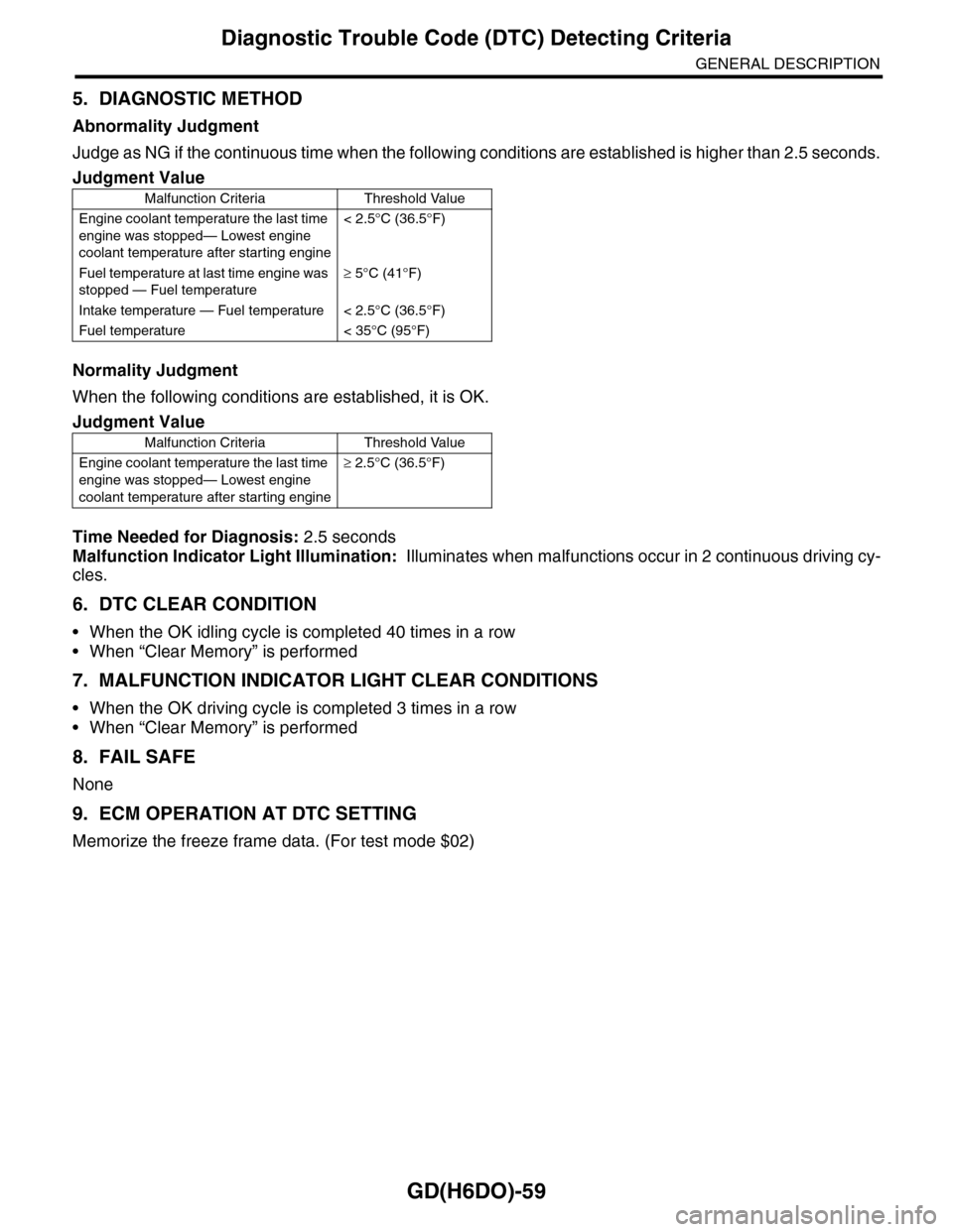
Judge as NG if the continuous time when the following conditions are established is higher than 2.5 seconds.
Normality Judgment
When the following conditions are established, it is OK.
Time Needed for Diagnosis: 2.5 seconds
Malfunction Indicator Light Illumination: Illuminates when malfunctions occur in 2 continuous driving cy-
cles.
6. DTC CLEAR CONDITION
•When the OK idling cycle is completed 40 times in a row
•When “Clear Memory” is performed
7. MALFUNCTION INDICATOR LIGHT CLEAR CONDITIONS
•When the OK driving cycle is completed 3 times in a row
•When “Clear Memory” is performed
8. FAIL SAFE
None
9. ECM OPERATION AT DTC SETTING
Memorize the freeze frame data. (For test mode $02)
Judgment Value
Malfunction Criteria Threshold Value
Engine coolant temperature the last time
engine was stopped— Lowest engine
coolant temperature after starting engine
< 2.5°C (36.5°F)
Fuel temperature at last time engine was
stopped — Fuel temperature
≥ 5°C (41°F)
Intake temperature — Fuel temperature < 2.5°C (36.5°F)
Fuel temperature < 35°C (95°F)
Judgment Value
Malfunction Criteria Threshold Value
Engine coolant temperature the last time
engine was stopped— Lowest engine
coolant temperature after starting engine
≥ 2.5°C (36.5°F)
Page 1674 of 2453
GD(H6DO)-62
Diagnostic Trouble Code (DTC) Detecting Criteria
GENERAL DESCRIPTION
AK:DTC P0131 O2 SENSOR CIRCUIT LOW VOLTAGE (BANK 1 SENSOR 1)
1. OUTLINE OF DIAGNOSIS
Detect the open or short circuit of sensor.
Judge as NG when the element impressed voltage is out of range, or the element current is out of range.
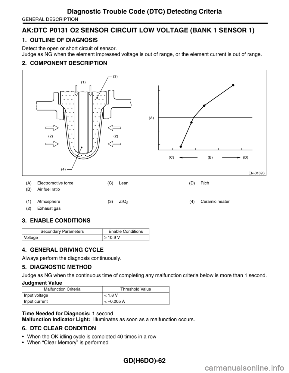
2. COMPONENT DESCRIPTION
3. ENABLE CONDITIONS
4. GENERAL DRIVING CYCLE
Always perform the diagnosis continuously.
5. DIAGNOSTIC METHOD
Judge as NG when the continuous time of completing any malfunction criteria below is more than 1 second.
Time Needed for Diagnosis: 1 second
Malfunction Indicator Light: Illuminates as soon as a malfunction occurs.
6. DTC CLEAR CONDITION
•When the OK idling cycle is completed 40 times in a row
•When “Clear Memory” is performed
(A) Electromotive force (C) Lean (D) Rich
(B) Air fuel ratio
(1) Atmosphere (3) ZrO2(4) Ceramic heater
(2) Exhaust gas
Secondary Parameters Enable Conditions
Vo l t a g e≥ 10.9 V
Judgment Value
Malfunction Criteria Threshold Value
Input voltage < 1.8 V
Input current < –0.005 A
(1)
(2)
(4)
(2)
(3)
EN-01693
(C) (B) (D)
(A)