2009 SUBARU TRIBECA engine oil
[x] Cancel search: engine oilPage 2046 of 2453
5AT-30
Stall Test
AUTOMATIC TRANSMISSION
5. Stall Test
A: INSPECTION
NOTE:
The stall test is extremely important in diagnosing
the condition of an automatic transmission and en-
gine. It should be conducted to measure the engine
stall speeds in “R” and “2nd of manual mode”.
Purposes of the stall test:
•Operational check of the automatic transmission
clutch
•Operational check of the torque converter clutch
•Engine performance check
1) Check that the throttle valve fully opens.
2) Check that the engine oil level is correct.
3) Check that the coolant level is correct.
4) Check that the ATF level is correct.
5) Check that the differential gear oil level is cor-
rect.
6) Raise the ATF temperature to 70 to 80°C (158 to
176°F) by driving a distance of 5 to 10 km (3 to 6
miles). Confirm the ATF temperature on Subaru
Select Monitor.
tor.>
7) Place the wheel chocks at the front and rear of
all wheels and apply the parking brake.
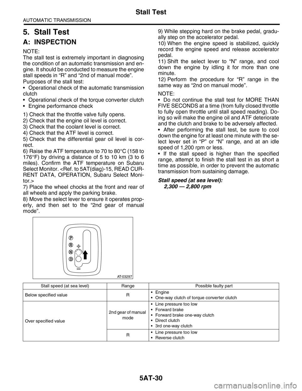
8) Move the select lever to ensure it operates prop-
erly, and then set to the “2nd gear of manual
mode”.
9) While stepping hard on the brake pedal, gradu-
ally step on the accelerator pedal.
10) When the engine speed is stabilized, quickly
record the engine speed and release accelerator
pedal.
11) Shift the select lever to “N” range, and cool
down the engine by idling it for more than one
minute.
12) Perform the procedure for “R” range in the
same way as “2nd on manual mode”.
NOTE:
•Do not continue the stall test for MORE THAN
FIVE SECONDS at a time (from fully closed throttle
to fully open throttle until stall speed reading). Do-
ing so will make the engine oil and ATF deteriorate
and the clutch and brake to be adversely affected.
•After performing the stall test, be sure to cool
down the engine for at least one minute with the se-
lect lever set in “P” or “N” range, and at an idle
speed of 1,200 rpm or less.
•If the stall speed is higher than the specified
range, attempt to finish the stall test in as short a
time as possible, in order to prevent the automatic
transmission from sustaining damage.
Stall speed (at sea level):
2,300 — 2,800 rpm
AT-03297
Stall speed (at sea level) Range Possible faulty part
Below specified value R•Engine
•One-way clutch of torque converter clutch
Over specified value
2nd gear of manual
mode
•Line pressure too low
•Forward brake
•Forward brake one-way clutch
•Direct clutch
•3rd one-way clutch
R•Line pressure too low
•Reverse clutch
Page 2048 of 2453
5AT-32
Line Pressure Test
AUTOMATIC TRANSMISSION
7. Line Pressure Test
A: MEASUREMENT
NOTE:
If the clutch or brake shows a sign of slippage, or
shifting interval is not correct, check the line pres-
sure.
•Excessive shock during up-shift may be due to
the line pressure being too high.
•Slippage or inability to operate the vehicle may,
in most cases, be due to loss of oil pressure for the
operation of clutch, brake or control valve.
1) Set the vehicle on a lift.
2) Remove the under cover.
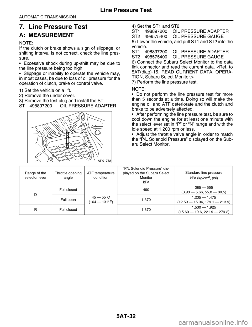
3) Remove the test plug and install the ST.
ST 498897200 OIL PRESSURE ADAPTER
4) Set the ST1 and ST2.
ST1 498897200 OIL PRESSURE ADAPTER
ST2 498575400 OIL PRESSURE GAUGE
5) Lower the vehicle, and pull ST1 and ST2 into the
vehicle.
ST1 498897200 OIL PRESSURE ADAPTER
ST2 498575400 OIL PRESSURE GAUGE
6) Connect the Subaru Select Monitor to the data
link connector and read the current data.
TION, Subaru Select Monitor.>
7) Perform the line pressure test.
NOTE:
•Do not perform the line pressure test for more
than 5 seconds at a time. Doing so will make the
engine oil and ATF deteriorate and the clutch and
brake to be adversely affected.
•After performing the line pressure test, be sure to
cool down the engine for at least one minute with
the select lever set in “P” or “N” range and with the
idle speed at 1,200 rpm or less.
•Adjust the throttle valve angle in order to match
the “P/L Solenoid Pressure” displayed on the Sub-
aru Select Monitor.
AT-01752
Range of the
selector lever
Throttle opening
angle
AT F t e m p e r a t u r e
condition
“P/L Solenoid Pressure” dis-
played on the Subaru Select
Monitor
kPa
Standard line pressure
kPa (kg/cm2, psi)
D
Full closed
45 — 55°C
(104 — 131°F)
490385 — 555
(3.93 — 5.66, 55.8 — 80.5)
Full open 1,3701,235 — 1,475
(12.59 — 15.04, 179.1 — 213.9)
RFull closed 1,3701,530 — 1,925
(15.60 — 19.6, 221.9 — 279.2)
Page 2049 of 2453
5AT-33
Transfer Clutch Pressure Test
AUTOMATIC TRANSMISSION
8. Transfer Clutch Pressure
Test
A: INSPECTION
1) Lift-up the vehicle.
2) Remove the bolts holding the heat shield cover,
and move the heat shield cover to the rear.
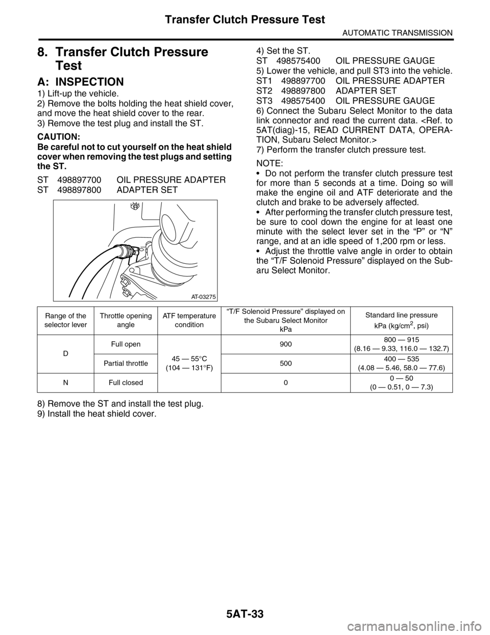
3) Remove the test plug and install the ST.
CAUTION:
Be careful not to cut yourself on the heat shield
cover when removing the test plugs and setting
the ST.
ST 498897700 OIL PRESSURE ADAPTER
ST 498897800 ADAPTER SET
4) Set the ST.
ST 498575400 OIL PRESSURE GAUGE
5) Lower the vehicle, and pull ST3 into the vehicle.
ST1 498897700 OIL PRESSURE ADAPTER
ST2 498897800 ADAPTER SET
ST3 498575400 OIL PRESSURE GAUGE
6) Connect the Subaru Select Monitor to the data
link connector and read the current data.
TION, Subaru Select Monitor.>
7) Perform the transfer clutch pressure test.
NOTE:
•Do not perform the transfer clutch pressure test
for more than 5 seconds at a time. Doing so will
make the engine oil and ATF deteriorate and the
clutch and brake to be adversely affected.
•After performing the transfer clutch pressure test,
be sure to cool down the engine for at least one
minute with the select lever set in the “P” or “N”
range, and at an idle speed of 1,200 rpm or less.
•Adjust the throttle valve angle in order to obtain
the “T/F Solenoid Pressure” displayed on the Sub-
aru Select Monitor.
8) Remove the ST and install the test plug.
9) Install the heat shield cover.
AT-03275
Range of the
selector lever
Throttle opening
angle
AT F t e m p e r a t u r e
condition
“T/F Solenoid Pressure” displayed on
the Subaru Select Monitor
kPa
Standard line pressure
kPa (kg/cm2, psi)
D
Full open
45 — 55°C
(104 — 131°F)
900800 — 915
(8.16 — 9.33, 116.0 — 132.7)
Par tial throttle 500400 — 535
(4.08 — 5.46, 58.0 — 77.6)
NFull closed 00 — 50
(0 — 0.51, 0 — 7.3)
Page 2051 of 2453
5AT-35
Automatic Transmission Assembly
AUTOMATIC TRANSMISSION
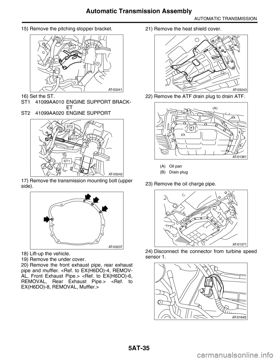
15) Remove the pitching stopper bracket.
16) Set the ST.
ST1 41099AA010 ENGINE SUPPORT BRACK-
ET
ST2 41099AA020 ENGINE SUPPORT
17) Remove the transmission mounting bolt (upper
side).
18) Lift-up the vehicle.
19) Remove the under cover.
20) Remove the front exhaust pipe, rear exhaust
pipe and muffler.
21) Remove the heat shield cover.
22) Remove the ATF drain plug to drain ATF.
23) Remove the oil charge pipe.
24) Disconnect the connector from turbine speed
sensor 1.
AT-03241
AT-03242
ST2
ST1
AT-03237
(A) Oil pan
(B) Drain plug
AT-03243
(A)
AT-01361
(B)
AT-01371
AT-01642
Page 2056 of 2453
5AT-40
Automatic Transmission Assembly
AUTOMATIC TRANSMISSION
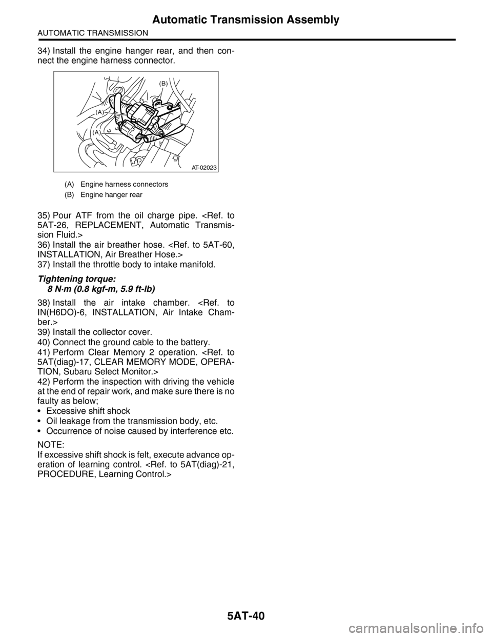
34) Install the engine hanger rear, and then con-
nect the engine harness connector.
35) Pour ATF from the oil charge pipe.
sion Fluid.>
36) Install the air breather hose.
37) Install the throttle body to intake manifold.
Tightening torque:
8 N·m (0.8 kgf-m, 5.9 ft-lb)
38) Install the air intake chamber.
ber.>
39) Install the collector cover.
40) Connect the ground cable to the battery.
41) Perform Clear Memory 2 operation.
TION, Subaru Select Monitor.>
42) Perform the inspection with driving the vehicle
at the end of repair work, and make sure there is no
faulty as below;
•Excessive shift shock
•Oil leakage from the transmission body, etc.
•Occurrence of noise caused by interference etc.
NOTE:
If excessive shift shock is felt, execute advance op-
eration of learning control.
(A) Engine harness connectors
(B) Engine hanger rear
(B)
(A)
(A)
AT-02023
Page 2128 of 2453
5AT(diag)-11
Transmission Control Module (TCM) I/O Signal
AUTOMATIC TRANSMISSION (DIAGNOSTICS)
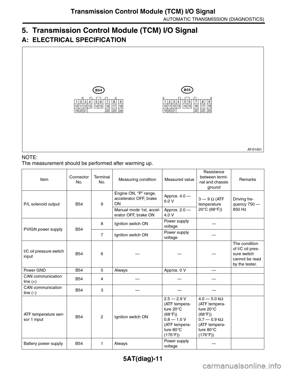
5. Transmission Control Module (TCM) I/O Signal
A: ELECTRICAL SPECIFICATION
NOTE:
The measurement should be performed after warming up.
ItemConnector
No.
Te r m i n a l
No.Measuring condition Measured value
Resistance
between termi-
nal and chassis
ground
Remarks
P/L solenoid output B54 9
Engine ON, “P” range,
accelerator OFF, brake
ON
Approx. 4.0 —
6.0 V3 — 9 Ω (ATF
temperature
20°C (68°F))
Driving fre-
quency 750 —
850 HzManual mode 1st, accel-
erator OFF, brake ON
Approx. 2.0 —
4.0 V
PVIGN power supply B54
8Ignition switch ONPow er s up p ly
voltage—
7Ignition switch ONPow er s up p ly
voltage—
I/C oil pressure switch
inputB54 6 — — —
The condition
of I/C oil pres-
sure switch
cannot be read
by the tester.
Pow er G N D B 5 4 5 A lways A pp r ox . 0 V —
CAN communication
line (+)B54 4 — — —
CAN communication
line (–)B54 3 — — —
AT F t e m p e r a t u r e s e n -
sor 1 inputB54 2 Ignition switch ON
2.5 — 2.9 V
(ATF tempera-
ture 20°C
(68°F))
0.8 — 1.0 V
(ATF tempera-
ture 80°C
(176°F))
4.0 — 5.0 kΩ
(ATF tempera-
ture 20°C
(68°F))
0.7 — 0.9 kΩ
(ATF tempera-
ture 80°C
(176°F))
Battery power supply B54 1 AlwaysPow er s up p ly
voltage—
AT-01451
12341011 121920 21135614 1578916 17 1822 23 24
12789563410 11 1219 20 2113 14 15 16 17 18222324
B55B54
Page 2130 of 2453
5AT(diag)-13
Transmission Control Module (TCM) I/O Signal
AUTOMATIC TRANSMISSION (DIAGNOSTICS)
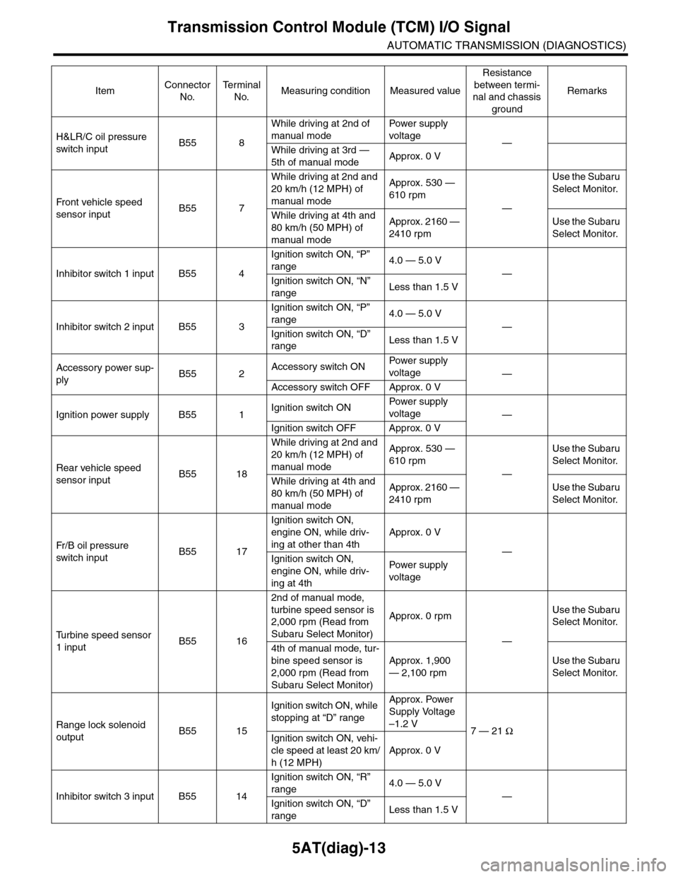
H&LR/C oil pressure
switch inputB55 8
While driving at 2nd of
manual mode
Pow er s up p ly
voltage—
While driving at 3rd —
5th of manual modeApprox. 0 V
Fr o nt veh ic l e sp e ed
sensor inputB55 7
While driving at 2nd and
20 km/h (12 MPH) of
manual mode
Approx. 530 —
610 rpm
—
Use the Subaru
Select Monitor.
While driving at 4th and
80 km/h (50 MPH) of
manual mode
Approx. 2160 —
2410 rpm
Use the Subaru
Select Monitor.
Inhibitor switch 1 input B55 4
Ignition switch ON, “P”
range4.0 — 5.0 V
—
Ignition switch ON, “N”
rangeLess than 1.5 V
Inhibitor switch 2 input B55 3
Ignition switch ON, “P”
range4.0 — 5.0 V
—
Ignition switch ON, “D”
rangeLess than 1.5 V
Accessory power sup-
plyB55 2Accessory switch ONPow er s up p ly
voltage—
Accessory switch OFF Approx. 0 V
Ignition power supply B55 1Ignition switch ONPow er s up p ly
voltage—
Ignition switch OFF Approx. 0 V
Rear vehicle speed
sensor inputB55 18
While driving at 2nd and
20 km/h (12 MPH) of
manual mode
Approx. 530 —
610 rpm
—
Use the Subaru
Select Monitor.
While driving at 4th and
80 km/h (50 MPH) of
manual mode
Approx. 2160 —
2410 rpm
Use the Subaru
Select Monitor.
Fr / B oi l p r e ssu r e
switch inputB55 17
Ignition switch ON,
engine ON, while driv-
ing at other than 4th
Approx. 0 V
—
Ignition switch ON,
engine ON, while driv-
ing at 4th
Pow er s up p ly
voltage
Tu r b i n e s p e e d s e n s o r
1 inputB55 16
2nd of manual mode,
turbine speed sensor is
2,000 rpm (Read from
Subaru Select Monitor)
Approx. 0 rpm
—
Use the Subaru
Select Monitor.
4th of manual mode, tur-
bine speed sensor is
2,000 rpm (Read from
Subaru Select Monitor)
Approx. 1,900
— 2,100 rpm
Use the Subaru
Select Monitor.
Range lock solenoid
outputB55 15
Ignition switch ON, while
stopping at “D” range
Approx. Power
Supply Voltage
–1.2 V7 — 21 Ω
Ignition switch ON, vehi-
cle speed at least 20 km/
h (12 MPH)
Approx. 0 V
Inhibitor switch 3 input B55 14
Ignition switch ON, “R”
range4.0 — 5.0 V
—
Ignition switch ON, “D”
rangeLess than 1.5 V
ItemConnector
No.
Te r m i n a l
No.Measuring condition Measured value
Resistance
between termi-
nal and chassis
ground
Remarks
Page 2133 of 2453
5AT(diag)-16
Subaru Select Monitor
AUTOMATIC TRANSMISSION (DIAGNOSTICS)
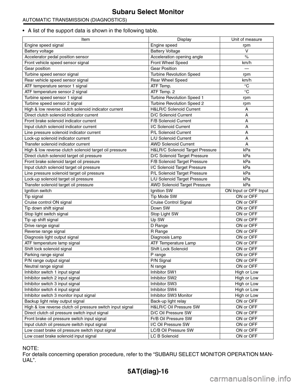
•A list of the support data is shown in the following table.
NOTE:
For details concerning operation procedure, refer to the “SUBARU SELECT MONITOR OPERATION MAN-
UAL”.
Item Display Unit of measure
Engine speed signal Engine speed rpm
Battery voltage Battery Voltage V
Accelerator pedal position sensor Acceleration opening angle %
Fr o nt veh ic l e sp e ed se n so r s ig n al Fr o n t W h ee l S p e ed km/ h
Gear position Gear Position —
Tu r b i n e s p e e d s e n s o r s i g n a l Tu r b i n e R e v o l u t i o n S p e e d r p m
Rear vehicle speed sensor signal Rear Wheel Speed km/h
ATF temperature sensor 1 signal ATF Temp. °C
ATF temperature sensor 2 signal ATF Temp. 2 °C
Tu r b i n e s p e e d s e n s o r 1 s i g n a l Tu r b i n e R e v o l u t i o n S p e e d 1 r p m
Tu r b i n e s p e e d s e n s o r 2 s i g n a l Tu r b i n e R e v o l u t i o n S p e e d 2 r p m
High & low reverse clutch solenoid indicator current H&LR/C Solenoid Current A
Direct clutch solenoid indicator current D/C Solenoid Current A
Fr o nt b rake so l en oi d in di c at o r c u rr e n t F / B S o l en o id Cur r e nt A
Input clutch solenoid indicator current I/C Solenoid Current A
Line pressure solenoid indicator current P/L Solenoid Current A
Lock-up solenoid indicator current L/U Solenoid Current A
Tr a n s f e r s o l e n o i d i n d i c a t o r c u r r e n t A W D S o l e n o i d C u r r e n t A
High & low reverse clutch solenoid target oil pressure H&LR/C Solenoid Target Pressure kPa
Direct clutch solenoid target oil pressure D/C Solenoid Target Pressure kPa
Fr o nt b rake so l en oi d ta r g et o il pr e ss ur e F / B S o l en o id Ta r g et P r es su r e kPa
Input clutch solenoid target oil pressure I/C Solenoid Target Pressure kPa
Line pressure solenoid target oil pressure P/L Solenoid Target Pressure kPa
Lock-up solenoid target oil pressure L/U Solenoid Target Pressure kPa
Tr a n s f e r s o l e n o i d t a r g e t o i l p r e s s u r e A W D S o l e n o i d Ta r g e t P r e s s u r e k P a
Ignition switch Ignition SW ON Input or OFF Input
Tip signal Tip Mode SW ON or OFF
Cruise control ON signal Cruise Control Signal ON or OFF
Tip down shift signal Down SW ON or OFF
Stop light switch signal Stop Light SW ON or OFF
Tip up shift signal Up SW ON or OFF
Drive range signal D Range ON or OFF
Reverse range signal R Range ON or OFF
Diagnosis light output signal Diagnosis Lamp ON or OFF
AT F t e m p e r a t u r e l a m p s i g n a l AT F Te m p e r a t u r e L a m p O N o r O F F
Shift lock solenoid signal Shift Lock Solenoid ON or OFF
Par king range signal P range ON or OFF
P/N range output signal P/N Signal ON or OFF
Neutral range signal N range ON or OFF
Inhibitor switch 1 input signal Inhibitor SW1 High or Low
Inhibitor switch 2 input signal Inhibitor SW2 High or Low
Inhibitor switch 3 input signal Inhibitor SW3 High or Low
Inhibitor switch 4 input signal Inhibitor SW4 High or Low
Inhibitor switch 3 monitor input signal Inhibitor SW3 Monitor High or Low
Backup light relay output signal Back-up light relay ON or OFF
High & low reverse clutch oil pressure switch input signal H&LR/C Oil Pressure SW ON or OFF
Direct clutch oil pressure switch input signal D/C Oil Pressure SW ON or OFF
Fr o nt b rake oi l pr e ss ur e swi tc h i n pu t si gn a l Fr / B Oi l P r e ss ur e S W ON or OF F
Input clutch oil pressure switch input signal I/C Oil Pressure SW ON or OFF
Low coast brake oil pressure switch input signal LC/B Oil Pressure SW ON or OFF
Low coast brake solenoid input signal LC B Solenoid ON or OFF