Page 2150 of 2453
5AT(diag)-33
Diagnostic Procedure with Diagnostic Trouble Code (DTC)
AUTOMATIC TRANSMISSION (DIAGNOSTICS)
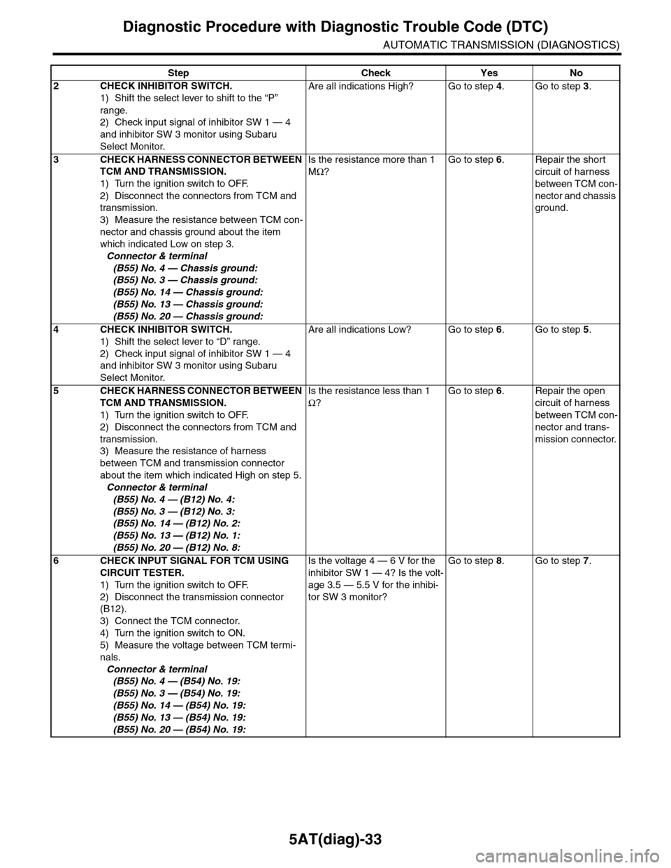
2CHECK INHIBITOR SWITCH.
1) Shift the select lever to shift to the “P”
range.
2) Check input signal of inhibitor SW 1 — 4
and inhibitor SW 3 monitor using Subaru
Select Monitor.
Are all indications High? Go to step 4.Go to step 3.
3CHECK HARNESS CONNECTOR BETWEEN
TCM AND TRANSMISSION.
1) Turn the ignition switch to OFF.
2) Disconnect the connectors from TCM and
transmission.
3) Measure the resistance between TCM con-
nector and chassis ground about the item
which indicated Low on step 3.
Connector & terminal
(B55) No. 4 — Chassis ground:
(B55) No. 3 — Chassis ground:
(B55) No. 14 — Chassis ground:
(B55) No. 13 — Chassis ground:
(B55) No. 20 — Chassis ground:
Is the resistance more than 1
MΩ?
Go to step 6.Repair the short
circuit of harness
between TCM con-
nector and chassis
ground.
4CHECK INHIBITOR SWITCH.
1) Shift the select lever to “D” range.
2) Check input signal of inhibitor SW 1 — 4
and inhibitor SW 3 monitor using Subaru
Select Monitor.
Are all indications Low? Go to step 6.Go to step 5.
5CHECK HARNESS CONNECTOR BETWEEN
TCM AND TRANSMISSION.
1) Turn the ignition switch to OFF.
2) Disconnect the connectors from TCM and
transmission.
3) Measure the resistance of harness
between TCM and transmission connector
about the item which indicated High on step 5.
Connector & terminal
(B55) No. 4 — (B12) No. 4:
(B55) No. 3 — (B12) No. 3:
(B55) No. 14 — (B12) No. 2:
(B55) No. 13 — (B12) No. 1:
(B55) No. 20 — (B12) No. 8:
Is the resistance less than 1
Ω?
Go to step 6.Repair the open
circuit of harness
between TCM con-
nector and trans-
mission connector.
6CHECK INPUT SIGNAL FOR TCM USING
CIRCUIT TESTER.
1) Turn the ignition switch to OFF.
2) Disconnect the transmission connector
(B12).
3) Connect the TCM connector.
4) Turn the ignition switch to ON.
5) Measure the voltage between TCM termi-
nals.
Connector & terminal
(B55) No. 4 — (B54) No. 19:
(B55) No. 3 — (B54) No. 19:
(B55) No. 14 — (B54) No. 19:
(B55) No. 13 — (B54) No. 19:
(B55) No. 20 — (B54) No. 19:
Is the voltage 4 — 6 V for the
inhibitor SW 1 — 4? Is the volt-
age 3.5 — 5.5 V for the inhibi-
tor SW 3 monitor?
Go to step 8.Go to step 7.
Step Check Yes No
Page 2151 of 2453
5AT(diag)-34
Diagnostic Procedure with Diagnostic Trouble Code (DTC)
AUTOMATIC TRANSMISSION (DIAGNOSTICS)
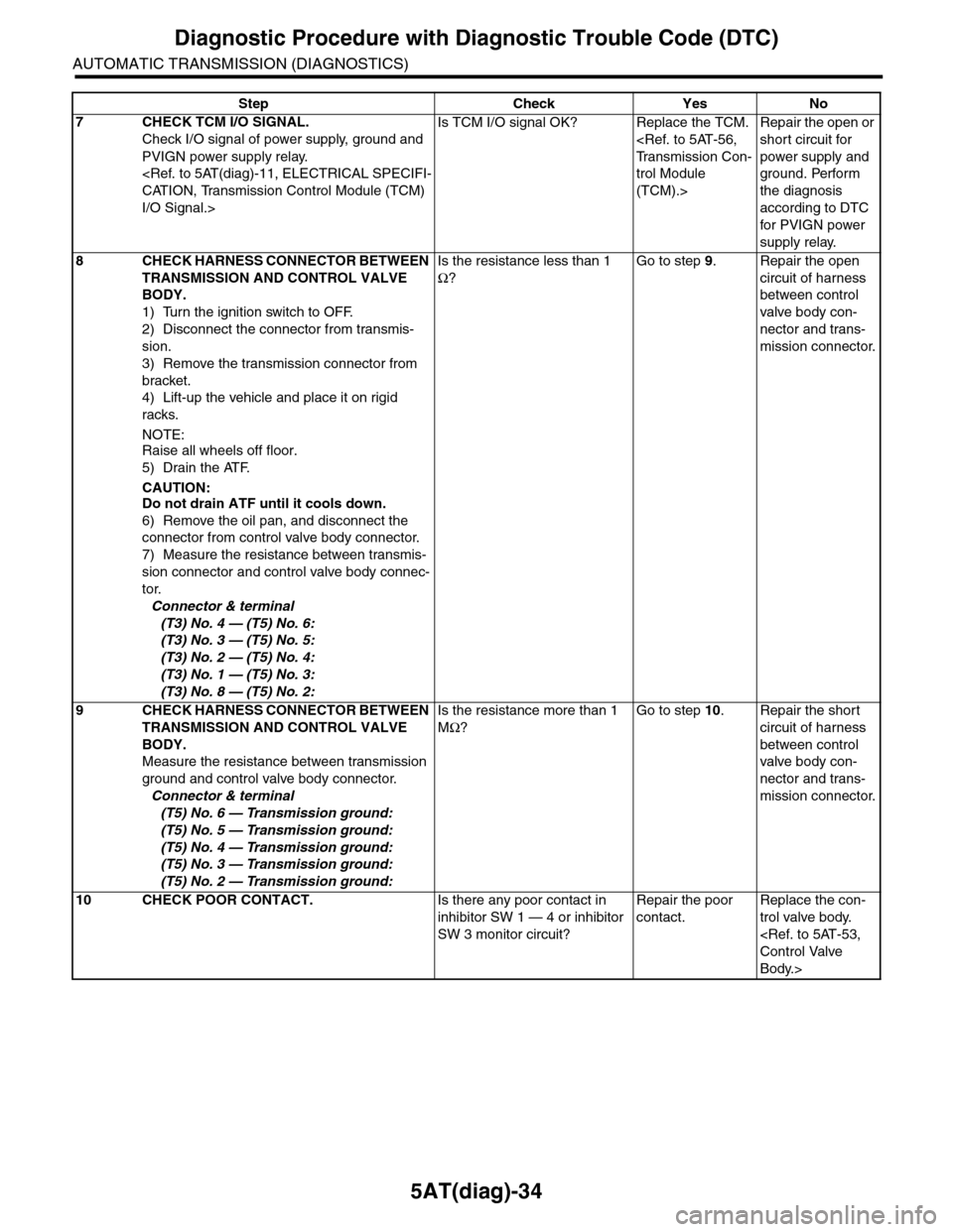
7CHECK TCM I/O SIGNAL.
Check I/O signal of power supply, ground and
PVIGN power supply relay.
CATION, Transmission Control Module (TCM)
I/O Signal.>
Is TCM I/O signal OK? Replace the TCM.
Tr a n s m i s s i o n C o n -
trol Module
(TCM).>
Repair the open or
short circuit for
power supply and
ground. Perform
the diagnosis
according to DTC
for PVIGN power
supply relay.
8CHECK HARNESS CONNECTOR BETWEEN
TRANSMISSION AND CONTROL VALVE
BODY.
1) Turn the ignition switch to OFF.
2) Disconnect the connector from transmis-
sion.
3) Remove the transmission connector from
bracket.
4) Lift-up the vehicle and place it on rigid
racks.
NOTE:
Raise all wheels off floor.
5) Drain the ATF.
CAUTION:Do not drain ATF until it cools down.
6) Remove the oil pan, and disconnect the
connector from control valve body connector.
7) Measure the resistance between transmis-
sion connector and control valve body connec-
tor.
Connector & terminal
(T3) No. 4 — (T5) No. 6:
(T3) No. 3 — (T5) No. 5:
(T3) No. 2 — (T5) No. 4:
(T3) No. 1 — (T5) No. 3:
(T3) No. 8 — (T5) No. 2:
Is the resistance less than 1
Ω?
Go to step 9.Repair the open
circuit of harness
between control
valve body con-
nector and trans-
mission connector.
9CHECK HARNESS CONNECTOR BETWEEN
TRANSMISSION AND CONTROL VALVE
BODY.
Measure the resistance between transmission
ground and control valve body connector.
Connector & terminal
(T5) No. 6 — Transmission ground:
(T5) No. 5 — Transmission ground:
(T5) No. 4 — Transmission ground:
(T5) No. 3 — Transmission ground:
(T5) No. 2 — Transmission ground:
Is the resistance more than 1
MΩ?
Go to step 10.Repair the short
circuit of harness
between control
valve body con-
nector and trans-
mission connector.
10 CHECK POOR CONTACT.Is there any poor contact in
inhibitor SW 1 — 4 or inhibitor
SW 3 monitor circuit?
Repair the poor
contact.
Replace the con-
trol valve body.
Control Valve
Body.>
Step Check Yes No
Page 2152 of 2453
5AT(diag)-35
Diagnostic Procedure with Diagnostic Trouble Code (DTC)
AUTOMATIC TRANSMISSION (DIAGNOSTICS)
B: DTC P0712 TRANSMISSION FLUID TEMPERATURE SENSOR CIRCUIT LOW
INPUT
DTC DETECTING CONDITION:
Input signal circuit to ATF temperature sensor 1 is open.
TROUBLE SYMPTOM:
Excessive shift shock
WIRING DIAGRAM:
AT-02037
2
B54
B11
T4
T5
TCM
13
B54
B11
12789563410 11 1219 20 2113 14 15 16 17 18222324
TRANSMISSION
125678
131415169101112
34
17181920
512
161
123 68910 11 12 13 14451516
T5
7
Page 2153 of 2453
5AT(diag)-36
Diagnostic Procedure with Diagnostic Trouble Code (DTC)
AUTOMATIC TRANSMISSION (DIAGNOSTICS)
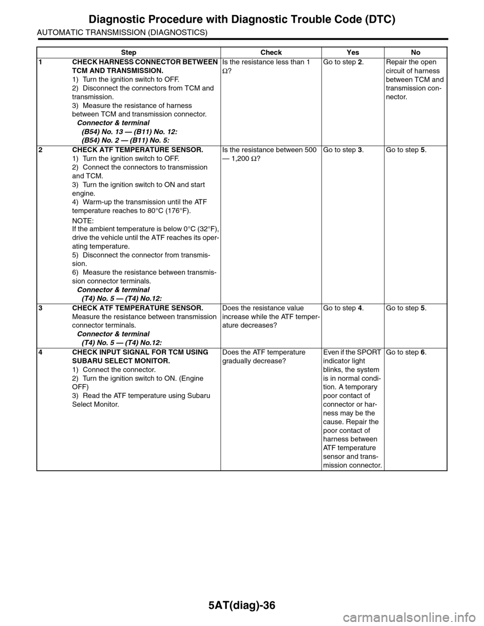
Step Check Yes No
1CHECK HARNESS CONNECTOR BETWEEN
TCM AND TRANSMISSION.
1) Turn the ignition switch to OFF.
2) Disconnect the connectors from TCM and
transmission.
3) Measure the resistance of harness
between TCM and transmission connector.
Connector & terminal
(B54) No. 13 — (B11) No. 12:
(B54) No. 2 — (B11) No. 5:
Is the resistance less than 1
Ω?
Go to step 2.Repair the open
circuit of harness
between TCM and
transmission con-
nector.
2CHECK ATF TEMPERATURE SENSOR.
1) Turn the ignition switch to OFF.
2) Connect the connectors to transmission
and TCM.
3) Turn the ignition switch to ON and start
engine.
4) Warm-up the transmission until the ATF
temperature reaches to 80°C (176°F).
NOTE:
If the ambient temperature is below 0°C (32°F),
drive the vehicle until the ATF reaches its oper-
ating temperature.
5) Disconnect the connector from transmis-
sion.
6) Measure the resistance between transmis-
sion connector terminals.
Connector & terminal
(T4) No. 5 — (T4) No.12:
Is the resistance between 500
— 1,200 Ω?
Go to step 3.Go to step 5.
3CHECK ATF TEMPERATURE SENSOR.
Measure the resistance between transmission
connector terminals.
Connector & terminal
(T4) No. 5 — (T4) No.12:
Does the resistance value
increase while the ATF temper-
ature decreases?
Go to step 4.Go to step 5.
4CHECK INPUT SIGNAL FOR TCM USING
SUBARU SELECT MONITOR.
1) Connect the connector.
2) Turn the ignition switch to ON. (Engine
OFF)
3) Read the ATF temperature using Subaru
Select Monitor.
Does the ATF temperature
gradually decrease?
Even if the SPORT
indicator light
blinks, the system
is in normal condi-
tion. A temporary
poor contact of
connector or har-
ness may be the
cause. Repair the
poor contact of
harness between
AT F t e m p e r a t u r e
sensor and trans-
mission connector.
Go to step 6.
Page 2154 of 2453
5AT(diag)-37
Diagnostic Procedure with Diagnostic Trouble Code (DTC)
AUTOMATIC TRANSMISSION (DIAGNOSTICS)
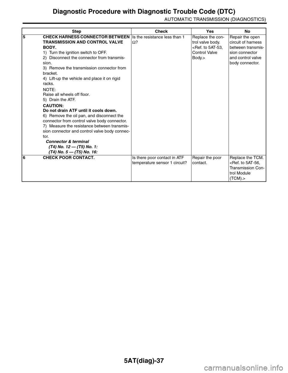
5CHECK HARNESS CONNECTOR BETWEEN
TRANSMISSION AND CONTROL VALVE
BODY.
1) Turn the ignition switch to OFF.
2) Disconnect the connector from transmis-
sion.
3) Remove the transmission connector from
bracket.
4) Lift-up the vehicle and place it on rigid
racks.
NOTE:Raise all wheels off floor.
5) Drain the ATF.
CAUTION:Do not drain ATF until it cools down.
6) Remove the oil pan, and disconnect the
connector from control valve body connector.
7) Measure the resistance between transmis-
sion connector and control valve body connec-
tor.
Connector & terminal
(T4) No. 12 — (T5) No. 1:
(T4) No. 5 — (T5) No. 16:
Is the resistance less than 1
Ω?
Replace the con-
trol valve body.
Control Valve
Body.>
Repair the open
circuit of harness
between transmis-
sion connector
and control valve
body connector.
6CHECK POOR CONTACT.Is there poor contact in ATF
temperature sensor 1 circuit?
Repair the poor
contact.
Replace the TCM.
Tr a n s m i s s i o n C o n -
trol Module
(TCM).>
Step Check Yes No
Page 2155 of 2453
5AT(diag)-38
Diagnostic Procedure with Diagnostic Trouble Code (DTC)
AUTOMATIC TRANSMISSION (DIAGNOSTICS)
C: DTC P0713 TRANSMISSION FLUID TEMPERATURE SENSOR CIRCUIT HIGH
INPUT
DTC DETECTING CONDITION:
Input signal circuit to ATF temperature sensor 1 is shorted.
TROUBLE SYMPTOM:
Excessive shift shock
WIRING DIAGRAM:
AT-02037
2
B54
B11
T4
T5
TCM
13
B54
B11
12789563410 11 1219 20 2113 14 15 16 17 18222324
TRANSMISSION
125678
131415169101112
34
17181920
512
161
123 68910 11 12 13 14451516
T5
7
Page 2156 of 2453
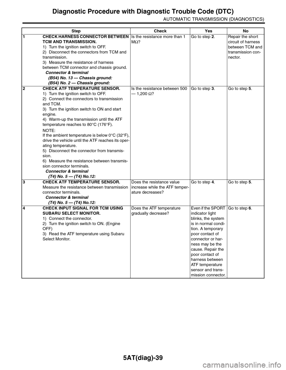
5AT(diag)-39
Diagnostic Procedure with Diagnostic Trouble Code (DTC)
AUTOMATIC TRANSMISSION (DIAGNOSTICS)
Step Check Yes No
1CHECK HARNESS CONNECTOR BETWEEN
TCM AND TRANSMISSION.
1) Turn the ignition switch to OFF.
2) Disconnect the connectors from TCM and
transmission.
3) Measure the resistance of harness
between TCM connector and chassis ground.
Connector & terminal
(B54) No. 13 — Chassis ground:
(B54) No. 2 — Chassis ground:
Is the resistance more than 1
MΩ?
Go to step 2.Repair the short
circuit of harness
between TCM and
transmission con-
nector.
2CHECK ATF TEMPERATURE SENSOR.
1) Turn the ignition switch to OFF.
2) Connect the connectors to transmission
and TCM.
3) Turn the ignition switch to ON and start
engine.
4) Warm-up the transmission until the ATF
temperature reaches to 80°C (176°F).
NOTE:
If the ambient temperature is below 0°C (32°F),
drive the vehicle until the ATF reaches its oper-
ating temperature.
5) Disconnect the connector from transmis-
sion.
6) Measure the resistance between transmis-
sion connector terminals.
Connector & terminal
(T4) No. 5 — (T4) No.12:
Is the resistance between 500
— 1,200 Ω?
Go to step 3.Go to step 5.
3CHECK ATF TEMPERATURE SENSOR.
Measure the resistance between transmission
connector terminals.
Connector & terminal
(T4) No. 5 — (T4) No.12:
Does the resistance value
increase while the ATF temper-
ature decreases?
Go to step 4.Go to step 5.
4CHECK INPUT SIGNAL FOR TCM USING
SUBARU SELECT MONITOR.
1) Connect the connector.
2) Turn the ignition switch to ON. (Engine
OFF)
3) Read the ATF temperature using Subaru
Select Monitor.
Does the ATF temperature
gradually decrease?
Even if the SPORT
indicator light
blinks, the system
is in normal condi-
tion. A temporary
poor contact of
connector or har-
ness may be the
cause. Repair the
poor contact of
harness between
AT F t e m p e r a t u r e
sensor and trans-
mission connector.
Go to step 6.
Page 2157 of 2453
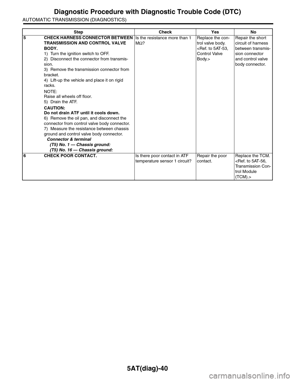
5AT(diag)-40
Diagnostic Procedure with Diagnostic Trouble Code (DTC)
AUTOMATIC TRANSMISSION (DIAGNOSTICS)
5CHECK HARNESS CONNECTOR BETWEEN
TRANSMISSION AND CONTROL VALVE
BODY.
1) Turn the ignition switch to OFF.
2) Disconnect the connector from transmis-
sion.
3) Remove the transmission connector from
bracket.
4) Lift-up the vehicle and place it on rigid
racks.
NOTE:Raise all wheels off floor.
5) Drain the ATF.
CAUTION:Do not drain ATF until it cools down.
6) Remove the oil pan, and disconnect the
connector from control valve body connector.
7) Measure the resistance between chassis
ground and control valve body connector.
Connector & terminal
(T5) No. 1 — Chassis ground:
(T5) No. 16 — Chassis ground:
Is the resistance more than 1
MΩ?
Replace the con-
trol valve body.
Control Valve
Body.>
Repair the short
circuit of harness
between transmis-
sion connector
and control valve
body connector.
6CHECK POOR CONTACT.Is there poor contact in ATF
temperature sensor 1 circuit?
Repair the poor
contact.
Replace the TCM.
Tr a n s m i s s i o n C o n -
trol Module
(TCM).>
Step Check Yes No