2009 SUBARU TRIBECA check oil
[x] Cancel search: check oilPage 1967 of 2453
SC(H6DO)-9
Starter
STARTING/CHARGING SYSTEMS
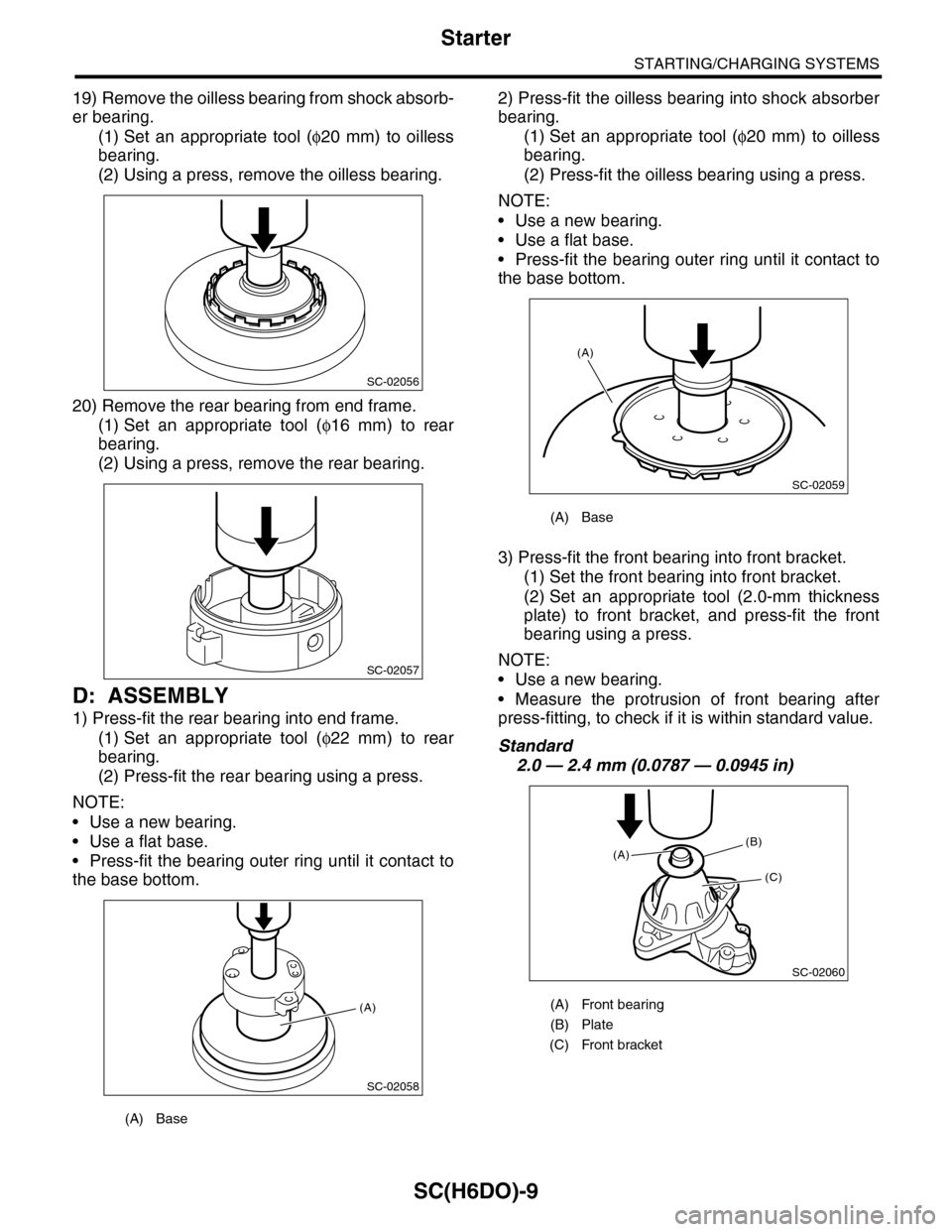
19) Remove the oilless bearing from shock absorb-
er bearing.
(1) Set an appropriate tool (φ20 mm) to oilless
bearing.
(2) Using a press, remove the oilless bearing.
20) Remove the rear bearing from end frame.
(1) Set an appropriate tool (φ16 mm) to rear
bearing.
(2) Using a press, remove the rear bearing.
D: ASSEMBLY
1) Press-fit the rear bearing into end frame.
(1) Set an appropriate tool (φ22 mm) to rear
bearing.
(2) Press-fit the rear bearing using a press.
NOTE:
•Use a new bearing.
•Use a flat base.
•Press-fit the bearing outer ring until it contact to
the base bottom.
2) Press-fit the oilless bearing into shock absorber
bearing.
(1) Set an appropriate tool (φ20 mm) to oilless
bearing.
(2) Press-fit the oilless bearing using a press.
NOTE:
•Use a new bearing.
•Use a flat base.
•Press-fit the bearing outer ring until it contact to
the base bottom.
3) Press-fit the front bearing into front bracket.
(1) Set the front bearing into front bracket.
(2) Set an appropriate tool (2.0-mm thickness
plate) to front bracket, and press-fit the front
bearing using a press.
NOTE:
•Use a new bearing.
•Measure the protrusion of front bearing after
press-fitting, to check if it is within standard value.
Standard
2.0 — 2.4 mm (0.0787 — 0.0945 in)
(A) Base
SC-02056
SC-02057
SC-02058
(A)
(A) Base
(A) Front bearing
(B) Plate
(C) Front bracket
SC-02059
(A)
SC-02060
(B)
(C)
(A)
Page 1973 of 2453
SC(H6DO)-15
Starter
STARTING/CHARGING SYSTEMS
E: INSPECTION
1. ARMATURE
1) Check the commutator for any sign of burns of
rough surfaces or stepped wear. If it has minor
wear, correct it by using sand paper (#300).
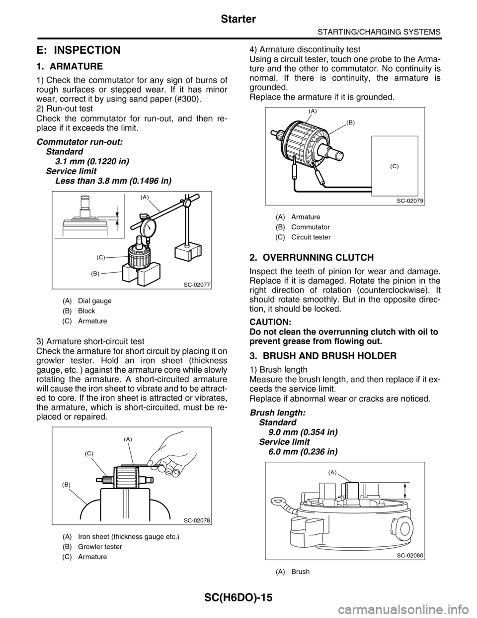
2) Run-out test
Check the commutator for run-out, and then re-
place if it exceeds the limit.
Commutator run-out:
Standard
3.1 mm (0.1220 in)
Service limit
Less than 3.8 mm (0.1496 in)
3) Armature short-circuit test
Check the armature for short circuit by placing it on
growler tester. Hold an iron sheet (thickness
gauge, etc. ) against the armature core while slowly
rotating the armature. A short-circuited armature
will cause the iron sheet to vibrate and to be attract-
ed to core. If the iron sheet is attracted or vibrates,
the armature, which is short-circuited, must be re-
placed or repaired.
4) Armature discontinuity test
Using a circuit tester, touch one probe to the Arma-
ture and the other to commutator. No continuity is
normal. If there is continuity, the armature is
grounded.
Replace the armature if it is grounded.
2. OVERRUNNING CLUTCH
Inspect the teeth of pinion for wear and damage.
Replace if it is damaged. Rotate the pinion in the
right direction of rotation (counterclockwise). It
should rotate smoothly. But in the opposite direc-
tion, it should be locked.
CAUTION:
Do not clean the overrunning clutch with oil to
prevent grease from flowing out.
3. BRUSH AND BRUSH HOLDER
1) Brush length
Measure the brush length, and then replace if it ex-
ceeds the service limit.
Replace if abnormal wear or cracks are noticed.
Brush length:
Standard
9.0 mm (0.354 in)
Service limit
6.0 mm (0.236 in)
(A) Dial gauge
(B) Block
(C) Armature
(A) Iron sheet (thickness gauge etc.)
(B) Growler tester
(C) Armature
SC-02077
(A)
(B)
(C)
SC-02078
(A)
(C)
(B)
(A) Armature
(B) Commutator
(C) Circuit tester
(A) Brush
SC-02079
(A)
(B)
(C)
SC-02080
(A)
Page 1975 of 2453
SC(H6DO)-17
Starter
STARTING/CHARGING SYSTEMS
6. SHOCK ABSORBER BEARING CLEAR-
ANCE
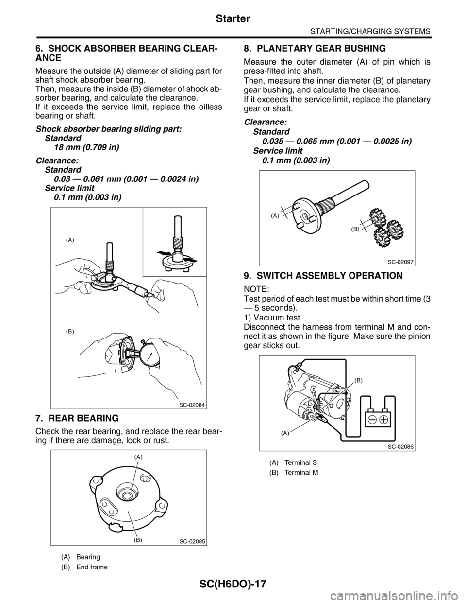
Measure the outside (A) diameter of sliding part for
shaft shock absorber bearing.
Then, measure the inside (B) diameter of shock ab-
sorber bearing, and calculate the clearance.
If it exceeds the service limit, replace the oilless
bearing or shaft.
Shock absorber bearing sliding part:
Standard
18 mm (0.709 in)
Clearance:
Standard
0.03 — 0.061 mm (0.001 — 0.0024 in)
Service limit
0.1 mm (0.003 in)
7. REAR BEARING
Check the rear bearing, and replace the rear bear-
ing if there are damage, lock or rust.
8. PLANETARY GEAR BUSHING
Measure the outer diameter (A) of pin which is
press-fitted into shaft.
Then, measure the inner diameter (B) of planetary
gear bushing, and calculate the clearance.
If it exceeds the service limit, replace the planetary
gear or shaft.
Clearance:
Standard
0.035 — 0.065 mm (0.001 — 0.0025 in)
Service limit
0.1 mm (0.003 in)
9. SWITCH ASSEMBLY OPERATION
NOTE:
Test period of each test must be within short time (3
— 5 seconds).
1) Vacuum test
Disconnect the harness from terminal M and con-
nect it as shown in the figure. Make sure the pinion
gear sticks out.
(A) Bearing
(B) End frame
SC-02084
(A)
(B)
SC-02085
(A)
(B)
(A) Terminal S
(B) Terminal M
SC-02097
(A)
(B)
SC-02086
(A)
(B)
Page 1980 of 2453
SC(H6DO)-22
Generator
STARTING/CHARGING SYSTEMS
D: ASSEMBLY
Assemble in the reverse order of disassembly.
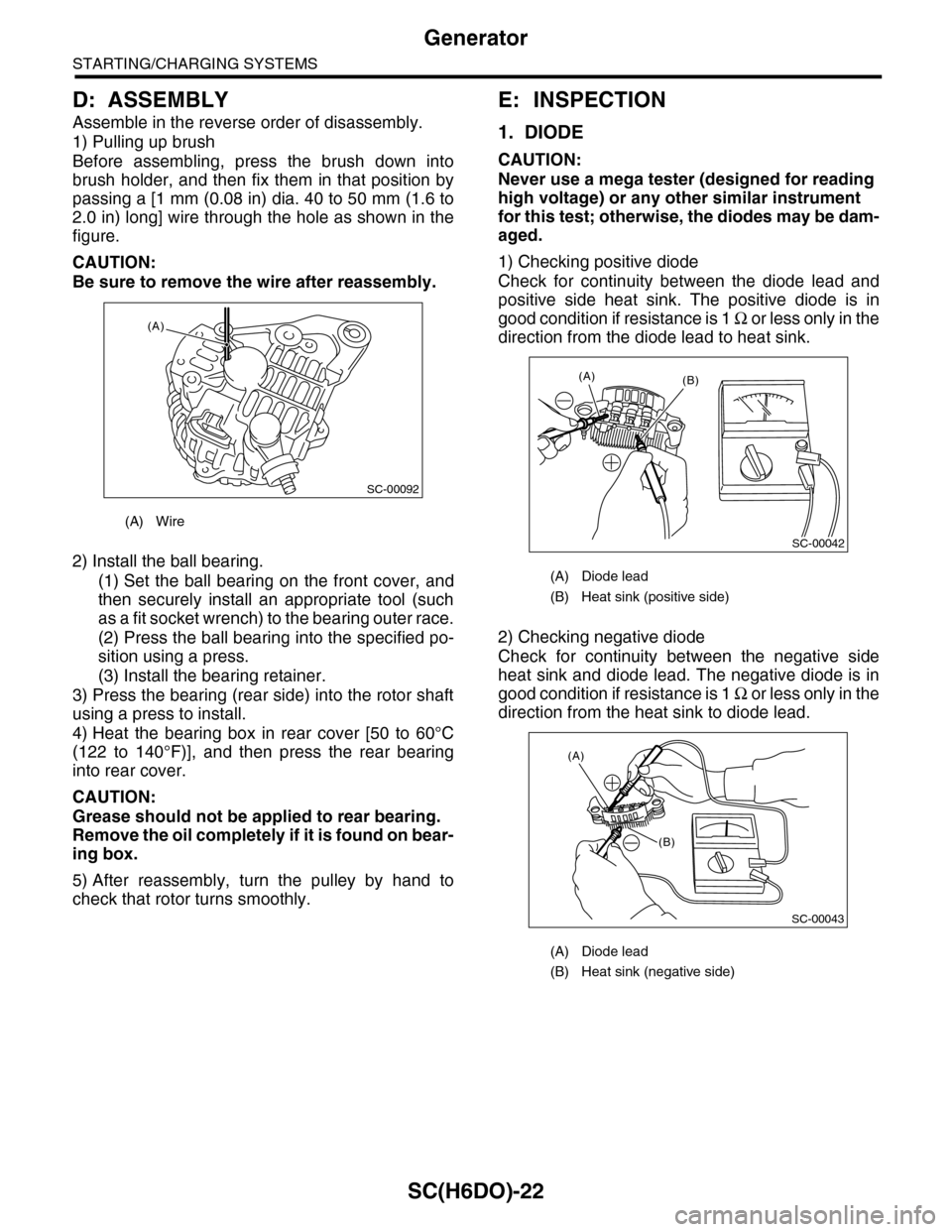
1) Pulling up brush
Before assembling, press the brush down into
brush holder, and then fix them in that position by
passing a [1 mm (0.08 in) dia. 40 to 50 mm (1.6 to
2.0 in) long] wire through the hole as shown in the
figure.
CAUTION:
Be sure to remove the wire after reassembly.
2) Install the ball bearing.
(1) Set the ball bearing on the front cover, and
then securely install an appropriate tool (such
as a fit socket wrench) to the bearing outer race.
(2) Press the ball bearing into the specified po-
sition using a press.
(3) Install the bearing retainer.
3) Press the bearing (rear side) into the rotor shaft
using a press to install.
4) Heat the bearing box in rear cover [50 to 60°C
(122 to 140°F)], and then press the rear bearing
into rear cover.
CAUTION:
Grease should not be applied to rear bearing.
Remove the oil completely if it is found on bear-
ing box.
5) After reassembly, turn the pulley by hand to
check that rotor turns smoothly.
E: INSPECTION
1. DIODE
CAUTION:
Never use a mega tester (designed for reading
high voltage) or any other similar instrument
for this test; otherwise, the diodes may be dam-
aged.
1) Checking positive diode
Check for continuity between the diode lead and
positive side heat sink. The positive diode is in
good condition if resistance is 1 Ω o r l e s s o n l y i n t h e
direction from the diode lead to heat sink.
2) Checking negative diode
Check for continuity between the negative side
heat sink and diode lead. The negative diode is in
good condition if resistance is 1 Ω o r l e s s o n l y i n t h e
direction from the heat sink to diode lead.
(A) Wire
SC-00092
(A)
(A) Diode lead
(B) Heat sink (positive side)
(A) Diode lead
(B) Heat sink (negative side)
SC-00042
(B)(A)
(A)
(B)
SC-00043
Page 1981 of 2453
SC(H6DO)-23
Generator
STARTING/CHARGING SYSTEMS
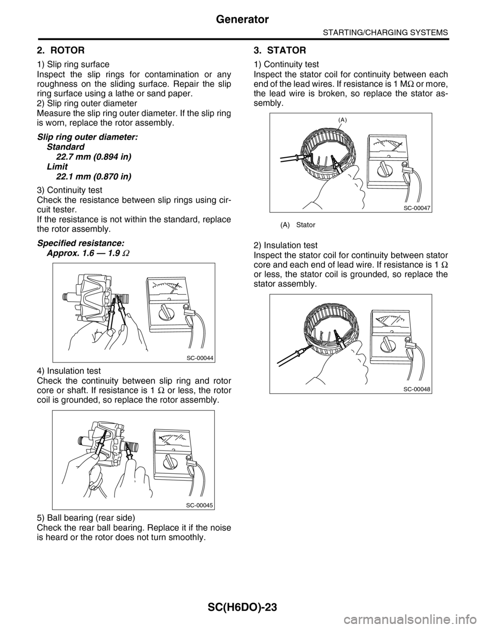
2. ROTOR
1) Slip ring surface
Inspect the slip rings for contamination or any
roughness on the sliding surface. Repair the slip
ring surface using a lathe or sand paper.
2) Slip ring outer diameter
Measure the slip ring outer diameter. If the slip ring
is worn, replace the rotor assembly.
Slip ring outer diameter:
Standard
22.7 mm (0.894 in)
Limit
22.1 mm (0.870 in)
3) Continuity test
Check the resistance between slip rings using cir-
cuit tester.
If the resistance is not within the standard, replace
the rotor assembly.
Specified resistance:
Approx. 1.6 — 1.9 Ω
4) Insulation test
Check the continuity between slip ring and rotor
core or shaft. If resistance is 1 Ω or less, the rotor
coil is grounded, so replace the rotor assembly.
5) Ball bearing (rear side)
Check the rear ball bearing. Replace it if the noise
is heard or the rotor does not turn smoothly.
3. STATOR
1) Continuity test
Inspect the stator coil for continuity between each
end of the lead wires. If resistance is 1 MΩ o r m o r e ,
the lead wire is broken, so replace the stator as-
sembly.
2) Insulation test
Inspect the stator coil for continuity between stator
core and each end of lead wire. If resistance is 1 Ω
or less, the stator coil is grounded, so replace the
stator assembly.
SC-00044
SC-00045
(A) Stator
(A)
SC-00047
SC-00048
Page 1989 of 2453
PM-6
Engine Oil
PERIODIC MAINTENANCE SERVICES
3. Engine Oil
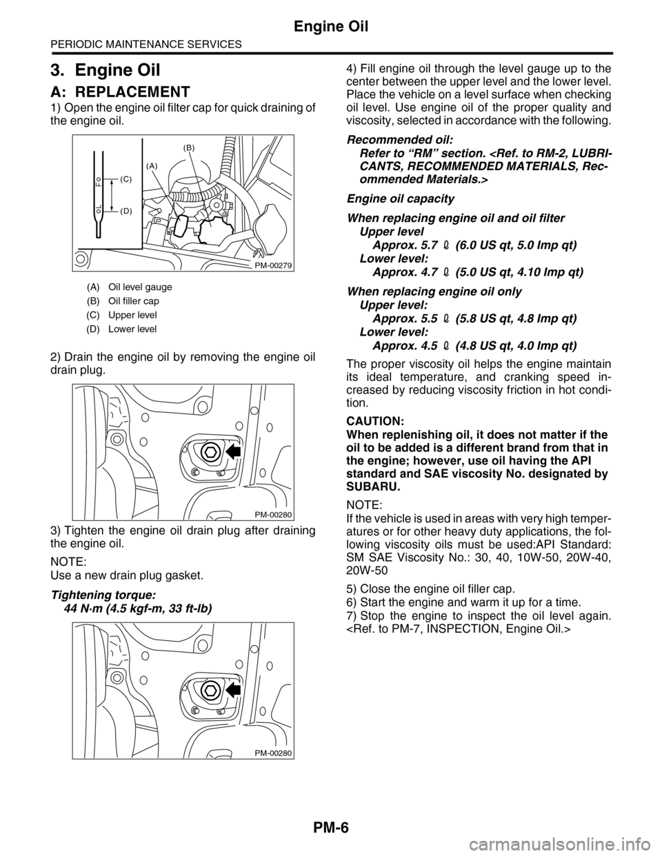
A: REPLACEMENT
1) Open the engine oil filter cap for quick draining of
the engine oil.
2) Drain the engine oil by removing the engine oil
drain plug.
3) Tighten the engine oil drain plug after draining
the engine oil.
NOTE:
Use a new drain plug gasket.
Tightening torque:
44 N·m (4.5 kgf-m, 33 ft-lb)
4) Fill engine oil through the level gauge up to the
center between the upper level and the lower level.
Place the vehicle on a level surface when checking
oil level. Use engine oil of the proper quality and
viscosity, selected in accordance with the following.
Recommended oil:
Refer to “RM” section.
ommended Materials.>
Engine oil capacity
When replacing engine oil and oil filter
Upper level
Approx. 5.7 2 (6.0 US qt, 5.0 Imp qt)
Lower level:
Approx. 4.7 2 (5.0 US qt, 4.10 Imp qt)
When replacing engine oil only
Upper level:
Approx. 5.5 2 (5.8 US qt, 4.8 Imp qt)
Lower level:
Approx. 4.5 2 (4.8 US qt, 4.0 Imp qt)
The proper viscosity oil helps the engine maintain
its ideal temperature, and cranking speed in-
creased by reducing viscosity friction in hot condi-
tion.
CAUTION:
When replenishing oil, it does not matter if the
oil to be added is a different brand from that in
the engine; however, use oil having the API
standard and SAE viscosity No. designated by
SUBARU.
NOTE:
If the vehicle is used in areas with very high temper-
atures or for other heavy duty applications, the fol-
lowing viscosity oils must be used:API Standard:
SM SAE Viscosity No.: 30, 40, 10W-50, 20W-40,
20W-50
5) Close the engine oil filler cap.
6) Start the engine and warm it up for a time.
7) Stop the engine to inspect the oil level again.
(A) Oil level gauge
(B) Oil filler cap
(C) Upper level
(D) Lower level
PM-00279
(A)
(B)
(C)
(D)
PM-00280
PM-00280
Page 1990 of 2453
PM-7
Engine Oil
PERIODIC MAINTENANCE SERVICES
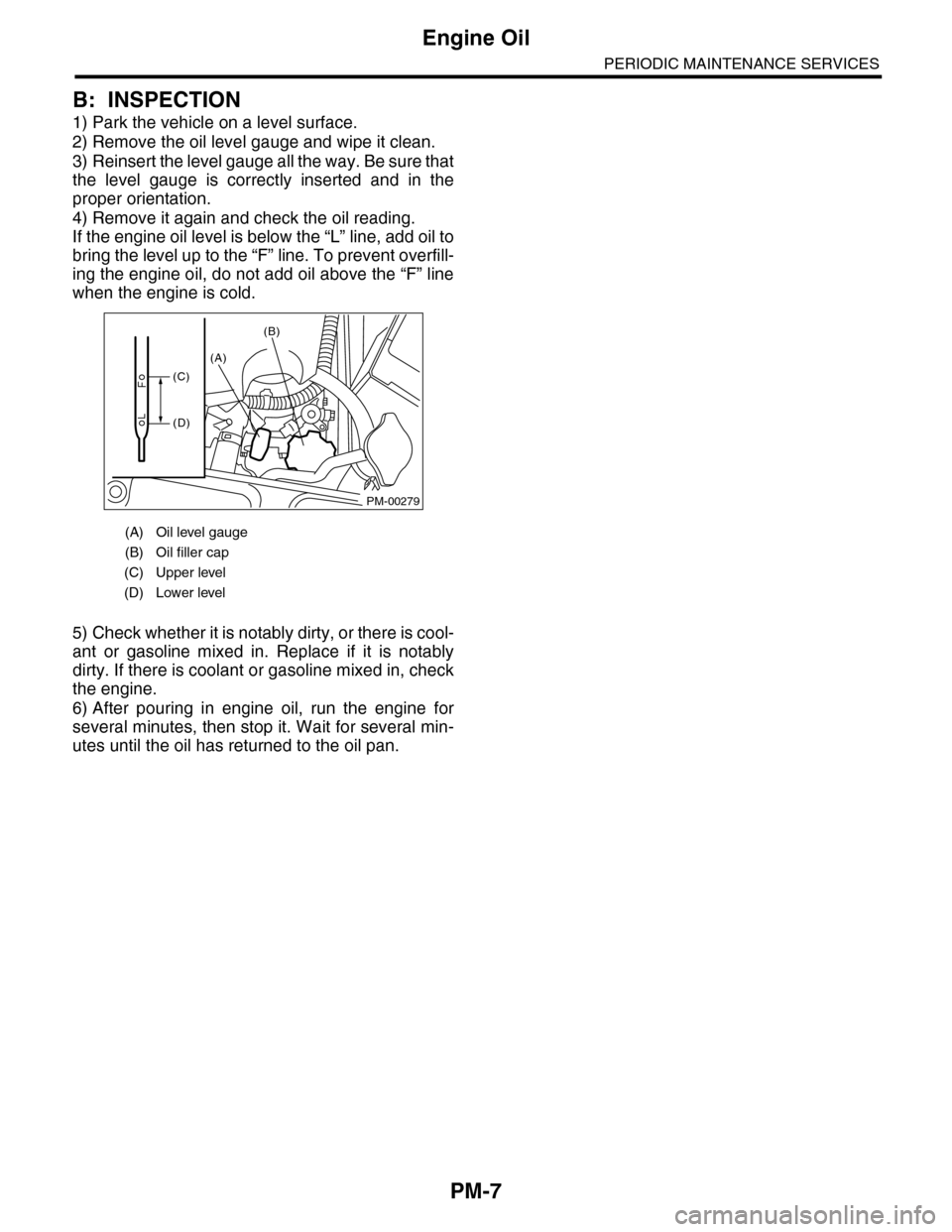
B: INSPECTION
1) Park the vehicle on a level surface.
2) Remove the oil level gauge and wipe it clean.
3) Reinsert the level gauge all the way. Be sure that
the level gauge is correctly inserted and in the
proper orientation.
4) Remove it again and check the oil reading.
If the engine oil level is below the “L” line, add oil to
bring the level up to the “F” line. To prevent overfill-
ing the engine oil, do not add oil above the “F” line
when the engine is cold.
5) Check whether it is notably dirty, or there is cool-
ant or gasoline mixed in. Replace if it is notably
dirty. If there is coolant or gasoline mixed in, check
the engine.
6) After pouring in engine oil, run the engine for
several minutes, then stop it. Wait for several min-
utes until the oil has returned to the oil pan.
(A) Oil level gauge
(B) Oil filler cap
(C) Upper level
(D) Lower level
PM-00279
(A)
(B)
(C)
(D)
Page 1991 of 2453
PM-8
Engine Oil Filter
PERIODIC MAINTENANCE SERVICES
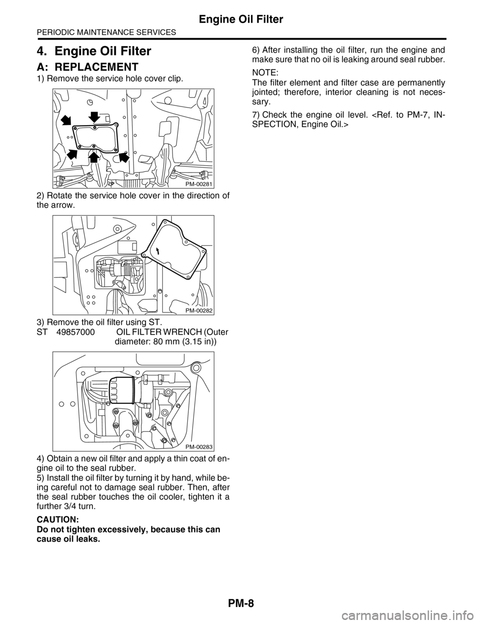
4. Engine Oil Filter
A: REPLACEMENT
1) Remove the service hole cover clip.
2) Rotate the service hole cover in the direction of
the arrow.
3) Remove the oil filter using ST.
ST 49857000 OIL FILTER WRENCH (Outer
diameter: 80 mm (3.15 in))
4) Obtain a new oil filter and apply a thin coat of en-
gine oil to the seal rubber.
5) Install the oil filter by turning it by hand, while be-
ing careful not to damage seal rubber. Then, after
the seal rubber touches the oil cooler, tighten it a
further 3/4 turn.
CAUTION:
Do not tighten excessively, because this can
cause oil leaks.
6) After installing the oil filter, run the engine and
make sure that no oil is leaking around seal rubber.
NOTE:
The filter element and filter case are permanently
jointed; therefore, interior cleaning is not neces-
sary.
7) Check the engine oil level.
PM-00281
PM-00282
PM-00283