2009 SUBARU TRIBECA check oil
[x] Cancel search: check oilPage 1924 of 2453
ME(H6DO)-58
Cylinder Head
MECHANICAL
8) Install the front chain cover.
9) Install the crank pulley.
C: DISASSEMBLY
1) Set the cylinder head on ST.
ST 18250AA010 CYLINDER HEAD TABLE
2) Remove the valve lifter.
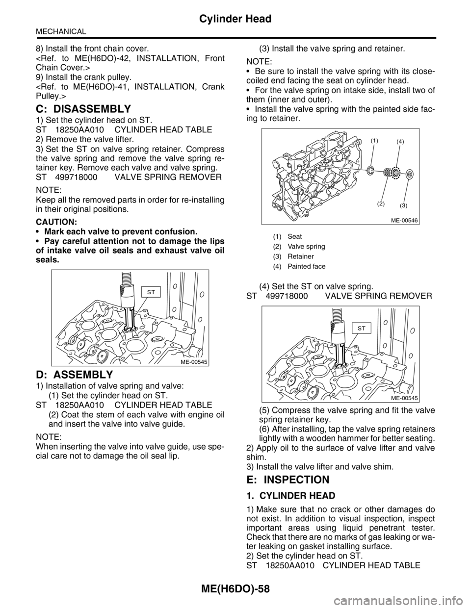
3) Set the ST on valve spring retainer. Compress
the valve spring and remove the valve spring re-
tainer key. Remove each valve and valve spring.
ST 499718000 VALVE SPRING REMOVER
NOTE:
Keep all the removed parts in order for re-installing
in their original positions.
CAUTION:
•Mark each valve to prevent confusion.
•Pay careful attention not to damage the lips
of intake valve oil seals and exhaust valve oil
seals.
D: ASSEMBLY
1) Installation of valve spring and valve:
(1) Set the cylinder head on ST.
ST 18250AA010 CYLINDER HEAD TABLE
(2) Coat the stem of each valve with engine oil
and insert the valve into valve guide.
NOTE:
When inserting the valve into valve guide, use spe-
cial care not to damage the oil seal lip.
(3) Install the valve spring and retainer.
NOTE:
•Be sure to install the valve spring with its close-
coiled end facing the seat on cylinder head.
•For the valve spring on intake side, install two of
them (inner and outer).
•Install the valve spring with the painted side fac-
ing to retainer.
(4) Set the ST on valve spring.
ST 499718000 VALVE SPRING REMOVER
(5) Compress the valve spring and fit the valve
spring retainer key.
(6) After installing, tap the valve spring retainers
lightly with a wooden hammer for better seating.
2) Apply oil to the surface of valve lifter and valve
shim.
3) Install the valve lifter and valve shim.
E: INSPECTION
1. CYLINDER HEAD
1) Make sure that no crack or other damages do
not exist. In addition to visual inspection, inspect
important areas using liquid penetrant tester.
Check that there are no marks of gas leaking or wa-
ter leaking on gasket installing surface.
2) Set the cylinder head on ST.
ST 18250AA010 CYLINDER HEAD TABLE
ST
ME-00545
(1) Seat
(2) Valve spring
(3) Retainer
(4) Painted face
(1)
(2)(3)
(4)
ME-00546
ST
ME-00545
Page 1926 of 2453
ME(H6DO)-60
Cylinder Head
MECHANICAL
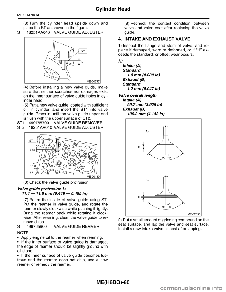
(3) Turn the cylinder head upside down and
place the ST as shown in the figure.
ST 18251AA040 VALVE GUIDE ADJUSTER
(4) Before installing a new valve guide, make
sure that neither scratches nor damages exist
on the inner surface of valve guide holes in cyl-
inder head.
(5) Put a new valve guide, coated with sufficient
oil, in cylinder, and insert the ST1 into valve
guide. Press in until the valve guide upper end
is flush with the upper surface of ST2.
ST1 499765700 VALVE GUIDE REMOVER
ST2 18251AA040 VALVE GUIDE ADJUSTER
(6) Check the valve guide protrusion.
Valve guide protrusion L:
11.4 — 11.8 mm (0.449 — 0.465 in)
(7) Ream the inside of valve guide using ST.
Put the reamer in valve guide, and rotate the
reamer slowly clockwise while pushing it lightly.
Bring the reamer back while rotating it clock-
wise. After reaming, clean the valve guide to re-
move chips.
ST 499765900 VALVE GUIDE REAMER
NOTE:
•Apply engine oil to the reamer when reaming.
•If the inner surface of valve guide is damaged,
the edge of reamer should be slightly ground with
oil stone.
•If the inner surface of valve guide becomes lus-
trous and the reamer does not chip, use a new
reamer or remedy the reamer.
(8) Recheck the contact condition between
valve and valve seat after replacing the valve
guide.
4. INTAKE AND EXHAUST VALVE
1) Inspect the flange and stem of valve, and re-
place if damaged, worn or deformed, or if “H” ex-
ceeds the standard, or offset wear occurs.
H:
Intake (A)
Standard
1.0 mm (0.039 in)
Exhaust (B)
Standard
1.2 mm (0.047 in)
Valve overall length:
Intake (A)
99.7 mm (3.925 in)
Exhaust (B)
105.2 mm (4.142 in)
2) Put a small amount of grinding compound on the
seat surface, and lap the valve and seat surface.
Install a new intake valve oil seal after lapping.
ME-00757
ST
L
ME-00130
ST1
ST2
ME-02096
H
H
(B)
(A)
90 0+1
90 0+1
Page 1927 of 2453
ME(H6DO)-61
Cylinder Head
MECHANICAL
5. VALVE SPRING
1) Check the valve springs for damage, free length,
and tension. Replace the valve spring if it is not
within the standard value presented in the table.
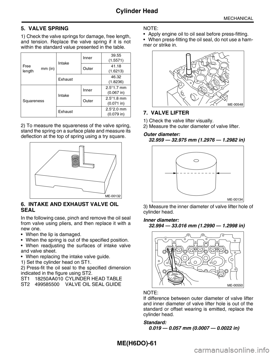
2) To measure the squareness of the valve spring,
stand the spring on a surface plate and measure its
deflection at the top of spring using a try square.
6. INTAKE AND EXHAUST VALVE OIL
SEAL
In the following case, pinch and remove the oil seal
from valve using pliers, and then replace it with a
new one.
•When the lip is damaged.
•When the spring is out of the specified position.
•When readjusting the surfaces of intake valve
and valve sheet.
•When replacing the intake valve guide.
1) Set the cylinder head on ST1.
2) Press-fit the oil seal to the specified dimension
indicated in the figure using ST2.
ST1 18250AA010 CYLINDER HEAD TABLE
ST2 499585500 VALVE OIL SEAL GUIDE
NOTE:
•Apply engine oil to oil seal before press-fitting.
•When press-fitting the oil seal, do not use a ham-
mer or strike in.
7. VALVE LIFTER
1) Check the valve lifter visually.
2) Measure the outer diameter of valve lifter.
Outer diameter:
32.959 — 32.975 mm (1.2976 — 1.2982 in)
3) Measure the inner diameter of valve lifter hole of
cylinder head.
Inner diameter:
32.994 — 33.016 mm (1.2990 — 1.2998 in)
NOTE:
If difference between outer diameter of valve lifter
and inner diameter of valve lifter hole is out of the
standard or offset wearing is emitted, replace the
cylinder head.
Standard:
0.019 — 0.057 mm (0.0007 — 0.0022 in)
Fr e e
lengthmm (in)
Intake
Inner39.55
(1.5571)
Outer41.18
(1.6213)
Exhaust46.32
(1.8236)
Squareness
Intake
Inner2.5°1.7 mm
(0.067 in)
Outer2.5°1.8 mm
(0.071 in)
Exhaust2.5°2.0 mm
(0.079 in)
ME-00132
ME-00548
ME-00134
ME-00550
Page 1936 of 2453
ME(H6DO)-70
Cylinder Block
MECHANICAL
D: ASSEMBLY
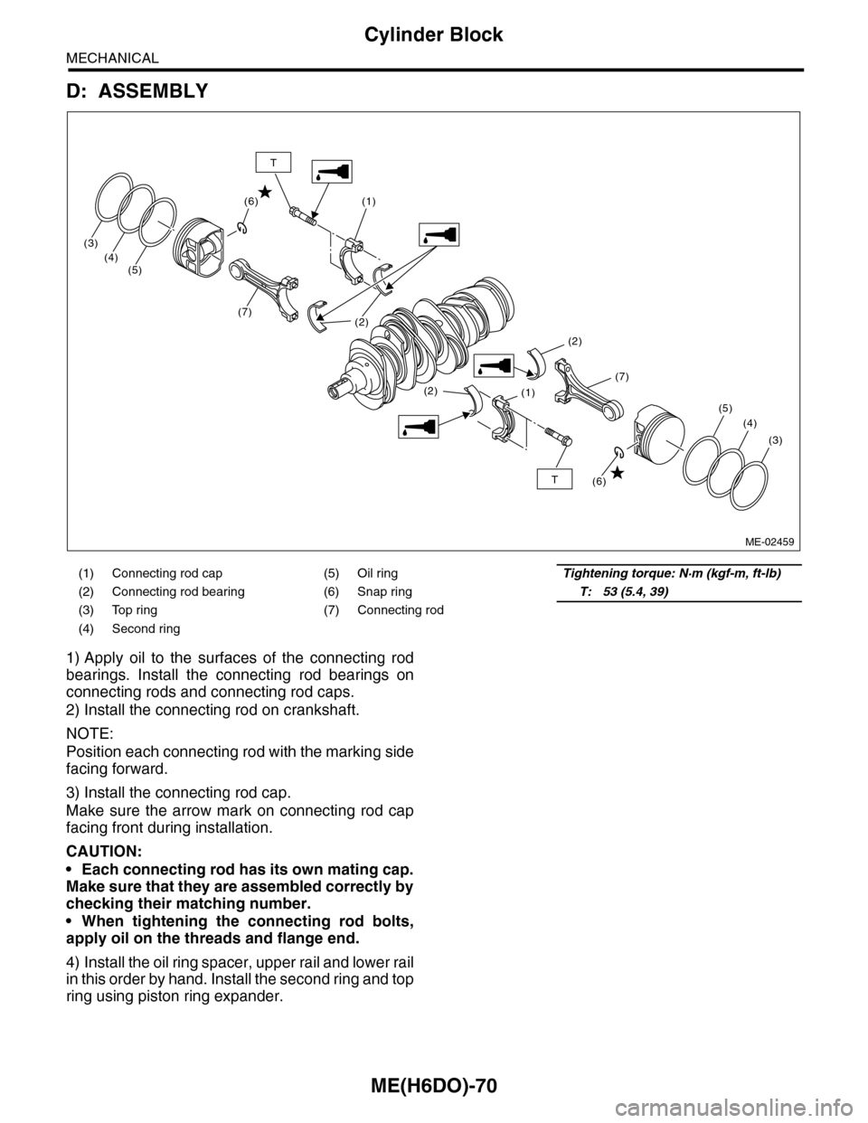
1) Apply oil to the surfaces of the connecting rod
bearings. Install the connecting rod bearings on
connecting rods and connecting rod caps.
2) Install the connecting rod on crankshaft.
NOTE:
Position each connecting rod with the marking side
facing forward.
3) Install the connecting rod cap.
Make sure the arrow mark on connecting rod cap
facing front during installation.
CAUTION:
•Each connecting rod has its own mating cap.
Make sure that they are assembled correctly by
checking their matching number.
•When tightening the connecting rod bolts,
apply oil on the threads and flange end.
4) Install the oil ring spacer, upper rail and lower rail
in this order by hand. Install the second ring and top
ring using piston ring expander.
(1) Connecting rod cap (5) Oil ringTightening torque: N·m (kgf-m, ft-lb)
(2) Connecting rod bearing (6) Snap ringT: 53 (5.4, 39)
(3) Top ring (7) Connecting rod
(4) Second ring
(1)
(1)
(2)
(2)
(2)
(7)
(3)
(4)(5)
(7)
(3)
(4)
(5)
(6)
(6)T
T
ME-02459
Page 1937 of 2453
ME(H6DO)-71
Cylinder Block
MECHANICAL
E: INSPECTION
1. CYLINDER BLOCK
1) Visually check for cracks and damage. Especial-
ly, inspect the important parts using liquid pene-
trant tester.
2) Check the oil passages for clogging.
3) Inspect the crankcase surface that mates with
cylinder head for warping by using a straight edge.
Standard height of cylinder block:
202 mm (7.95 in)
2. CYLINDER AND PISTON
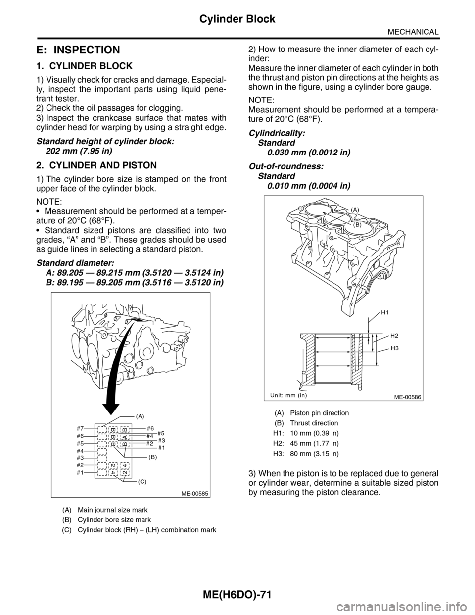
1) The cylinder bore size is stamped on the front
upper face of the cylinder block.
NOTE:
•Measurement should be performed at a temper-
ature of 20°C (68°F).
•Standard sized pistons are classified into two
grades, “A” and “B”. These grades should be used
as guide lines in selecting a standard piston.
Standard diameter:
A: 89.205 — 89.215 mm (3.5120 — 3.5124 in)
B: 89.195 — 89.205 mm (3.5116 — 3.5120 in)
2) How to measure the inner diameter of each cyl-
inder:
Measure the inner diameter of each cylinder in both
the thrust and piston pin directions at the heights as
shown in the figure, using a cylinder bore gauge.
NOTE:
Measurement should be performed at a tempera-
ture of 20°C (68°F).
Cylindricality:
Standard
0.030 mm (0.0012 in)
Out-of-roundness:
Standard
0.010 mm (0.0004 in)
3) When the piston is to be replaced due to general
or cylinder wear, determine a suitable sized piston
by measuring the piston clearance.
(A) Main journal size mark
(B) Cylinder bore size mark
(C) Cylinder block (RH) – (LH) combination mark
#7 #6#5
#2#1
#4#3#6#5#4#3#2#1
BBB 2
42BAB4
(A)
(B)
(C)
ME-00585
(A) Piston pin direction
(B) Thrust direction
H1: 10 mm (0.39 in)
H2: 45 mm (1.77 in)
H3: 80 mm (3.15 in)
ME-00586
H1
H2
H3
Unit: mm (in)
(B)
(A)
Page 1939 of 2453
ME(H6DO)-73
Cylinder Block
MECHANICAL
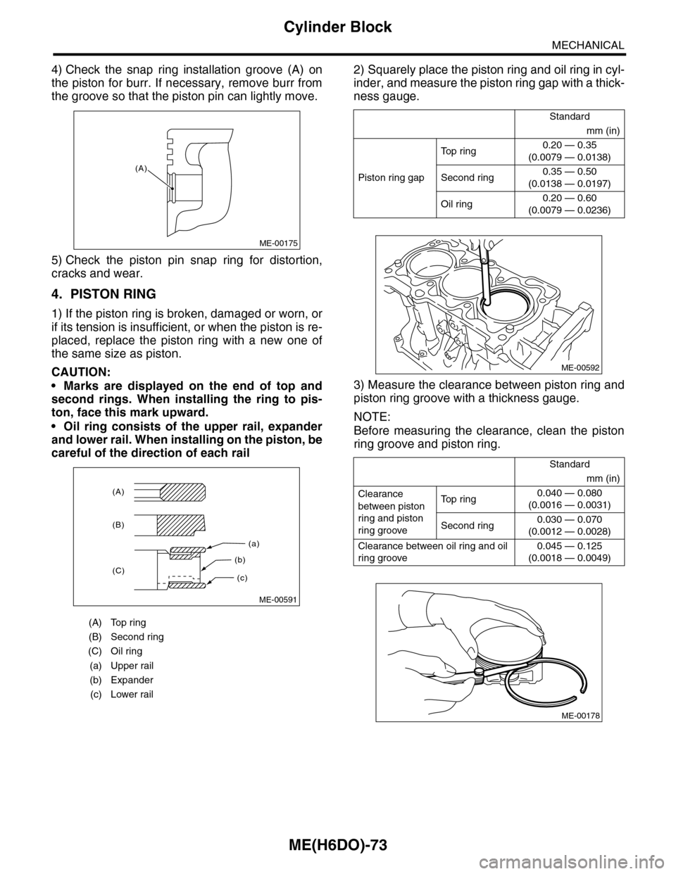
4) Check the snap ring installation groove (A) on
the piston for burr. If necessary, remove burr from
the groove so that the piston pin can lightly move.
5) Check the piston pin snap ring for distortion,
cracks and wear.
4. PISTON RING
1) If the piston ring is broken, damaged or worn, or
if its tension is insufficient, or when the piston is re-
placed, replace the piston ring with a new one of
the same size as piston.
CAUTION:
•Marks are displayed on the end of top and
second rings. When installing the ring to pis-
ton, face this mark upward.
•Oil ring consists of the upper rail, expander
and lower rail. When installing on the piston, be
careful of the direction of each rail
2) Squarely place the piston ring and oil ring in cyl-
inder, and measure the piston ring gap with a thick-
ness gauge.
3) Measure the clearance between piston ring and
piston ring groove with a thickness gauge.
NOTE:
Before measuring the clearance, clean the piston
ring groove and piston ring.
(A) Top ring
(B) Second ring
(C) Oil ring
(a) Upper rail
(b) Expander
(c) Lower rail
ME-00175
(A)
(a)
(c)
(b)
(A)
(B)
(C)
ME-00591
Standard
mm (in)
Piston ring gap
To p r i n g0.20 — 0.35
(0.0079 — 0.0138)
Second ring0.35 — 0.50
(0.0138 — 0.0197)
Oil ring0.20 — 0.60
(0.0079 — 0.0236)
Standard
mm (in)
Clearance
between piston
ring and piston
ring groove
To p r i n g0.040 — 0.080
(0.0016 — 0.0031)
Second ring0.030 — 0.070
(0.0012 — 0.0028)
Clearance between oil ring and oil
ring groove
0.045 — 0.125
(0.0018 — 0.0049)
ME-00592
ME-00178
Page 1940 of 2453
ME(H6DO)-74
Cylinder Block
MECHANICAL
5. CONNECTING ROD
1) Replace the connecting rod, if the large or small
end thrust surface is damaged.
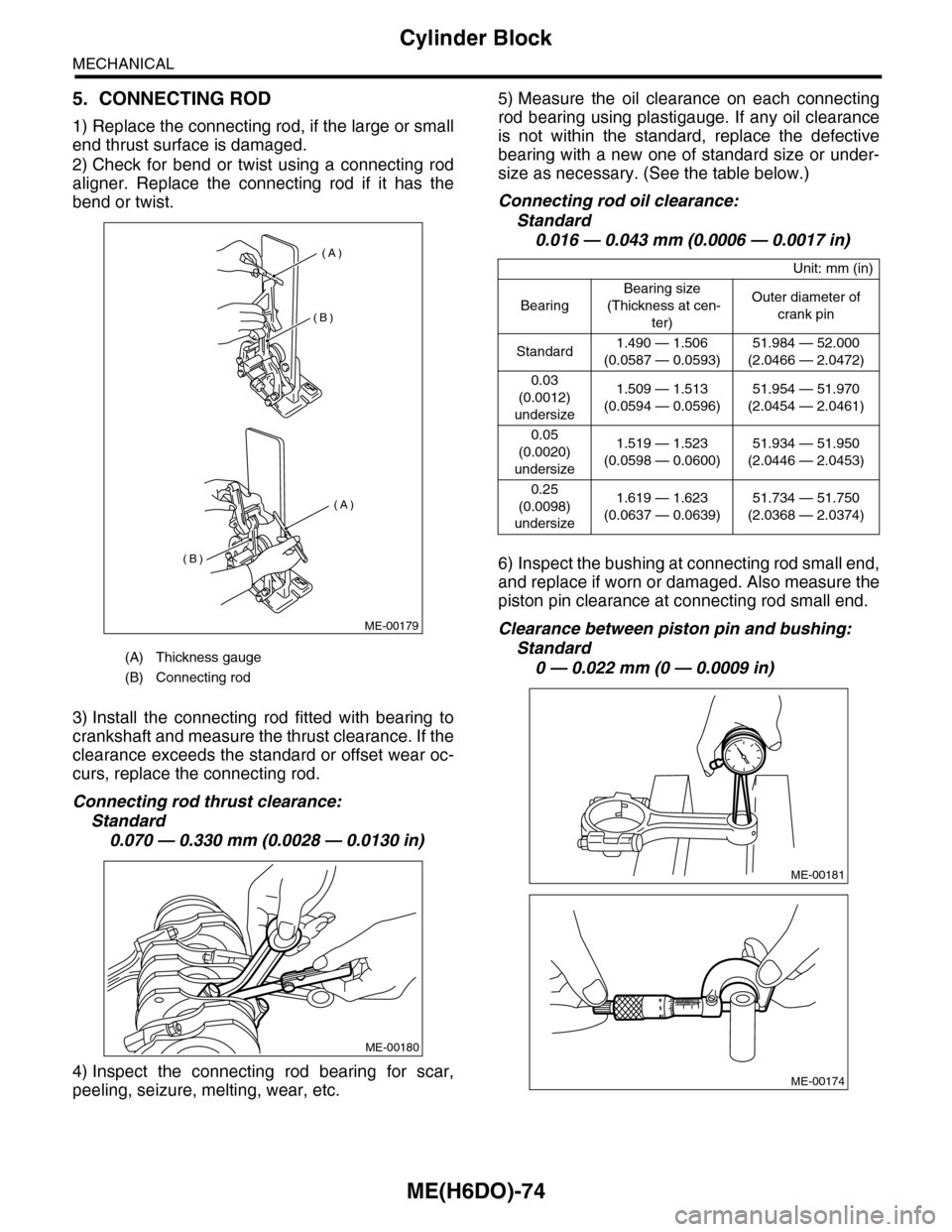
2) Check for bend or twist using a connecting rod
aligner. Replace the connecting rod if it has the
bend or twist.
3) Install the connecting rod fitted with bearing to
crankshaft and measure the thrust clearance. If the
clearance exceeds the standard or offset wear oc-
curs, replace the connecting rod.
Connecting rod thrust clearance:
Standard
0.070 — 0.330 mm (0.0028 — 0.0130 in)
4) Inspect the connecting rod bearing for scar,
peeling, seizure, melting, wear, etc.
5) Measure the oil clearance on each connecting
rod bearing using plastigauge. If any oil clearance
is not within the standard, replace the defective
bearing with a new one of standard size or under-
size as necessary. (See the table below.)
Connecting rod oil clearance:
Standard
0.016 — 0.043 mm (0.0006 — 0.0017 in)
6) Inspect the bushing at connecting rod small end,
and replace if worn or damaged. Also measure the
piston pin clearance at connecting rod small end.
Clearance between piston pin and bushing:
Standard
0 — 0.022 mm (0 — 0.0009 in)(A) Thickness gauge
(B) Connecting rod
(A)
(A)
(B)
(B)
ME-00179
ME-00180
Unit: mm (in)
Bearing
Bearing size
(Thickness at cen-
ter)
Outer diameter of
crank pin
Standard1.490 — 1.506
(0.0587 — 0.0593)
51.984 — 52.000
(2.0466 — 2.0472)
0.03
(0.0012)
undersize
1.509 — 1.513
(0.0594 — 0.0596)
51.954 — 51.970
(2.0454 — 2.0461)
0.05
(0.0020)
undersize
1.519 — 1.523
(0.0598 — 0.0600)
51.934 — 51.950
(2.0446 — 2.0453)
0.25
(0.0098)
undersize
1.619 — 1.623
(0.0637 — 0.0639)
51.734 — 51.750
(2.0368 — 2.0374)
ME-00181
ME-00174
Page 1941 of 2453
ME(H6DO)-75
Cylinder Block
MECHANICAL
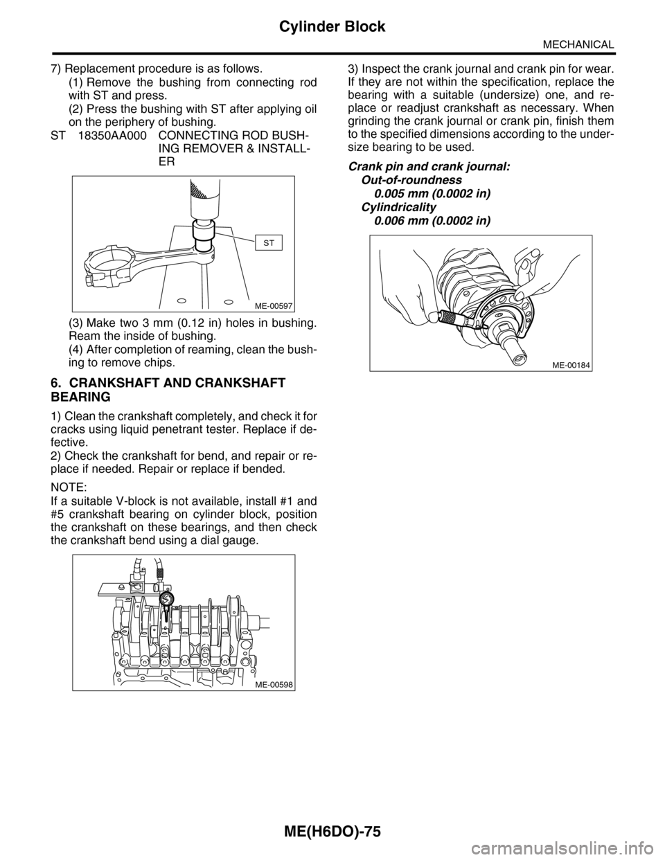
7) Replacement procedure is as follows.
(1) Remove the bushing from connecting rod
with ST and press.
(2) Press the bushing with ST after applying oil
on the periphery of bushing.
ST 18350AA000 CONNECTING ROD BUSH-
ING REMOVER & INSTALL-
ER
(3) Make two 3 mm (0.12 in) holes in bushing.
Ream the inside of bushing.
(4) After completion of reaming, clean the bush-
ing to remove chips.
6. CRANKSHAFT AND CRANKSHAFT
BEARING
1) Clean the crankshaft completely, and check it for
cracks using liquid penetrant tester. Replace if de-
fective.
2) Check the crankshaft for bend, and repair or re-
place if needed. Repair or replace if bended.
NOTE:
If a suitable V-block is not available, install #1 and
#5 crankshaft bearing on cylinder block, position
the crankshaft on these bearings, and then check
the crankshaft bend using a dial gauge.
3) Inspect the crank journal and crank pin for wear.
If they are not within the specification, replace the
bearing with a suitable (undersize) one, and re-
place or readjust crankshaft as necessary. When
grinding the crank journal or crank pin, finish them
to the specified dimensions according to the under-
size bearing to be used.
Crank pin and crank journal:
Out-of-roundness
0.005 mm (0.0002 in)
Cylindricality
0.006 mm (0.0002 in)
ST
ME-00597
ME-00598
ME-00184