Page 1866 of 2453
LU(H6DO)-17
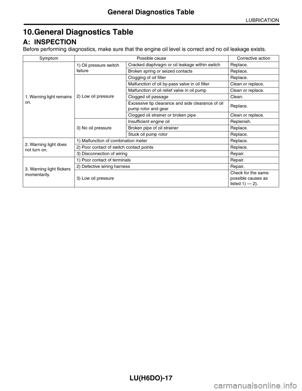
General Diagnostics Table
LUBRICATION
10.General Diagnostics Table
A: INSPECTION
Before performing diagnostics, make sure that the engine oil level is correct and no oil leakage exists.
Symptom Possible cause Corrective action
1. Warning light remains
on.
1) Oil pressure switch
failure
Cracked diaphragm or oil leakage within switch Replace.
Broken spring or seized contacts Replace.
2) Low oil pressure
Clogging of oil filter Replace.
Malfunction of oil by-pass valve in oil filter Clean or replace.
Malfunction of oil relief valve in oil pump Clean or replace.
Clogged oil passage Clean.
Excessive tip clearance and side clearance of oil
pump rotor and gearReplace.
Clogged oil strainer or broken pipe Clean or replace.
3) No oil pressure
Insufficient engine oil Replenish.
Broken pipe of oil strainer Replace.
Stuck oil pump rotor Replace.
2. Warning light does
not turn on.
1) Malfunction of combination meter Replace.
2) Poor contact of switch contact points Replace.
3) Disconnection of wiring Repair.
3. Warning light flickers
momentarily.
1) Poor contact of terminals Repair.
2) Defective wiring harness Repair.
3) Low oil pressure
Check for the same
possible causes as
listed 1) — 2).
Page 1880 of 2453
ME(H6DO)-14
General Description
MECHANICAL
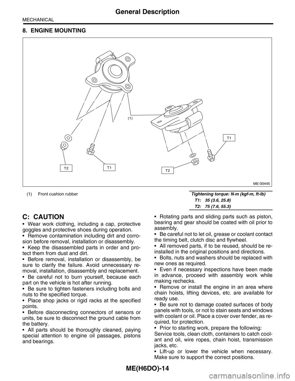
8. ENGINE MOUNTING
C: CAUTION
•Wear work clothing, including a cap, protective
goggles and protective shoes during operation.
•Remove contamination including dirt and corro-
sion before removal, installation or disassembly.
•Keep the disassembled parts in order and pro-
tect them from dust and dirt.
•Before removal, installation or disassembly, be
sure to clarify the failure. Avoid unnecessary re-
moval, installation, disassembly and replacement.
•Be careful not to burn yourself, because each
part on the vehicle is hot after running.
•Be sure to tighten fasteners including bolts and
nuts to the specified torque.
•Place shop jacks or rigid racks at the specified
points.
•Before disconnecting connectors of sensors or
units, be sure to disconnect the ground cable from
the battery.
•All parts should be thoroughly cleaned, paying
special attention to engine oil passages, pistons
and bearings.
•Rotating parts and sliding parts such as piston,
bearing and gear should be coated with oil prior to
assembly.
•Be careful not to let oil, grease or coolant contact
the timing belt, clutch disc and flywheel.
•All removed parts, if to be reused, should be re-
installed in the original positions and directions.
•Bolts, nuts and washers should be replaced with
new ones as required.
•Even if necessary inspections have been made
in advance, proceed with assembly work while
making rechecks.
•Remove or install the engine in an area where
chain hoists, lifting devices, etc. are available for
ready use.
•Be sure not to damage coated surfaces of body
panels with tools, or not to stain seats and windows
with coolant or oil. Place a cover over fender, as re-
quired, for protection.
•Prior to starting work, prepare the following:
Service tools, clean cloth, containers to catch cool-
ant and oil, wire ropes, chain hoist, transmission
jacks, etc.
•Lift-up or lower the vehicle when necessary.
Make sure to support the correct positions.
(1) Front cushion rubber Tightening torque: N·m (kgf-m, ft-lb)
T1: 35 (3.6, 25.8)
T2: 75 (7.6, 55.3)
(1)
T2
T1
T1T2
ME-00445
Page 1891 of 2453
ME(H6DO)-25
Engine Oil Pressure
MECHANICAL
6. Engine Oil Pressure
A: INSPECTION
1) Remove the oil pressure switch from cylinder
block.
Pressure Switch.>
2) Connect the oil pressure gauge hose to cylinder
block.
3) Connect the ground cable to the battery.
4) Start the engine, and measure the oil pressure.
OIL PRESSURE (at oil temperature of 80°C
(176°F)):
Standard:
135 kPa (1.4 kgf/cm2, 20 psi) or more (at
600 rpm)
500 kPa (5.1 kgf/cm2, 73 psi) or more (at
5,000 rpm)
CAUTION:
•If the oil pressure is out of specification,
check oil pump, oil filter and lubrication line.
Diagnostics Table.>
•If the oil pressure warning light is turned ON
and oil pressure is in specification, replace the
oil pressure switch.
SPECTION, General Diagnostics Table.>
5) After measuring the oil pressure, install the oil
pressure switch.
LATION, Oil Pressure Switch.>
Tightening torque:
25 N·m (2.5 kgf-m, 18 ft-lb)
Page 1901 of 2453
ME(H6DO)-35
Engine Assembly
MECHANICAL
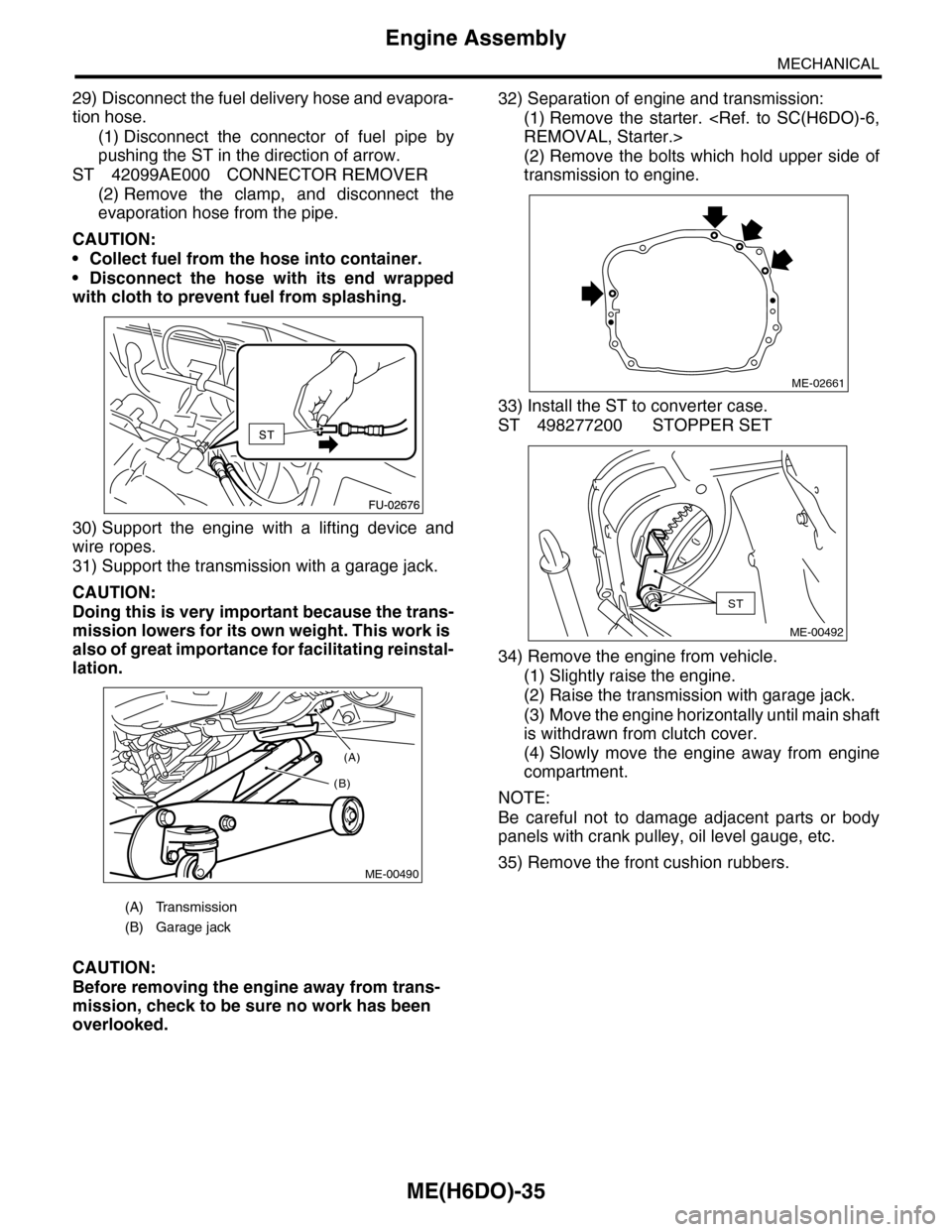
29) Disconnect the fuel delivery hose and evapora-
tion hose.
(1) Disconnect the connector of fuel pipe by
pushing the ST in the direction of arrow.
ST 42099AE000 CONNECTOR REMOVER
(2) Remove the clamp, and disconnect the
evaporation hose from the pipe.
CAUTION:
•Collect fuel from the hose into container.
•Disconnect the hose with its end wrapped
with cloth to prevent fuel from splashing.
30) Support the engine with a lifting device and
wire ropes.
31) Support the transmission with a garage jack.
CAUTION:
Doing this is very important because the trans-
mission lowers for its own weight. This work is
also of great importance for facilitating reinstal-
lation.
CAUTION:
Before removing the engine away from trans-
mission, check to be sure no work has been
overlooked.
32) Separation of engine and transmission:
(1) Remove the starter.
REMOVAL, Starter.>
(2) Remove the bolts which hold upper side of
transmission to engine.
33) Install the ST to converter case.
ST 498277200 STOPPER SET
34) Remove the engine from vehicle.
(1) Slightly raise the engine.
(2) Raise the transmission with garage jack.
(3) Move the engine horizontally until main shaft
is withdrawn from clutch cover.
(4) Slowly move the engine away from engine
compartment.
NOTE:
Be careful not to damage adjacent parts or body
panels with crank pulley, oil level gauge, etc.
35) Remove the front cushion rubbers.
(A) Transmission
(B) Garage jack
(A)
(B)
ME-00490
ME-02661
ST
ME-00492
Page 1907 of 2453
ME(H6DO)-41
Crank Pulley
MECHANICAL
13.Crank Pulley
A: REMOVAL
1) Remove the crank pulley cover.
2) Remove the crank pulley bolt. To lock the crank-
shaft, use ST.
ST 499977100 CRANK PULLEY WRENCH
3) Remove the crank pulley.
B: INSTALLATION
1) Install the crank pulley.
2) Install the crank pulley bolt. To lock the crank-
shaft, use ST.
ST 499977100 CRANK PULLEY WRENCH
(1) Clean the crank pulley thread using com-
pressed air.
(2) Apply engine oil to the crank pulley bolt seat
and thread.
(3) Tighten the crank pulley bolts.
Tightening torque:
178 N·m (18.1 kgf-m, 131 ft-lb)
3) Install the crank pulley cover.
NOTE:
Assemble the O-ring to crank pulley cover.
Tightening torque:
6.4 N·m (0.65 kgf-m, 4.7 ft-lb)
C: INSPECTION
1) Check the crank pulley cover for oil and air leak-
age.
2) Check the crank pulley for looseness.
ME-02028
ME-00497
ME-00497
ME-02028
Page 1909 of 2453
ME(H6DO)-43
Front Chain Cover
MECHANICAL
4) Tighten the bolts in the numerical order as shown in the figure.
Tightening torque:
6.6 N·m (0.67 kgf-m, 4.8 ft-lb)
5) Install the crank pulley.
C: INSPECTION
Check the cover surface for scratch and damage.
Check for oil leakage on cover mating surface and installation part of crank pulley.
ME-02031
(21)
(22)(40)(39)
(38)
(37)
(36)
(35)
(34)
(33)
(32)(13)(12)(11)
(9)(10)
(23)(24)
(8)
(6)
(25)
(26)
(27)
(28)
(29)(30) (31)(19)
(18)
(17)(16) (15)(14)(20)
(3)
(2)
(4)(5)
(1)
(7)
Page 1921 of 2453
ME(H6DO)-55
Camshaft
MECHANICAL
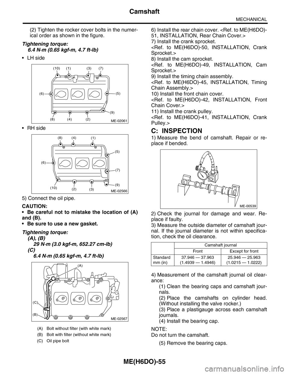
(2) Tighten the rocker cover bolts in the numer-
ical order as shown in the figure.
Tightening torque:
6.4 N·m (0.65 kgf-m, 4.7 ft-lb)
•LH side
•RH side
5) Connect the oil pipe.
CAUTION:
•Be careful not to mistake the location of (A)
and (B).
•Be sure to use a new gasket.
Tightening torque:
(A), (B)
29 N·m (3.0 kgf-m, 652.27 cm-lb)
(C)
6.4 N·m (0.65 kgf-m, 4.7 ft-lb)
6) Install the rear chain cover.
51, INSTALLATION, Rear Chain Cover.>
7) Install the crank sprocket.
Sprocket.>
8) Install the cam sprocket.
Sprocket.>
9) Install the timing chain assembly.
Chain Assembly.>
10) Install the front chain cover.
Chain Cover.>
11) Install the crank pulley.
Pulley.>
C: INSPECTION
1) Measure the bend of camshaft. Repair or re-
place if bended.
2) Check the journal for damage and wear. Re-
place if faulty.
3) Measure the outside diameter of camshaft jour-
nal. If the journal diameter is not within specifica-
tion, check the oil clearance.
4) Measurement of the camshaft journal oil clear-
ance:
(1) Clean the bearing caps and camshaft jour-
nals.
(2) Place the camshafts on cylinder head.
(Without installing the valve rocker.)
(3) Place a plastigauge across each camshaft
journals.
(4) Install the bearing cap.
NOTE:
Do not turn the camshaft.
(5) Remove the bearing caps.
(A) Bolt without filter (with white mark)
(B) Bolt with filter (without white mark)
(C) Oil pipe bolt
ME-02061(2)
(7)(3)(1)(10)
(6)
(8)(4)
(5)
(9)
ME-02566
(8)(4)(1)
(5)
(7)
(9)(3)(2)
(6)
(10)
ME-02567
(A)
(C)
(B)
Camshaft journal
Front Except for front
Standard
mm (in)
37.946 — 37.963
(1.4939 — 1.4946)
25.946 — 25.963
(1.0215 — 1.0222)
ME-00539
Page 1922 of 2453
ME(H6DO)-56
Camshaft
MECHANICAL
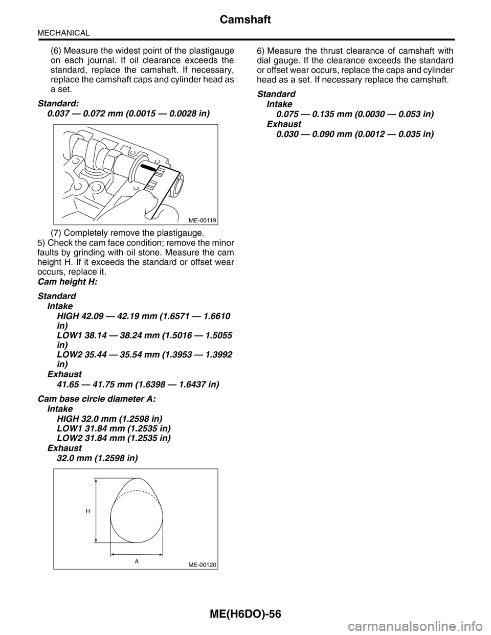
(6) Measure the widest point of the plastigauge
on each journal. If oil clearance exceeds the
standard, replace the camshaft. If necessary,
replace the camshaft caps and cylinder head as
a set.
Standard:
0.037 — 0.072 mm (0.0015 — 0.0028 in)
(7) Completely remove the plastigauge.
5) Check the cam face condition; remove the minor
faults by grinding with oil stone. Measure the cam
height H. If it exceeds the standard or offset wear
occurs, replace it.
Cam height H:
Standard
Intake
HIGH 42.09 — 42.19 mm (1.6571 — 1.6610
in)
LOW1 38.14 — 38.24 mm (1.5016 — 1.5055
in)
LOW2 35.44 — 35.54 mm (1.3953 — 1.3992
in)
Exhaust
41.65 — 41.75 mm (1.6398 — 1.6437 in)
Cam base circle diameter A:
Intake
HIGH 32.0 mm (1.2598 in)
LOW1 31.84 mm (1.2535 in)
LOW2 31.84 mm (1.2535 in)
Exhaust
32.0 mm (1.2598 in)
6) Measure the thrust clearance of camshaft with
dial gauge. If the clearance exceeds the standard
or offset wear occurs, replace the caps and cylinder
head as a set. If necessary replace the camshaft.
Standard
Intake
0.075 — 0.135 mm (0.0030 — 0.053 in)
Exhaust
0.030 — 0.090 mm (0.0012 — 0.035 in)
ME-00119
ME-00120
H
A