Page 1840 of 2453
IG(H6DO)-5
Spark Plug
IGNITION
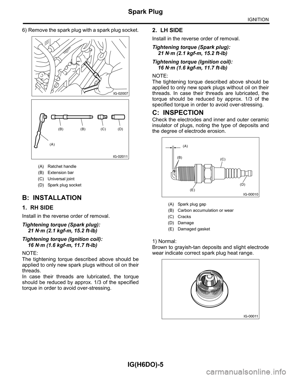
6) Remove the spark plug with a spark plug socket.
B: INSTALLATION
1. RH SIDE
Install in the reverse order of removal.
Tightening torque (Spark plug):
21 N·m (2.1 kgf-m, 15.2 ft-lb)
Tightening torque (Ignition coil):
16 N·m (1.6 kgf-m, 11.7 ft-lb)
NOTE:
The tightening torque described above should be
applied to only new spark plugs without oil on their
threads.
In case their threads are lubricated, the torque
should be reduced by approx. 1/3 of the specified
torque in order to avoid over-stressing.
2. LH SIDE
Install in the reverse order of removal.
Tightening torque (Spark plug):
21 N·m (2.1 kgf-m, 15.2 ft-lb)
Tightening torque (Ignition coil):
16 N·m (1.6 kgf-m, 11.7 ft-lb)
NOTE:
The tightening torque described above should be
applied to only new spark plugs without oil on their
threads. In case their threads are lubricated, the
torque should be reduced by approx. 1/3 of the
specified torque in order to avoid over-stressing.
C: INSPECTION
Check the electrodes and inner and outer ceramic
insulator of plugs, noting the type of deposits and
the degree of electrode erosion.
1) Normal:
Brown to grayish-tan deposits and slight electrode
wear indicate correct spark plug heat range.
(A) Ratchet handle
(B) Extension bar
(C) Universal joint
(D) Spark plug socket
IG-02007
(D)(C)(B)(B)
(A)
IG-02011
(A) Spark plug gap
(B) Carbon accumulation or wear
(C) Cracks
(D) Damage
(E) Damaged gasket
IG-00010
(A)
(B)(C)
(D)
(E)
IG-00011
Page 1855 of 2453
LU(H6DO)-6
Oil Pressure System
LUBRICATION
B: INSPECTION
Step Check Yes No
1CHECK COMBINATION METER.
1) Turn the ignition switch ON. (Engine OFF)
2) Check the warning light of combination
meter.
Does the warning light illumi-
nate?
Go to step 2.Repair or replace
the combination
meter.
4, INSPECTION,
Combination
Meter System.>
2CHECK HARNESS CONNECTOR BETWEEN
COMBINATION METER AND OIL PRES-
SURE SWITCH.
1) Turn the ignition switch to OFF.
2) Disconnect the connector from oil pressure
switch.
3) Turn the ignition switch ON.
4) Measure the voltage of harness between oil
pressure switch connector and chassis ground.
Connector & terminal
(E11) No. 1 (+) — Chassis ground (–):
Is the voltage more than 10 V? Replace the oil
pressure switch.
Go to step 3.
3CHECK COMBINATION METER.
1) Turn the ignition switch to OFF.
2) Remove the combination meter.
3) Measure the resistance of combination
meter.
Te r m i n a l s
(i10) No. 4 — (i77) No. 10:
(i10) No. 3 — (i77) No. 10:
Is the resistance less than 10
Ω?
Replace the har-
ness connector
between combina-
tion meter and oil
pressure switch.
Repair or replace
the combination
meter.
4, INSPECTION,
Combination
Meter System.>
Page 1856 of 2453
LU(H6DO)-7
Engine Oil
LUBRICATION
3. Engine Oil
A: INSPECTION
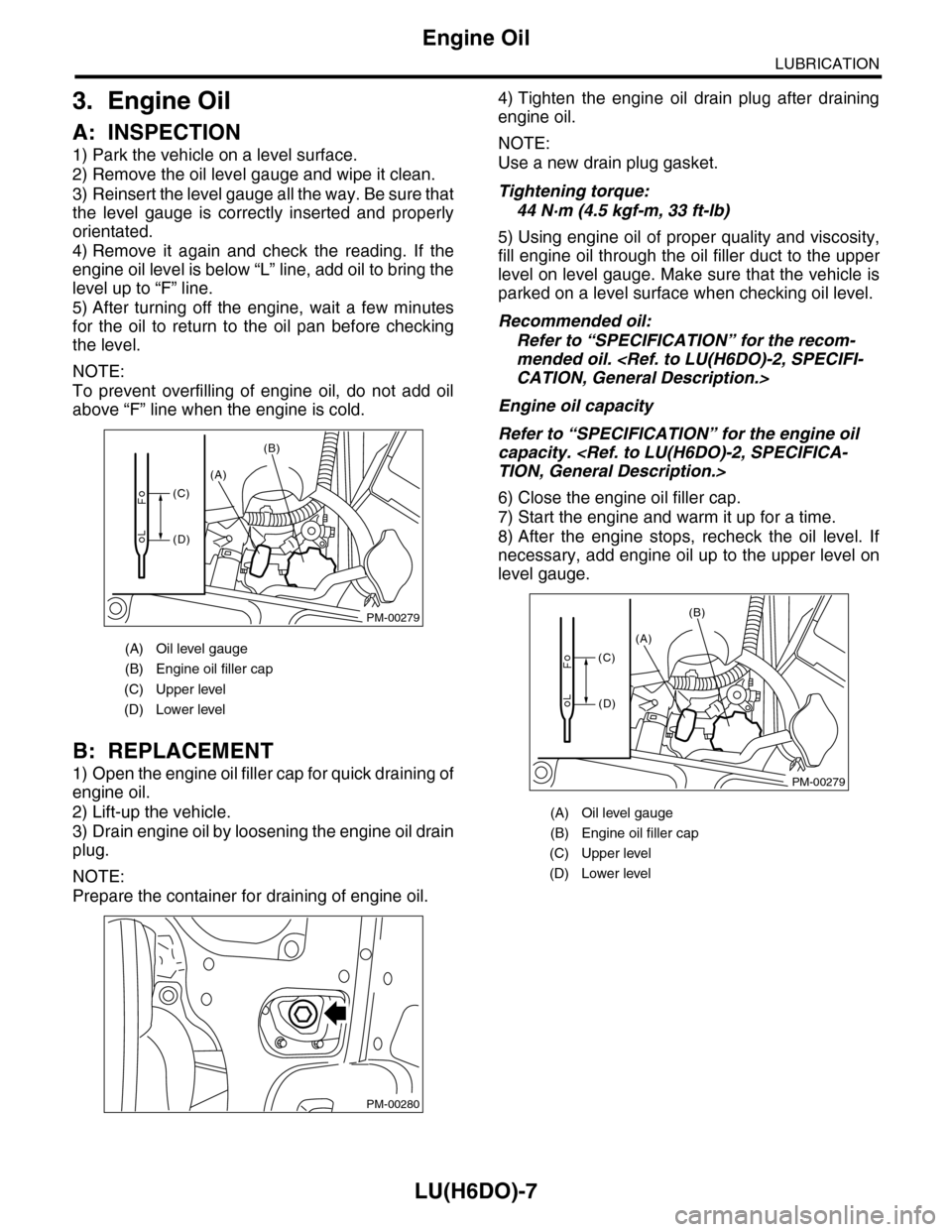
1) Park the vehicle on a level surface.
2) Remove the oil level gauge and wipe it clean.
3) Reinsert the level gauge all the way. Be sure that
the level gauge is correctly inserted and properly
orientated.
4) Remove it again and check the reading. If the
engine oil level is below “L” line, add oil to bring the
level up to “F” line.
5) After turning off the engine, wait a few minutes
for the oil to return to the oil pan before checking
the level.
NOTE:
To prevent overfilling of engine oil, do not add oil
above “F” line when the engine is cold.
B: REPLACEMENT
1) Open the engine oil filler cap for quick draining of
engine oil.
2) Lift-up the vehicle.
3) Drain engine oil by loosening the engine oil drain
plug.
NOTE:
Prepare the container for draining of engine oil.
4) Tighten the engine oil drain plug after draining
engine oil.
NOTE:
Use a new drain plug gasket.
Tightening torque:
44 N·m (4.5 kgf-m, 33 ft-lb)
5) Using engine oil of proper quality and viscosity,
fill engine oil through the oil filler duct to the upper
level on level gauge. Make sure that the vehicle is
parked on a level surface when checking oil level.
Recommended oil:
Refer to “SPECIFICATION” for the recom-
mended oil.
CATION, General Description.>
Engine oil capacity
Refer to “SPECIFICATION” for the engine oil
capacity.
TION, General Description.>
6) Close the engine oil filler cap.
7) Start the engine and warm it up for a time.
8) After the engine stops, recheck the oil level. If
necessary, add engine oil up to the upper level on
level gauge.
(A) Oil level gauge
(B) Engine oil filler cap
(C) Upper level
(D) Lower level
PM-00279
(A)
(B)
(C)
(D)
PM-00280
(A) Oil level gauge
(B) Engine oil filler cap
(C) Upper level
(D) Lower level
PM-00279
(A)
(B)
(C)
(D)
Page 1858 of 2453
LU(H6DO)-9
Oil Pump
LUBRICATION
C: INSPECTION
1. TIP CLEARANCE
Measure the tip clearance of rotors. If the clearance
exceeds specification, replace the rotors as a
matched set.
Tip clearance:
Specification
0.04 — 0.14 mm (0.0016 — 0.0055 in)
2. CASE CLEARANCE
Measure the clearance between the outer rotor and
rear chain cover rotor housing. If the clearance ex-
ceeds the standard value, replace the outer rotor.
Case clearance:
Specification
0.110 — 0.175 mm (0.0043 — 0.0069 in)
3. SIDE CLEARANCE
Measure the clearance between oil pump inner ro-
tor and rear chain cover. If the clearance exceeds
specification, replace the rotors as a matched set.
Side clearance:
Specification
0.020 — 0.046 mm (0.0008 — 0.0018 in)
4. OIL PUMP CASE
Check the worn shaft hole, clogged oil passage,
crank and other parts for faults.
LU-02014
LU-02015
LU-02016
Page 1859 of 2453
LU(H6DO)-10
Oil Pump Relief Valve
LUBRICATION
5. Oil Pump Relief Valve
A: REMOVAL
1. REAR CHAIN COVER SIDE
Oil pump relief valve is integrated into oil pump cov-
er as one unit; therefore, refer to “Oil Pump” for re-
moval procedure.
REMOVAL, Oil Pump.>
2. OIL PAN UPPER SIDE
1) Remove the oil pan.
MOVAL, Oil Pan and Strainer.>
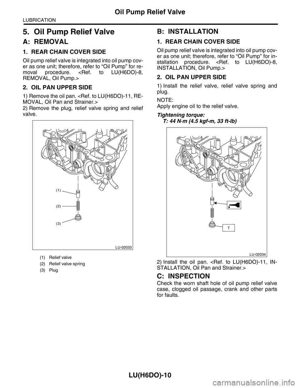
2) Remove the plug, relief valve spring and relief
valve.
B: INSTALLATION
1. REAR CHAIN COVER SIDE
Oil pump relief valve is integrated into oil pump cov-
er as one unit; therefore, refer to “Oil Pump” for in-
stallation procedure.
INSTALLATION, Oil Pump.>
2. OIL PAN UPPER SIDE
1) Install the relief valve, relief valve spring and
plug.
NOTE:
Apply engine oil to the relief valve.
Tightening torque:
T: 44 N·m (4.5 kgf-m, 33 ft-lb)
2) Install the oil pan.
STALLATION, Oil Pan and Strainer.>
C: INSPECTION
Check the worn shaft hole of oil pump relief valve
case, clogged oil passage, crank and other parts
for faults.
(1) Relief valve
(2) Relief valve spring
(3) Plug
(1)
LU-02033
(2)
(3)
LU-02034
T
Page 1861 of 2453
LU(H6DO)-12
Oil Pan and Strainer
LUBRICATION
3) Tighten the oil pan lower installing bolts in the
numerical order as shown in the figure.
Tightening torque:
6.4 N·m (0.65 kgf-m, 4.7 ft-lb)
4) Install the under cover.
5) Refill the engine oil.
SPECTION, Engine Oil.>
C: INSPECTION
Visually check that the oil pan, oil strainer and oil
strainer stay are not damaged.
(1)(2)
(3)
(4)
(5)
(6)
(7)(8)(9)
(10)
(11)
(12)
(13)
(14)
(15)
LU-00126
Page 1863 of 2453
LU(H6DO)-14
Engine Oil Filter
LUBRICATION
8. Engine Oil Filter
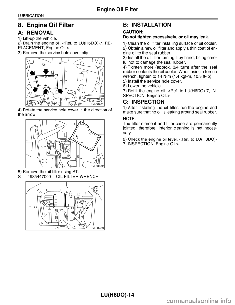
A: REMOVAL
1) Lift-up the vehicle.
2) Drain the engine oil.
PLACEMENT, Engine Oil.>
3) Remove the service hole cover clip.
4) Rotate the service hole cover in the direction of
the arrow.
5) Remove the oil filter using ST.
ST 4985447000 OIL FILTER WRENCH
B: INSTALLATION
CAUTION:
Do not tighten excessively, or oil may leak.
1) Clean the oil filter installing surface of oil cooler.
2) Obtain a new oil filter and apply a thin coat of en-
gine oil to the seal rubber.
3) Install the oil filter turning it by hand, being care-
ful not to damage the seal rubber.
4) Tighten more (approx. 3/4 turn) after the seal
rubber contacts the oil cooler. When using a torque
wrench, tighten to 14 N·m (1.4 kgf-m, 10.3 ft-lb).
5) Install the service hole cover.
6) Lower the vehicle.
7) Refill the engine oil.
SPECTION, Engine Oil.>
C: INSPECTION
1) After installing the oil filter, run the engine and
make sure that no oil is leaking around seal rubber.
NOTE:
The filter element and filter case are permanently
jointed; therefore, interior cleaning is not neces-
sary.
2) Check the engine oil level.
7, INSPECTION, Engine Oil.>
PM-00281
PM-00282
PM-00283
Page 1865 of 2453
LU(H6DO)-16
Oil Cooler
LUBRICATION
3) Connect the water hose.
4) Install the water pipe onto engine.
Tightening torque:
6.4 N·m (0.65 kgf-m, 4.7 ft-lb)
5) Refill the engine oil.
PLACEMENT, Engine Oil.>
6) Fill engine coolant.
FILLING OF ENGINE COOLANT, REPLACE-
MENT, Engine Coolant.>
7) Check the engine oil level.
7, INSPECTION, Engine Oil.>
C: INSPECTION
1) Check that coolant passages are not clogged
using an compressed air.
2) Check that the oil pan upper and O-ring installing
surface of oil filter are not damaged.
LU-00133
LU-00132