Page 1988 of 2453
PM-5
Schedule
PERIODIC MAINTENANCE SERVICES
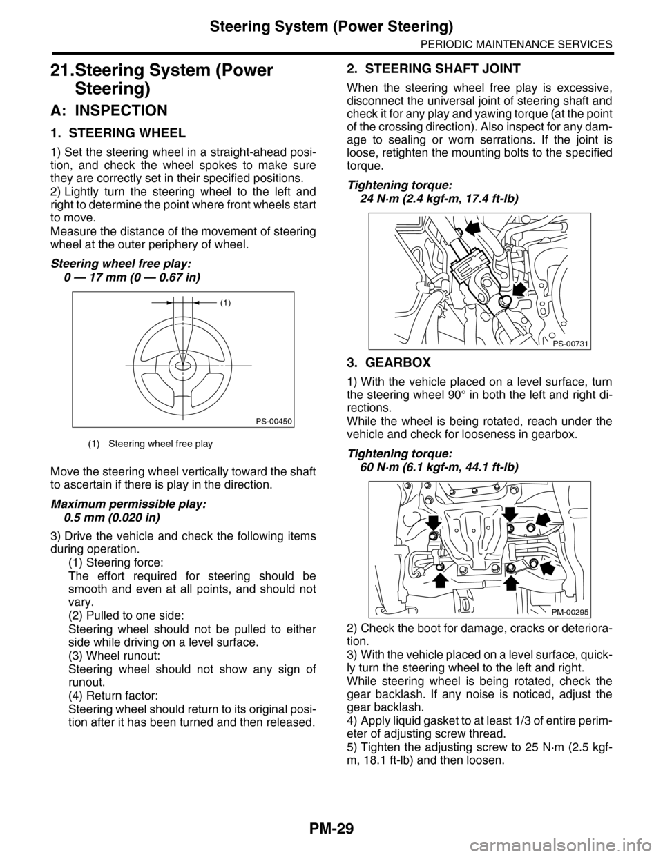
B: MAINTENANCE SCHEDULE 2
ItemMaintenance
interval
Repeat short
distance drive
Repeat
rough/muddy
road drive
Extremely
cold weather
area
Salt or other
corrosive
used or
coastal area
High humid-
ity or moun-
tain area
Repeat tow-
ing trailer
Engine oil 3.75 months R R R
6,000 km
3,750 miles
Engine oil filter 3.75 months R R R
6,000 km
3,750 miles
Fuel line 7.5 months I
12,000 km
7,500 miles
Automatic trans-
mission fluid
15 months R
24,000 km
15,000 miles
Fr o nt & r ea r
differential oil
15 months R
24,000 km
15,000 miles
Brake line 7.5 months I
12,000 km
7,500 miles
Brake fluid 15 months R
24,000 km
15,000 miles
Disc brake pad
and disc
15 months I I I I
24,000 km
15,000 miles
Par king brake 15 months I I I I
24,000 km
15,000 miles
Suspension 7.5 months I I I
12,000 km
7,500 miles
Axle boots and
joints
7.5 months I I I I I
12,000 km
7,500 miles
Steering system
(Power steering)
7.5 months I I I
12,000 km
7,500 miles
Page 1993 of 2453
PM-10
V-belt
PERIODIC MAINTENANCE SERVICES
6. V-belt
A: INSPECTION
1) Replace the belts if cracks, fraying or wear are
found.
2) Make sure that the V-belt automatic belt tension
indicator (A) is within the range of its use limit (D).
B: REPLACEMENT
1) Remove the cover.
2) Fit the tool to the belt tensioner mounting bolt.
3) Turn the tool in the direction of the arrow, and
loosen the V-belt to remove it.
4) Install in the reverse order of removal.
(A) Indicator
(B) Generator
(C) Power steering oil pump
(D) Service limit
(B)
(A)
(D)
(C)
ME-00475
(1) Power steering oil pump
(2) Belt tension adjuster
(3) Crank pulley
(4) A/C compressor
(5) Belt idler
(6) Generator
PM-00301
(1)(6)
(4)
(5)(2)
(3)ME-00474
Page 2012 of 2453

PM-29
Steering System (Power Steering)
PERIODIC MAINTENANCE SERVICES
21.Steering System (Power
Steering)
A: INSPECTION
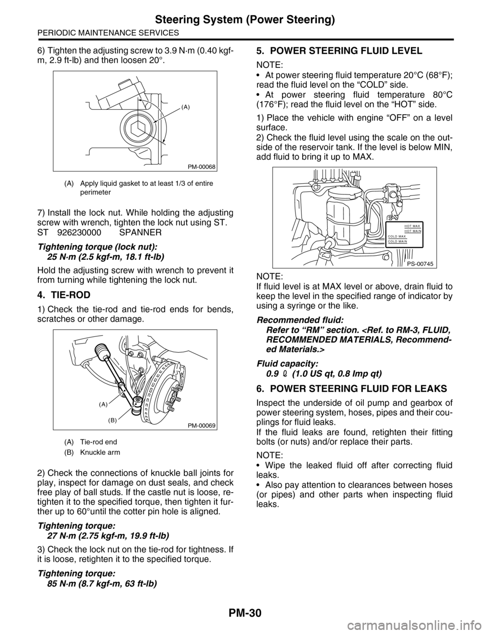
1. STEERING WHEEL
1) Set the steering wheel in a straight-ahead posi-
tion, and check the wheel spokes to make sure
they are correctly set in their specified positions.
2) Lightly turn the steering wheel to the left and
right to determine the point where front wheels start
to move.
Measure the distance of the movement of steering
wheel at the outer periphery of wheel.
Steering wheel free play:
0 — 17 mm (0 — 0.67 in)
Move the steering wheel vertically toward the shaft
to ascertain if there is play in the direction.
Maximum permissible play:
0.5 mm (0.020 in)
3) Drive the vehicle and check the following items
during operation.
(1) Steering force:
The effort required for steering should be
smooth and even at all points, and should not
vary.
(2) Pulled to one side:
Steering wheel should not be pulled to either
side while driving on a level surface.
(3) Wheel runout:
Steering wheel should not show any sign of
runout.
(4) Return factor:
Steering wheel should return to its original posi-
tion after it has been turned and then released.
2. STEERING SHAFT JOINT
When the steering wheel free play is excessive,
disconnect the universal joint of steering shaft and
check it for any play and yawing torque (at the point
of the crossing direction). Also inspect for any dam-
age to sealing or worn serrations. If the joint is
loose, retighten the mounting bolts to the specified
torque.
Tightening torque:
24 N·m (2.4 kgf-m, 17.4 ft-lb)
3. GEARBOX
1) With the vehicle placed on a level surface, turn
the steering wheel 90° in both the left and right di-
rections.
While the wheel is being rotated, reach under the
vehicle and check for looseness in gearbox.
Tightening torque:
60 N·m (6.1 kgf-m, 44.1 ft-lb)
2) Check the boot for damage, cracks or deteriora-
tion.
3) With the vehicle placed on a level surface, quick-
ly turn the steering wheel to the left and right.
While steering wheel is being rotated, check the
gear backlash. If any noise is noticed, adjust the
gear backlash.
4) Apply liquid gasket to at least 1/3 of entire perim-
eter of adjusting screw thread.
5) Tighten the adjusting screw to 25 N·m (2.5 kgf-
m, 18.1 ft-lb) and then loosen.
(1) Steering wheel free play
(1)
PS-00450
PS-00731
PM-00295
Page 2013 of 2453

PM-30
Steering System (Power Steering)
PERIODIC MAINTENANCE SERVICES
6) Tighten the adjusting screw to 3.9 N·m (0.40 kgf-
m, 2.9 ft-lb) and then loosen 20°.
7) Install the lock nut. While holding the adjusting
screw with wrench, tighten the lock nut using ST.
ST 926230000 SPANNER
Tightening torque (lock nut):
25 N·m (2.5 kgf-m, 18.1 ft-lb)
Hold the adjusting screw with wrench to prevent it
from turning while tightening the lock nut.
4. TIE-ROD
1) Check the tie-rod and tie-rod ends for bends,
scratches or other damage.
2) Check the connections of knuckle ball joints for
play, inspect for damage on dust seals, and check
free play of ball studs. If the castle nut is loose, re-
tighten it to the specified torque, then tighten it fur-
ther up to 60°until the cotter pin hole is aligned.
Tightening torque:
27 N·m (2.75 kgf-m, 19.9 ft-lb)
3) Check the lock nut on the tie-rod for tightness. If
it is loose, retighten it to the specified torque.
Tightening torque:
85 N·m (8.7 kgf-m, 63 ft-lb)
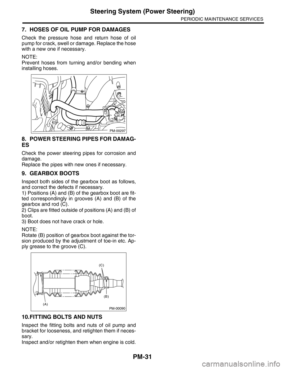
5. POWER STEERING FLUID LEVEL
NOTE:
•At power steering fluid temperature 20°C (68°F);
read the fluid level on the “COLD” side.
•At power steering fluid temperature 80°C
(176°F); read the fluid level on the “HOT” side.
1) Place the vehicle with engine “OFF” on a level
surface.
2) Check the fluid level using the scale on the out-
side of the reservoir tank. If the level is below MIN,
add fluid to bring it up to MAX.
NOTE:
If fluid level is at MAX level or above, drain fluid to
keep the level in the specified range of indicator by
using a syringe or the like.
Recommended fluid:
Refer to “RM” section.
RECOMMENDED MATERIALS, Recommend-
ed Materials.>
Fluid capacity:
0.9 2 (1.0 US qt, 0.8 Imp qt)
6. POWER STEERING FLUID FOR LEAKS
Inspect the underside of oil pump and gearbox of
power steering system, hoses, pipes and their cou-
plings for fluid leaks.
If the fluid leaks are found, retighten their fitting
bolts (or nuts) and/or replace their parts.
NOTE:
•Wipe the leaked fluid off after correcting fluid
leaks.
•Also pay attention to clearances between hoses
(or pipes) and other parts when inspecting fluid
leaks.
(A) Apply liquid gasket to at least 1/3 of entire
perimeter
(A) Tie-rod end
(B) Knuckle arm
PM-00068
(A)
PM-00069
(A)
(B)
PS-00745
HOT MAXHOT MAINCOLD MAXCOLD MAIN
Page 2014 of 2453

PM-31
Steering System (Power Steering)
PERIODIC MAINTENANCE SERVICES
7. HOSES OF OIL PUMP FOR DAMAGES
Check the pressure hose and return hose of oil
pump for crack, swell or damage. Replace the hose
with a new one if necessary.
NOTE:
Prevent hoses from turning and/or bending when
installing hoses.
8. POWER STEERING PIPES FOR DAMAG-
ES
Check the power steering pipes for corrosion and
damage.
Replace the pipes with new ones if necessary.
9. GEARBOX BOOTS
Inspect both sides of the gearbox boot as follows,
and correct the defects if necessary.
1) Positions (A) and (B) of the gearbox boot are fit-
ted correspondingly in grooves (A) and (B) of the
gearbox and rod (C).
2) Clips are fitted outside of positions (A) and (B) of
boot.
3) Boot does not have crack or hole.
NOTE:
Rotate (B) position of gearbox boot against the tor-
sion produced by the adjustment of toe-in etc. Ap-
ply grease to the groove (C).
10.FITTING BOLTS AND NUTS
Inspect the fitting bolts and nuts of oil pump and
bracket for looseness, and retighten them if neces-
sary.
Inspect and/or retighten them when engine is cold.
PM-00297
PM-00090
(C)
(B)
(A)
Page 2305 of 2453
WI-21
Power Supply Circuit
WIRING SYSTEM
FB-37 Body integrated unit
FB-38 ECM
TCM
Fuel pump relay
FB-39 Airbag control module
FB-41 Airbag control module
FB-42 Power window relay
FB-44 VDC control module
Steering angle sensor
Ya w r a t e s e n s o r
FB-45 A/C control panel
Rear cooler relay
FB-46 A/C relay
FRESH/RECIRC actuator
Auto A/C control module
Pressure switch
Blower fan relay
FB-47 Occupant detection control module
FB-48 TPM control module
FB-49 Impact sensor
TV monitor
ACC -1 Front washer motor
ST-1 ECM
Starter relay
No. Load
Page 2316 of 2453

WI-32
Engine Electrical System
WIRING SYSTEM
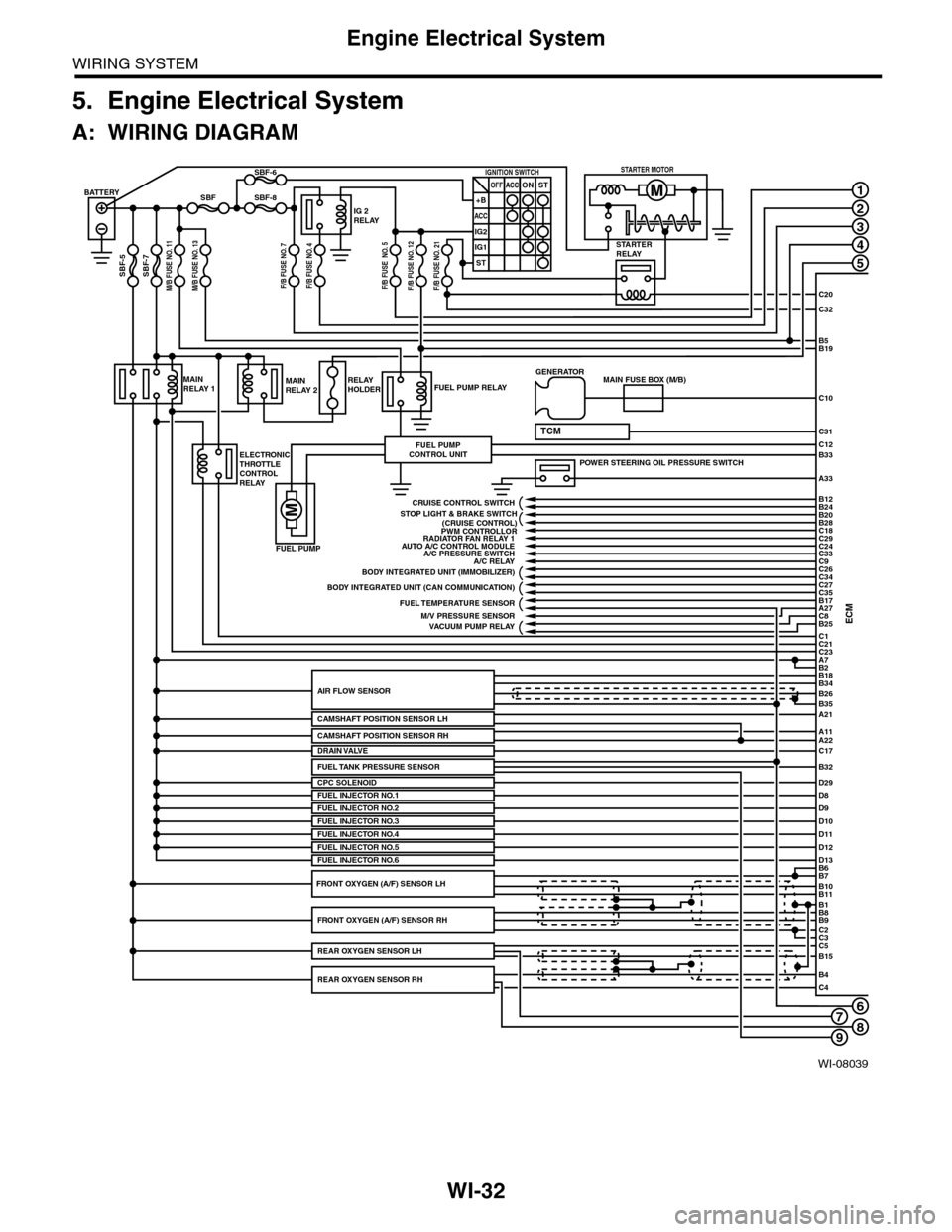
5. Engine Electrical System
A: WIRING DIAGRAM
WI-08039
678
1
2
3
4
5
C20
C32
C31
B5B19
B33
A33
C10
ECMC1B25C8A27
C21C23A7
D29
B2
BATTERY
M/B FUSE NO. 11SBF-7
SBF
SBF-5
SBF-8
SBF-6
STARTERRELAY
IG 2RELAY
IGNITION SWITCHOFF+B
ACC
IG2
IG1
ACCONST
ST
STARTER MOTOR
MAINRELAY 1
ELECTRONICTHROTTLECONTROLRELAY
FUEL PUMP RELAY
FUEL PUMP
FUEL PUMPCONTROL UNIT
MAINRELAY 2RELAYHOLDER
A21
A11A22
B34
B35
B7B6
B11B10
B9B8
C2
B26AIR FLOW SENSOR
CAMSHAFT POSITION SENSOR LH
CPC SOLENOID
B1
C3C5B15
B4C4
POWER STEERING OIL PRESSURE SWITCH
C12
MAIN FUSE BOX (M/B)GENERATOR
B18
TCM
D8FUEL INJECTOR NO.1D9D10D11
PWM CONTROLLORAUTO A/C CONTROL MODULE
A/C RELAY
BODY INTEGRATED UNIT (CAN COMMUNICATION)
FUEL TEMPERATURE SENSOR
VACUUM PUMP RELAY
BODY INTEGRATED UNIT (IMMOBILIZER)
C18C29C24C33
C27
B24B12
B20B28
C26C34
C35B17
CRUISE CONTROL SWITCH
FUEL INJECTOR NO.2FUEL INJECTOR NO.3
C17DRAIN VALVE
FUEL INJECTOR NO.4D12D13FUEL INJECTOR NO.5FUEL INJECTOR NO.6
FRONT OXYGEN (A/F) SENSOR RH
REAR OXYGEN SENSOR RH
REAR OXYGEN SENSOR LH
FRONT OXYGEN (A/F) SENSOR LH
A/C PRESSURE SWITCH
M/V PRESSURE SENSOR
RADIATOR FAN RELAY 1
STOP LIGHT & BRAKE SWITCH(CRUISE CONTROL)
C9
FUEL TANK PRESSURE SENSORB32
M/B FUSE NO. 13F/B FUSE NO. 7F/B FUSE NO. 4F/B FUSE NO. 5F/B FUSE NO. 12F/B FUSE NO. 21
CAMSHAFT POSITION SENSOR RH
9
Page 2327 of 2453
WI-43
Engine Electrical System
WIRING SYSTEM
WI-08050
E/G-10E/G-10
D:B137
D29
RG
A6
YW
31E28
E76
E77
A19
LY
YWYGE4
B:B135A:B134ECM
CPCSOLENOID
E2
B21
A33
PB
LYYW
LYYW
21
15
RGYL
(BLUE)E4
12
B21
12345678910 1112 13 14 15 16 17 18 19 20 21 2223 24 25 26 27 28 29 30 31 32 33
34 3542 4336 3738 39
48 4950 5152 5354
40 41444546 47
YG
YG
B30
YG
LGYG
YGV
B424
JPINTCONNECTORE/G-07M
B424
34561278
D: B137
85610 11 12 13 14 157213416
3019 20 2228 29
91718 2521 23 243126 27
E/G-12V
YG
YG
6
E/G-09R
LY
2
RG
RG
2
YL
YL
3
E/G-07L
E/G-06I
E/G-06J
E/G-01A
POWER STEERING OILPRESSURE SWITCH
E19PB
9
PB
PB
E/G-09S
E/G-09T
41
RG
RG
197
PYW
YGYW
20
LY
LY
A29
P
INTAKE MANIFOLDPRESSURE SENSOR
E28
123
(BLACK)(BLACK)E77
134562
(DARK GRAY)
A:B134
85610 11 12 13 14 157213416
3019 20 2228 29
91718252123 24323126 2733 34
*1
*1
*1
*1
*1*1
*1 : TERMINAL NO. OPTIONAL ARRANGEMENT
B:B135
5672134
29
101112131415252416
30
98171819202821222332312627333435