Page 1871 of 2453
ME(H6DO)-5
General Description
MECHANICAL
B: COMPONENT
1. V-BELT
(1) V-belt (6) Generator plateTightening torque: N·m (kgf-m, ft-lb)
(2) Collector cover bracket (7) A/C compressor stayT1: 6.4 (0.65, 4.7)
(3) Belt tension adjuster ASSY (8) Idler pulleyT2: 20 (2.0, 14)
(4) Power steering pump bracket (9) Idler pulley coverT3: 25 (2.5, 18)
(5) GeneratorT4: 33 (3.4, 24.3)
Page 1897 of 2453
ME(H6DO)-31
V-belt
MECHANICAL
9. V-belt
A: REMOVAL
1) Install the tool to belt tension adjuster assembly
installation bolt.
2) Rotate the tool clockwise and loosen the V-belt
to remove.
3) Remove the V-belt cover.
B: INSTALLATION
Install in the reverse order of removal.
C: INSPECTION
1) Replace the V-belt, if cracks, fraying or wear is
found.
2) Make sure that the V-belt automatic belt tension
indicator (A) is within the range (D).
(1) Power steering oil pump pulley
(2) Belt tension adjuster ASSY
(3) Crank pulley
(4) A/C compressor
(5) Belt idler
(6) Generator
ME-00473
(1)(6)
(4)
(5)(2)
(3)ME-00474
(A) Indicator
(B) Generator
(C) Power steering oil pump pulley
(D) Service limit
(B)
(A)
(D)
(C)
ME-00475
Page 1898 of 2453
ME(H6DO)-32
Engine Assembly
MECHANICAL
10.Engine Assembly
A: REMOVAL
1) Set the vehicle on a lift.
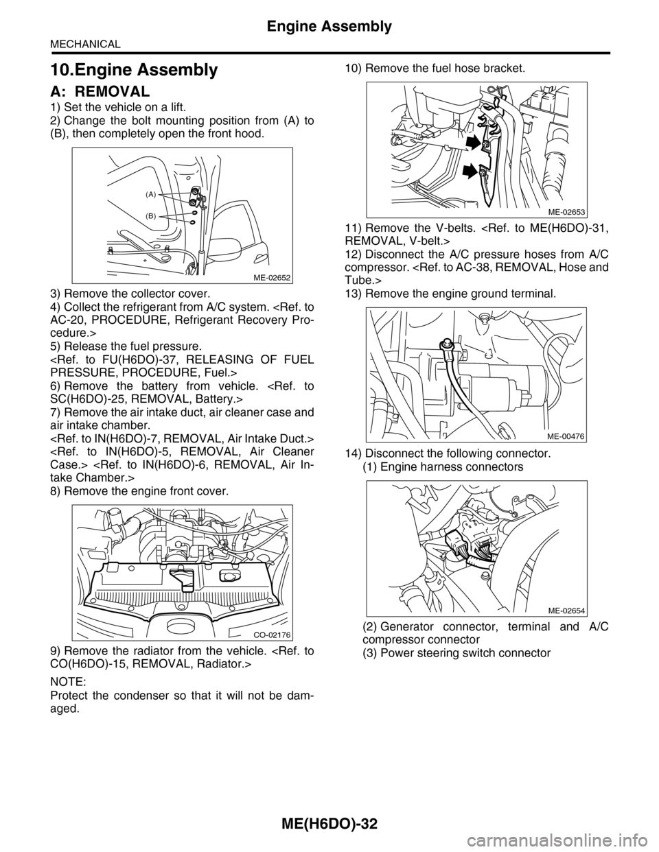
2) Change the bolt mounting position from (A) to
(B), then completely open the front hood.
3) Remove the collector cover.
4) Collect the refrigerant from A/C system.
AC-20, PROCEDURE, Refrigerant Recovery Pro-
cedure.>
5) Release the fuel pressure.
PRESSURE, PROCEDURE, Fuel.>
6) Remove the battery from vehicle.
SC(H6DO)-25, REMOVAL, Battery.>
7) Remove the air intake duct, air cleaner case and
air intake chamber.
Case.>
take Chamber.>
8) Remove the engine front cover.
9) Remove the radiator from the vehicle.
CO(H6DO)-15, REMOVAL, Radiator.>
NOTE:
Protect the condenser so that it will not be dam-
aged.
10) Remove the fuel hose bracket.
11) Remove the V-belts.
REMOVAL, V-belt.>
12) Disconnect the A/C pressure hoses from A/C
compressor.
Tube.>
13) Remove the engine ground terminal.
14) Disconnect the following connector.
(1) Engine harness connectors
(2) Generator connector, terminal and A/C
compressor connector
(3) Power steering switch connector
ME-02652
(A)
(B)
CO-02176
ME-02653
ME-00476
ME-02654
Page 1899 of 2453
ME(H6DO)-33
Engine Assembly
MECHANICAL
15) Disconnect the following hoses.
(1) Brake booster vacuum hose
(2) Heater inlet and outlet hoses
16) Remove the power steering pump with the
bracket.
NOTE:
Do not disconnect the hose and pipe from the pow-
er steering pump body.
17) Remove the reservoir tank with the bracket.
NOTE:
Do not disconnect the hose from the reservoir tank
body.
18) Suspend the power steering pump using wire,
etc.
19) Remove the bolts which hold the vacuum pump
bracket to the engine and transmission.
20) Lift-up the vehicle.
21) Remove the front exhaust pipe.
Pipe.>
NOTE:
Be careful not to let the front exhaust pipe interfere
with water pipes on engine side.
22) Remove the ground cable.
ME-02655
ME-02656
ME-02657
ME-02658
ME-02659
ME-02027
Page 1903 of 2453
ME(H6DO)-37
Engine Assembly
MECHANICAL
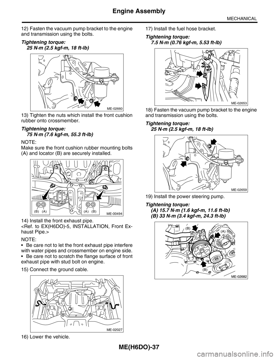
12) Fasten the vacuum pump bracket to the engine
and transmission using the bolts.
Tightening torque:
25 N·m (2.5 kgf-m, 18 ft-lb)
13) Tighten the nuts which install the front cushion
rubber onto crossmember.
Tightening torque:
75 N·m (7.6 kgf-m, 55.3 ft-lb)
NOTE:
Make sure the front cushion rubber mounting bolts
(A) and locator (B) are securely installed.
14) Install the front exhaust pipe.
haust Pipe.>
NOTE:
•Be care not to let the front exhaust pipe interfere
with water pipes and crossmember on engine side.
•Be care not to scratch the flange surface of front
exhaust pipe with stud bolt on engine.
15) Connect the ground cable.
16) Lower the vehicle.
17) Install the fuel hose bracket.
Tightening torque:
7.5 N·m (0.76 kgf-m, 5.53 ft-lb)
18) Fasten the vacuum pump bracket to the engine
and transmission using the bolts.
Tightening torque:
25 N·m (2.5 kgf-m, 18 ft-lb)
19) Install the power steering pump.
Tightening torque:
(A) 15.7 N·m (1.6 kgf-m, 11.6 ft-lb)
(B) 33 N·m (3.4 kgf-m, 24.3 ft-lb)
ME-02660
(A)(B)(B)(A)ME-00494
ME-02027
ME-02653
ME-02659
Page 1904 of 2453
ME(H6DO)-38
Engine Assembly
MECHANICAL
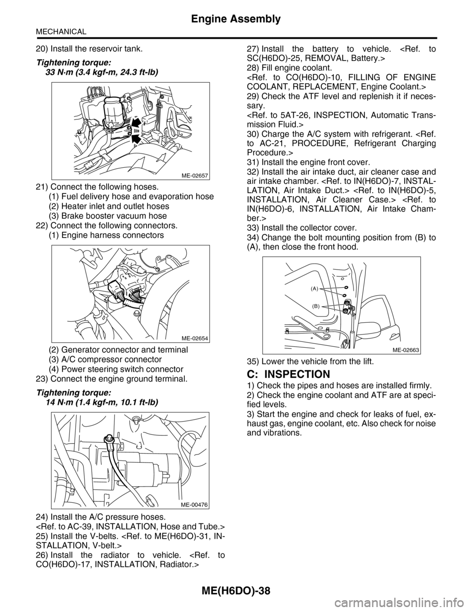
20) Install the reservoir tank.
Tightening torque:
33 N·m (3.4 kgf-m, 24.3 ft-lb)
21) Connect the following hoses.
(1) Fuel delivery hose and evaporation hose
(2) Heater inlet and outlet hoses
(3) Brake booster vacuum hose
22) Connect the following connectors.
(1) Engine harness connectors
(2) Generator connector and terminal
(3) A/C compressor connector
(4) Power steering switch connector
23) Connect the engine ground terminal.
Tightening torque:
14 N·m (1.4 kgf-m, 10.1 ft-lb)
24) Install the A/C pressure hoses.
25) Install the V-belts.
STALLATION, V-belt.>
26) Install the radiator to vehicle.
CO(H6DO)-17, INSTALLATION, Radiator.>
27) Install the battery to vehicle.
SC(H6DO)-25, REMOVAL, Battery.>
28) Fill engine coolant.
COOLANT, REPLACEMENT, Engine Coolant.>
29) Check the ATF level and replenish it if neces-
sary.
mission Fluid.>
30) Charge the A/C system with refrigerant.
to AC-21, PROCEDURE, Refrigerant Charging
Procedure.>
31) Install the engine front cover.
32) Install the air intake duct, air cleaner case and
air intake chamber.
LATION, Air Intake Duct.>
INSTALLATION, Air Cleaner Case.>
IN(H6DO)-6, INSTALLATION, Air Intake Cham-
ber.>
33) Install the collector cover.
34) Change the bolt mounting position from (B) to
(A), then close the front hood.
35) Lower the vehicle from the lift.
C: INSPECTION
1) Check the pipes and hoses are installed firmly.
2) Check the engine coolant and ATF are at speci-
fied levels.
3) Start the engine and check for leaks of fuel, ex-
haust gas, engine coolant, etc. Also check for noise
and vibrations.
ME-02657
ME-02654
ME-00476
ME-02663
(A)
(B)
Page 1986 of 2453
PM-3
Schedule
PERIODIC MAINTENANCE SERVICES
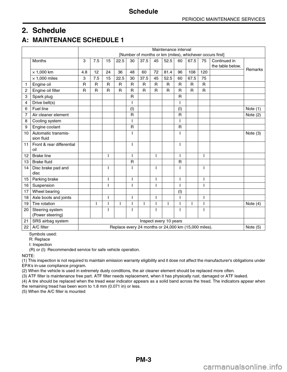
2. Schedule
A: MAINTENANCE SCHEDULE 1
Symbols used:
R: Replace
I: Inspection
(R) or (I): Recommended service for safe vehicle operation.
NOTE:(1) This inspection is not required to maintain emission warranty eligibility and it dose not affect the manufacturer's obligations under
EPA's in-use compliance program.
(2) When the vehicle is used in extremely dusty conditions, the air cleaner element should be replaced more often.
(3) ATF filter is maintenance free part. ATF filter needs replacement, when it has physically rust, damaged or ATF leaked.
(4) A tire should be replaced when the tread wear indicator appears as a solid band across the tread. The indicators appear when
the remaining tread has been worn to 1.8 mm (0.071 in) or less.
(5) When the A/C filter is mounted
Maintenance interval
[Number of months or km (miles), whichever occurs first]
Months 3 7.51522.53037.54552.56067.575Continued in
the table below.Remarks× 1,000 km 4.8 12 24 36 48 60 72 81.4 96 108 120
× 1,000 miles 3 7.5 15 22.5 30 37.5 45 52.5 60 67.5 75
1Engine oil R R R R R R R R R R R
2Engine oil filter R R R R R R R R R R R
3Spark plug R R
4Drive belt(s) I I
6Fuel line (I) (I) Note (1)
7Air cleaner element R R Note (2)
8Cooling system I I
9Engine coolant R R
10 Automatic transmis-
sion fluid
I I Note (3)
11 Front & rear differential
oil
I I
12 Brake line I I I I I
13 Brake fluid R R
14 Disc brake pad and
disc
I I I I I
15 Parking brake I I I I I
16 Suspension I I I I I
17 Wheel bearing (I)
18 Axle boots and joints I I I I I
19 Tire rotation I I I I I I I I I I Note (4)
20 Steering system
(Power steering)
I I I I I
21 SRS airbag system Inspect every 10 years
22 A/C filter Replace every 24 months or 24,000 km (15,000 miles). Note (5)
Page 1987 of 2453
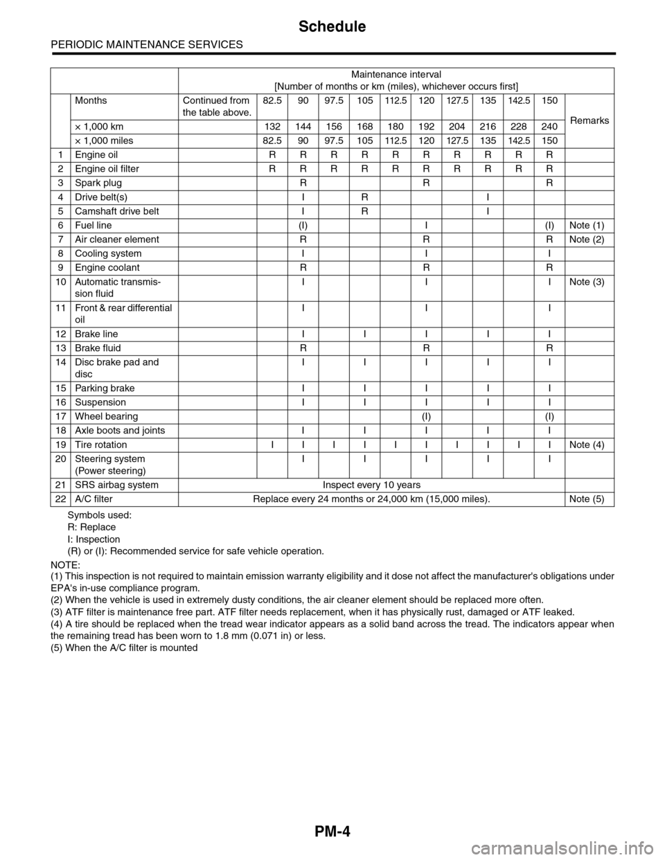
PM-4
Schedule
PERIODIC MAINTENANCE SERVICES
Symbols used:
R: Replace
I: Inspection
(R) or (I): Recommended service for safe vehicle operation.
NOTE:(1) This inspection is not required to maintain emission warranty eligibility and it dose not affect the manufacturer's obligations under
EPA's in-use compliance program.
(2) When the vehicle is used in extremely dusty conditions, the air cleaner element should be replaced more often.
(3) ATF filter is maintenance free part. ATF filter needs replacement, when it has physically rust, damaged or ATF leaked.
(4) A tire should be replaced when the tread wear indicator appears as a solid band across the tread. The indicators appear when
the remaining tread has been worn to 1.8 mm (0.071 in) or less.
(5) When the A/C filter is mounted
Maintenance interval
[Number of months or km (miles), whichever occurs first]
Months Continued from
the table above.
82.5 90 97.5 105112.5120127.5135142.5150
Remarks× 1,000 km 132 144 156 168 180 192 204 216 228 240
× 1,000 miles 82.5 90 97.5 105112.5120127.5135142.5150
1Engine oil R R R R R R R R R R
2Engine oil filter R R R R R R R R R R
3Spark plug R R R
4Drive belt(s) I R I
5Camshaft drive belt I R I
6Fuel line (I) I (I) Note (1)
7Air cleaner element R R R Note (2)
8Cooling system I I I
9Engine coolant R R R
10 Automatic transmis-
sion fluid
I I INote (3)
11 Front & rear differential
oil
I I I
12 Brake line I I I I I
13 Brake fluid R R R
14 Disc brake pad and
disc
I I I I I
15 Parking brake I I I I I
16 Suspension I I I I I
17 Wheel bearing (I) (I)
18 Axle boots and joints I I I I I
19 Tire rotation I I I I I I I I I I Note (4)
20 Steering system
(Power steering)
I I I I I
21 SRS airbag system Inspect every 10 years
22 A/C filter Replace every 24 months or 24,000 km (15,000 miles). Note (5)