2009 SUBARU TRIBECA power steering
[x] Cancel search: power steeringPage 1006 of 2453
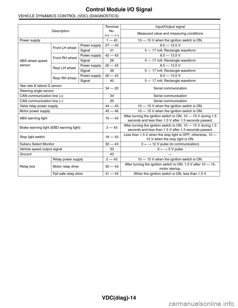
VDC(diag)-14
Control Module I/O Signal
VEHICLE DYNAMICS CONTROL (VDC) (DIAGNOSTICS)
Description
Te r m i n a l
No.
(+) — (–)
Input/Output signal
Measured value and measuring conditions
Pow er s up p ly 1 — 43 10 — 15 V w h e n t h e i gn i t io n sw it ch i s ON .
ABS wheel speed
sensor
Front LH wheelPowe r s u pp ly 27 — 4 3 8 . 5 — 1 3. 5 V
Signal 41 5 — 17 mA: Rectangle waveform
Front RH wheelPower supply 42 — 43 8.5 — 13.5 V
Signal 28 5 — 17 mA: Rectangle waveform
Rear LH wheelPower supply 25 — 43 8.5 — 13.5 V
Signal 39 5 — 17 mA: Rectangle waveform
Rear RH wheelPower supply 26 — 43 8.5 — 13.5 V
Signal 40 5 — 17 mA: Rectangle waveform
Ya w r a t e & l a t e r a l G s e n s o r34 — 20 Serial communicationSteering angle sensor
CAN communication line (+) 34 Serial communication
CAN communication line (–) 20 Serial communication
Valve relay power supply 44 — 43 10 — 15 V when the ignition switch is ON.
Motor power supply 45 — 46 10 — 15 V when the ignition switch is ON.
ABS warning light 16 — 43After turning the ignition switch to ON, 10 — 15 V during 1.5
seconds and less than 1.5 V after 1.5 seconds passed.
Brake warning light (EBD warning light) 3 — 43After turning the ignition switch to ON, 10 — 15 V during 1.5
seconds and less than 1.5 V after 1.5 seconds passed.
Stop light switch 18 — 43Less than 1.5 V when the stop light is OFF; otherwise, 10 —
15 V when the stop light is ON.
Subaru Select Monitor 32 — 43 0 ←→ 12 V pulse (in communication)
Ve h i c l e s p e e d o u t p u t s i g n a l 3 3 0 ←→ 5 V pulse
Ground 43 —
Relay box
Relay power supply 2 — 43 10 — 15 V when the ignition switch is ON.
Motor relay drive 30 — 43After turning the ignition switch to ON, 1.5 V after 10 — 15,
motor startup.
Fa i l s afe r e lay d r ive 31 — 4 3 W he n t h e i g ni t io n swit c h i s ON, l es s t ha n 1 . 5 V.
Page 1009 of 2453
![SUBARU TRIBECA 2009 1.G Service Workshop Manual VDC(diag)-17
Subaru Select Monitor
VEHICLE DYNAMICS CONTROL (VDC) (DIAGNOSTICS)
2. READ CURRENT DATA
1) On the «Main Menu» display screen, select the {Each System Check} and press the [YES] key.
2) SUBARU TRIBECA 2009 1.G Service Workshop Manual VDC(diag)-17
Subaru Select Monitor
VEHICLE DYNAMICS CONTROL (VDC) (DIAGNOSTICS)
2. READ CURRENT DATA
1) On the «Main Menu» display screen, select the {Each System Check} and press the [YES] key.
2)](/manual-img/17/7322/w960_7322-1008.png)
VDC(diag)-17
Subaru Select Monitor
VEHICLE DYNAMICS CONTROL (VDC) (DIAGNOSTICS)
2. READ CURRENT DATA
1) On the «Main Menu» display screen, select the {Each System Check} and press the [YES] key.
2) On the «System Selection Menu» display screen, select the {Brake Control} and press the [YES] key.
3) Press the [YES] key after {VDC AWD AT} is displayed.
4) On the «Brake Control Diagnosis» display screen, select the {Current Data Display/Save}, and then press
the [YES] key.
5) On the «Display Menu» screen, select the data display method and press the [YES] key.
6) Using a scroll key, scroll the display screen up or down until necessary data is shown.
•A list of the support data is shown in the following table.
NOTE:
For details concerning operation procedure, refer to the “SUBARU SELECT MONITOR OPERATION MAN-
UAL”.
Display Contents to be monitored Unit of measure
FR Wheel SpeedWheel speed detected by front ABS wheel speed sensor RH is dis-
played.km/h or MPH
FL Wheel SpeedWheel speed detected by front ABS wheel speed sensor LH is dis-
played.km/h or MPH
RR Wheel SpeedWheel speed detected by rear ABS wheel speed sensor RH is dis-
played.km/h or MPH
RL Wheel SpeedWheel speed detected by rear ABS wheel speed sensor LH is dis-
played.km/h or MPH
Fr o nt / Re ar G S e ns o r Ve h ic le f r on t / re a r ac ce le ra t io n d e te c te d by G se n so r is d i sp layed .m/s2
Lateral G Sensor Vehicle lateral acceleration detected by G sensor is displayed.m/s2
IG power supply voltage Voltage supplied to VDCCM&H/U is displayed. V
Steering Angle Sensor Steering angle detected by steering angle sensor is displayed. deg
Ya w R a t e S e n s o r V e h i c l e a n g u l a r s p e e d d e t e c t e d b y y a w r a t e s e n s o r i s d i s p l a y e d . d e g / s
Pressure Sensor Brake fluid pressure detected by pressure sensor is displayed. bar
ABS Control Flag ABS control condition is displayed. ON or OFF
EBD Control Flag EBD control condition is displayed. ON or OFF
Brake Switch Brake ON/OFF is displayed. ON or OFF
ABS Warning Light ON operation of the ABS warning light is displayed. ON or OFF
EBD Warning Light ON operation of the EBD warning light is displayed. ON or OFF
Motor Relay Signal Motor relay operation signal is displayed. ON or OFF
Motor Relay Monitor Motor relay monitor signal is displayed. ON or OFF
TCS Control Flag TCS control condition is displayed. ON or OFF
Va l ve R e l ay S i g n a l Va l v e r e l ay o p e r a t i o n s i g n a l i s d i s p l ay e d . O N o r O F F
VDC Control Flag VDC control condition is displayed. ON or OFF
VDC Warning Light ON operation of the VDC warning light is displayed. ON or OFF
OFF Light ON/OFF condition of TCS OFF indicator light is displayed. ON or OFF
E/G Control Prohibited Flag Engine control command signal is displayed. 1 or 0
OFF Switch Signal Operation condition of TCS OFF switch is displayed. ON or OFF
Motor Fail Safe Relay Drive
SignalMotor fail safe relay drive signal is displayed. ON or OFF
Page 1010 of 2453
![SUBARU TRIBECA 2009 1.G Service Workshop Manual VDC(diag)-18
Subaru Select Monitor
VEHICLE DYNAMICS CONTROL (VDC) (DIAGNOSTICS)
3. CLEAR MEMORY MODE
1) On the «Main Menu», select the {2. Each Sys-
tem Check} and press the [YES] key.
2) On SUBARU TRIBECA 2009 1.G Service Workshop Manual VDC(diag)-18
Subaru Select Monitor
VEHICLE DYNAMICS CONTROL (VDC) (DIAGNOSTICS)
3. CLEAR MEMORY MODE
1) On the «Main Menu», select the {2. Each Sys-
tem Check} and press the [YES] key.
2) On](/manual-img/17/7322/w960_7322-1009.png)
VDC(diag)-18
Subaru Select Monitor
VEHICLE DYNAMICS CONTROL (VDC) (DIAGNOSTICS)
3. CLEAR MEMORY MODE
1) On the «Main Menu», select the {2. Each Sys-
tem Check} and press the [YES] key.
2) On the «System Selection Menu» display
screen, select the {Brake Control} and press the
[YES] key.
3) Press the [YES] key after {VDC AWD AT} is dis-
played.
4) On the «Brake Control Diagnosis» display
screen, select the {Memory Clear} and press the
[YES] key.
5) When “Done” and “Turn ignition switch OFF” are
shown on the display screen, turn the Subaru Se-
lect Monitor and ignition switch to OFF.
NOTE:
For details concerning operation procedure, refer
to the “SUBARU SELECT MONITOR OPERATION
MANUAL”.
4. SEQUENCE CONTROL
5. FREEZE FRAME DATA
NOTE:
•Data stored at the time of trouble occurrence is
shown on display.
•Each time trouble occurs, the latest information
is stored in the freeze frame data in memory.
Display Contents to be monitored
Clear memory? DTC deleting function
Display Contents to be monitoredReference tar-
get
ABS
sequence
control
Operate the valve and
pump motor continuously
to perform the ABS
sequence control.
Sequence Con-
trol.>
VDC
sequence
control
Operate the valve and
pump motor continuously
to perform the VDC
sequence control.
Sequence Con-
trol.>
Display Contents to be monitored
IG CounterNumber of times ignition switch turned to
ON is displayed.
DTC The recorded failure code is displayed.
FR Wheel
Speed
Wheel speed detected by front ABS
wheel speed sensor RH is displayed in
km/h or MPH.
FL Wheel Speed
Wheel speed detected by front ABS
wheel speed sensor LH is displayed in
km/h or MPH.
RR Wheel
Speed
Wheel speed detected by rear ABS
wheel speed sensor RH is displayed in
km/h or MPH.
RL Wheel
Speed
Wheel speed detected by rear ABS
wheel speed sensor LH is displayed in
km/h or MPH.
Ve h i c l e S p e e dVe h i c l e s p e e d c a l c u l a t e d b y V D C c o n t r o l
module is displayed.
G Sensor First
ShaftThe sensor value for a 45° angle crossed
2 axis G sensor is displayed.G Sensor Sec-
ond Shaft
Ya w R a t e S e n -
sor
Ve h i c l e a n g u l a r s p e e d d e t e c t e d b y y a w
rate sensor is displayed.
IG power supply
voltage
Vo l t a g e s u p p l i e d t o V D C c o n t r o l m o d u l e
is displayed.
Steering Angle
Sensor
Steering angle detected by steering
angle sensor is displayed.
Pressure sen-
sor output
Brake fluid pressure detected by pres-
sure sensor is displayed.
Engine SpeedEngine speed on malfunction occur-
rence is displayed.
Acceleration
Opening AngleAcceleration opening is displayed.
Gear positionGear position on malfunction occurrence
is displayed.
Steering Angle
Sensor Malfunc-
tion Code
The recorded steering angle sensor fail-
ure code is displayed?
ABS Control
FlagABS control condition is displayed.
EBD Control
FlagEBD control condition is displayed.
Brake Switch Brake ON/OFF is displayed.
TCS Control
FlagTCS control condition is displayed.
VDC Control
FlagVDC control condition is displayed.
E/G Control Flag
Absolute angle
recognition flag
Whether the absolute angle was deter-
mined is displayed.
OFF Switch Sig-
nal
Operation condition of TCS OFF switch
is displayed.
Page 1036 of 2453
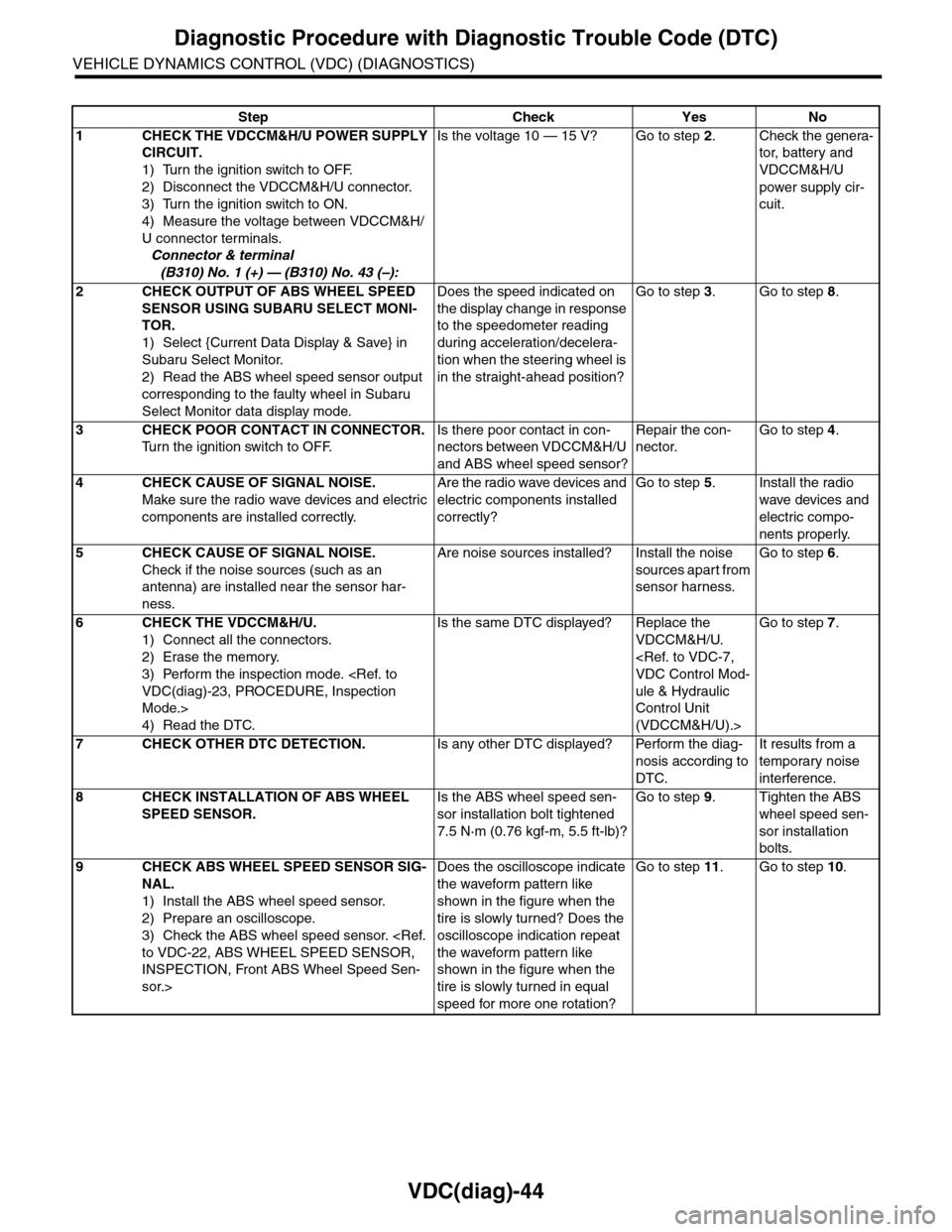
VDC(diag)-44
Diagnostic Procedure with Diagnostic Trouble Code (DTC)
VEHICLE DYNAMICS CONTROL (VDC) (DIAGNOSTICS)
Step Check Yes No
1CHECK THE VDCCM&H/U POWER SUPPLY
CIRCUIT.
1) Turn the ignition switch to OFF.
2) Disconnect the VDCCM&H/U connector.
3) Turn the ignition switch to ON.
4) Measure the voltage between VDCCM&H/
U connector terminals.
Connector & terminal
(B310) No. 1 (+) — (B310) No. 43 (–):
Is the voltage 10 — 15 V? Go to step 2.Check the genera-
tor, batter y and
VDCCM&H/U
power supply cir-
cuit.
2CHECK OUTPUT OF ABS WHEEL SPEED
SENSOR USING SUBARU SELECT MONI-
TOR.
1) Select {Current Data Display & Save} in
Subaru Select Monitor.
2) Read the ABS wheel speed sensor output
corresponding to the faulty wheel in Subaru
Select Monitor data display mode.
Does the speed indicated on
the display change in response
to the speedometer reading
during acceleration/decelera-
tion when the steering wheel is
in the straight-ahead position?
Go to step 3.Go to step 8.
3CHECK POOR CONTACT IN CONNECTOR.
Tu r n t h e i g n i t i o n s w i t c h t o O F F.
Is there poor contact in con-
nectors between VDCCM&H/U
and ABS wheel speed sensor?
Repair the con-
nector.
Go to step 4.
4CHECK CAUSE OF SIGNAL NOISE.
Make sure the radio wave devices and electric
components are installed correctly.
Are the radio wave devices and
electric components installed
correctly?
Go to step 5.Install the radio
wave devices and
electric compo-
nents properly.
5CHECK CAUSE OF SIGNAL NOISE.
Check if the noise sources (such as an
antenna) are installed near the sensor har-
ness.
Are noise sources installed? Install the noise
sources apart from
sensor harness.
Go to step 6.
6CHECK THE VDCCM&H/U.
1) Connect all the connectors.
2) Erase the memory.
3) Perform the inspection mode.
Mode.>
4) Read the DTC.
Is the same DTC displayed? Replace the
VDCCM&H/U.
ule & Hydraulic
Control Unit
(VDCCM&H/U).>
Go to step 7.
7CHECK OTHER DTC DETECTION.Is any other DTC displayed? Perform the diag-
nosis according to
DTC.
It results from a
temporary noise
interference.
8CHECK INSTALLATION OF ABS WHEEL
SPEED SENSOR.
Is the ABS wheel speed sen-
sor installation bolt tightened
7.5 N·m (0.76 kgf-m, 5.5 ft-lb)?
Go to step 9.Tighten the ABS
wheel speed sen-
sor installation
bolts.
9CHECK ABS WHEEL SPEED SENSOR SIG-
NAL.
1) Install the ABS wheel speed sensor.
2) Prepare an oscilloscope.
3) Check the ABS wheel speed sensor.
INSPECTION, Front ABS Wheel Speed Sen-
sor.>
Does the oscilloscope indicate
the waveform pattern like
shown in the figure when the
tire is slowly turned? Does the
oscilloscope indication repeat
the waveform pattern like
shown in the figure when the
tire is slowly turned in equal
speed for more one rotation?
Go to step 11.Go to step 10.
Page 1066 of 2453
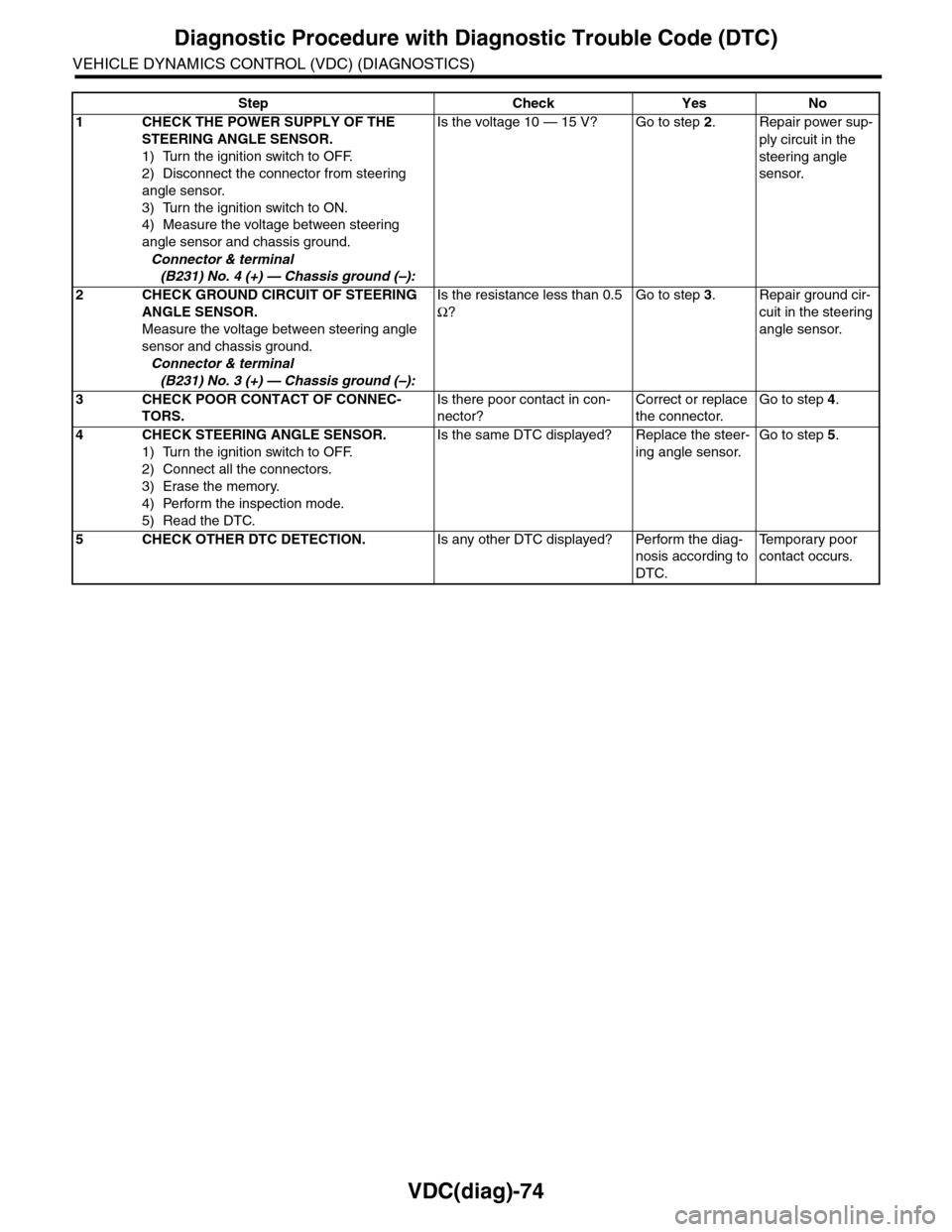
VDC(diag)-74
Diagnostic Procedure with Diagnostic Trouble Code (DTC)
VEHICLE DYNAMICS CONTROL (VDC) (DIAGNOSTICS)
Step Check Yes No
1CHECK THE POWER SUPPLY OF THE
STEERING ANGLE SENSOR.
1) Turn the ignition switch to OFF.
2) Disconnect the connector from steering
angle sensor.
3) Turn the ignition switch to ON.
4) Measure the voltage between steering
angle sensor and chassis ground.
Connector & terminal
(B231) No. 4 (+) — Chassis ground (–):
Is the voltage 10 — 15 V? Go to step 2.Repair power sup-
ply circuit in the
steering angle
sensor.
2CHECK GROUND CIRCUIT OF STEERING
ANGLE SENSOR.
Measure the voltage between steering angle
sensor and chassis ground.
Connector & terminal
(B231) No. 3 (+) — Chassis ground (–):
Is the resistance less than 0.5
Ω?
Go to step 3.Repair ground cir-
cuit in the steering
angle sensor.
3CHECK POOR CONTACT OF CONNEC-
TORS.
Is there poor contact in con-
nector?
Correct or replace
the connector.
Go to step 4.
4CHECK STEERING ANGLE SENSOR.
1) Turn the ignition switch to OFF.
2) Connect all the connectors.
3) Erase the memory.
4) Perform the inspection mode.
5) Read the DTC.
Is the same DTC displayed? Replace the steer-
ing angle sensor.
Go to step 5.
5CHECK OTHER DTC DETECTION.Is any other DTC displayed? Perform the diag-
nosis according to
DTC.
Te m p o r a r y p o o r
contact occurs.
Page 1068 of 2453
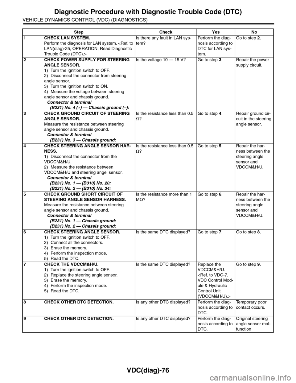
VDC(diag)-76
Diagnostic Procedure with Diagnostic Trouble Code (DTC)
VEHICLE DYNAMICS CONTROL (VDC) (DIAGNOSTICS)
Step Check Yes No
1CHECK LAN SYSTEM.
Perfor m the diagnosis for LAN system.
Tr o u b l e C o d e ( D T C ) . >
Is there any fault in LAN sys-
tem?
Pe r for m t h e d ia g -
nosis according to
DTC for LAN sys-
tem.
Go to step 2.
2CHECK POWER SUPPLY FOR STEERING
ANGLE SENSOR.
1) Turn the ignition switch to OFF.
2) Disconnect the connector from steering
angle sensor.
3) Turn the ignition switch to ON.
4) Measure the voltage between steering
angle sensor and chassis ground.
Connector & terminal
(B231) No. 4 (+) — Chassis ground (–):
Is the voltage 10 — 15 V? Go to step 3.Repair the power
supply circuit.
3CHECK GROUND CIRCUIT OF STEERING
ANGLE SENSOR.
Measure the resistance between steering
angle sensor and chassis ground.
Connector & terminal
(B231) No. 3 — Chassis ground:
Is the resistance less than 0.5
Ω?
Go to step 4.Repair ground cir-
cuit in the steering
angle sensor.
4CHECK STEERING ANGLE SENSOR HAR-
NESS.
1) Disconnect the connector from the
VDCCM&H/U.
2) Measure the resistance between
VDCCM&H/U and steering angel sensor.
Connector & terminal
(B231) No. 1 — (B310) No. 20:
(B231) No. 2 — (B310) No. 34:
Is the resistance less than 0.5
Ω?
Go to step 5.Repair the har-
ness between the
steering angle
sensor and
VDCCM&H/U.
5CHECK GROUND SHORT CIRCUIT OF
STEERING ANGLE SENSOR HARNESS.
Measure the resistance between steering
angle sensor and chassis ground.
Connector & terminal
(B231) No. 1 — Chassis ground:
(B231) No. 2 — Chassis ground:
Is the resistance more than 1
MΩ?
Go to step 6.Repair the har-
ness between the
steering angle
sensor and
VDCCM&H/U.
6CHECK STEERING ANGLE SENSOR.
1) Turn the ignition switch to OFF.
2) Connect all the connectors.
3) Erase the memory.
4) Perform the inspection mode.
5) Read the DTC.
Is the same DTC displayed? Go to step 7.Go to step 8.
7CHECK THE VDCCM&H/U.
1) Turn the ignition switch to OFF.
2) Replace the steering angle sensor.
3) Erase the memory.
4) Perform the inspection mode.
5) Read the DTC.
Is the same DTC displayed? Replace the
VDCCM&H/U.
ule & Hydraulic
Control Unit
(VDCCM&H/U).>
Go to step 9.
8CHECK OTHER DTC DETECTION.Is any other DTC displayed? Perform the diag-
nosis according to
DTC.
Te m p o r a r y p o o r
contact occurs.
9CHECK OTHER DTC DETECTION.Is any other DTC displayed? Perform the diag-
nosis according to
DTC.
Original steering
angle sensor mal-
function
Page 1081 of 2453
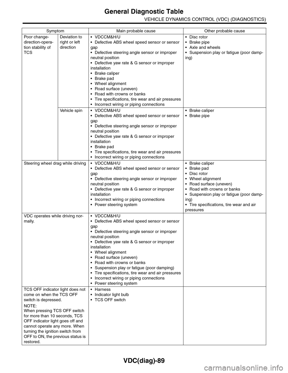
VDC(diag)-89
General Diagnostic Table
VEHICLE DYNAMICS CONTROL (VDC) (DIAGNOSTICS)
Po or ch a ng e -
direction-opera-
tion stability of
TCS
Deviation to
right or left
direction
•VDCCM&H/U
•Defective ABS wheel speed sensor or sensor
gap
•Defective steering angle sensor or improper
neutral position
•Defective yaw rate & G sensor or improper
installation
•Brake caliper
•Brake pad
•Wheel alignment
•Road surface (uneven)
•Road with crowns or banks
•Tire specifications, tire wear and air pressures
•Incorrect wiring or piping connections
•Disc rotor
•Brake pipe
•Axle and wheels
•Suspension play or fatigue (poor damp-
ing)
Ve h i c l e s p i n • V D C C M & H / U
•Defective ABS wheel speed sensor or sensor
gap
•Defective steering angle sensor or improper
neutral position
•Defective yaw rate & G sensor or improper
installation
•Brake pad
•Tire specifications, tire wear and air pressures
•Incorrect wiring or piping connections
•Brake caliper
•Brake pipe
Steering wheel drag while driving • VDCCM&H/U
•Defective ABS wheel speed sensor or sensor
gap
•Defective steering angle sensor or improper
neutral position
•Defective yaw rate & G sensor or improper
installation
•Incorrect wiring or piping connections
•Power steering system
•Brake caliper
•Brake pad
•Disc rotor
•Wheel alignment
•Road surface (uneven)
•Road with crowns or banks
•Suspension play or fatigue (poor damp-
ing)
•Tire specifications, tire wear and air
pressures
VDC operates while driving nor-
mally.
•VDCCM&H/U
•Defective ABS wheel speed sensor or sensor
gap
•Defective steering angle sensor or improper
neutral position
•Defective yaw rate & G sensor or improper
installation
•Wheel alignment
•Road surface (uneven)
•Road with crowns or banks
•Suspension play or fatigue (poor damping)
•Tire specifications, tire wear and air pressures
•Incorrect wiring or piping connections
•Power steering system
TCS OFF indicator light does not
come on when the TCS OFF
switch is depressed.
NOTE:When pressing TCS OFF switch
for more than 10 seconds, TCS
OFF indicator light goes off and
cannot operate any more. When
turning the ignition switch from
OFF to ON, the previous status is
restored.
•Harness
•Indicator light bulb
•TCS OFF switch
Symptom Main probable cause Other probable cause
Page 1166 of 2453
EN(H6DO)(diag)-5
General Description
ENGINE (DIAGNOSTICS)
3. General Description
A: CAUTION
1) Airbag system wiring harness is routed near the
ECM, main relay and fuel pump relay.
CAUTION:
•All airbag system wiring harnesses and con-
nectors are colored yellow. Do not use electri-
cal test equipment on these circuits.
•Be careful not to damage the airbag system
wiring harness when servicing the ECM, TCM,
main relay and fuel pump relay.
2) Never connect the battery in reverse polarity.
•The ECM will be destroyed instantly.
•The fuel injector and other parts will be dam-
aged.
3) Do not disconnect the battery terminals while the
engine is running.
A large counter electromotive force will be generat-
ed in the generator, and this voltage may damage
electronic parts such as ECM etc.
4) Before disconnecting the connectors of each
sensor and ECM, be sure to turn the ignition switch
to OFF. Perform the clear memory mode after con-
necting the connectors.
5) Poor contact has been identified as a primary
cause of this problem. Measure the voltage or re-
sistance of individual sensor or all electrical control
modules using a tapered pin with a diameter of less
than 0.64 mm (0.025 in). Do not insert the pin more
than 5 mm (0.20 in) into the part.
6) Remove the ECM from the located position after
disconnecting two cables on battery.
Otherwise, the ECM may be damaged.
CAUTION:
When replacing the ECM, be careful not to use
the wrong spec. ECM to avoid any damage on
the fuel injection system.
7) Connectors of each sensor in the engine com-
partment and the harness connectors on the en-
gine side and body side are all designed to be
waterproof. Even if the connectors are waterproof,
take care not to allow water to get into them when
washing the vehicle, or when servicing the vehicle
in rainy weather.
8) Use ECM mounting stud bolts as the grounding
point to chassis when measuring voltage and resis-
tance in the passenger compartment.
9) Use the engine ground terminal or engine as-
sembly as the grounding point to chassis when
measuring the voltage and resistance in engine
compartment.
10) Every MFI-related part is a precision part. Do
not drop them.
11) Observe the following cautions when installing
a radio in MFI equipped models.
CAUTION:
•The antenna must be kept as far apart as pos-
sible from control unit. (The ECM is located un-
der the steering column, inside of the
instrument panel lower trim panel.)
•The antenna feeder must be placed as far apart
as possible from the ECM and MFI harness.
•Carefully adjust the antenna for correct
matching.
•When mounting a large power type radio, pay
special attention to the three items mentioned
above.
•Incorrect installation of the radio may affect
the operation of ECM.
12) Release the pressure in the fuel system before
disconnecting the fuel hose. If engine starts during
this operation, run it until it stops.
13) For the model with ABS, the ABS warning light
may illuminate when performing driving test with
jacked-up or lifted-up condition, but this is not a
system malfunction. The reason for this is the
speed difference between the front and rear
wheels. After diagnosis of engine control system,
perform the ABS memory clear procedure of self-
diagnosis function.
B: INSPECTION
Before performing diagnostics, check the following
item which might affect engine problems.
1. BATTERY
1) Measure the battery voltage and specific gravity
of electrolyte.
Standard voltage: 12 V
Specific gravity: Above 1.260
2) Check the condition of the main and other fuses,
and harnesses and connectors. Also check for
proper grounding.
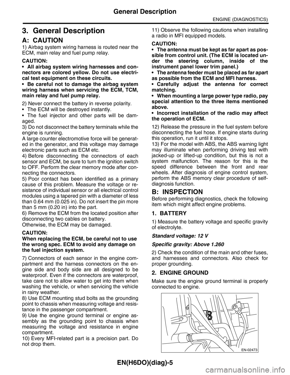
2. ENGINE GROUND
Make sure the engine ground terminal is properly
connected to engine.
EN-02473