2009 SUBARU TRIBECA coolant temperature sensor
[x] Cancel search: coolant temperature sensorPage 1706 of 2453
GD(H6DO)-94
Diagnostic Trouble Code (DTC) Detecting Criteria
GENERAL DESCRIPTION
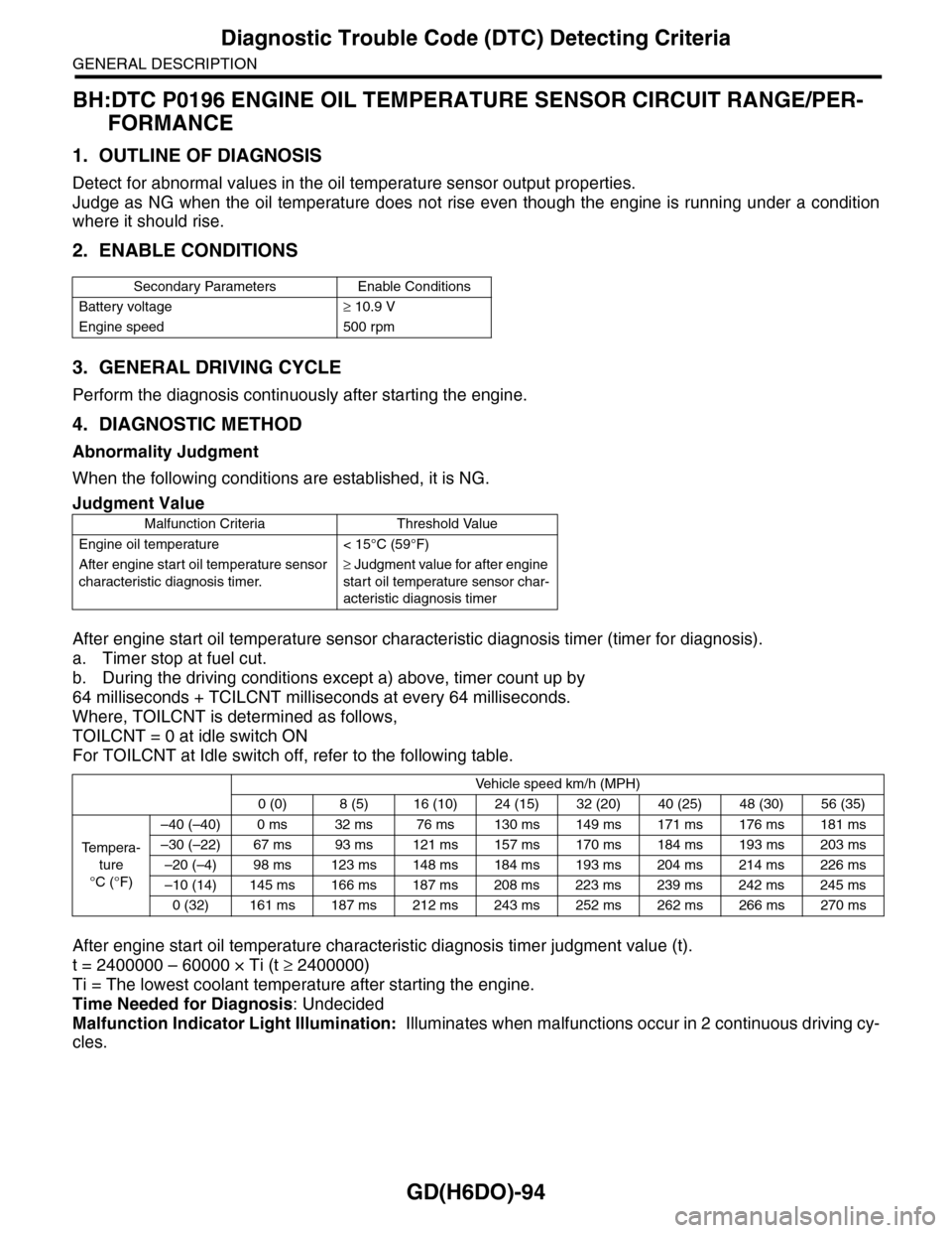
BH:DTC P0196 ENGINE OIL TEMPERATURE SENSOR CIRCUIT RANGE/PER-
FORMANCE
1. OUTLINE OF DIAGNOSIS
Detect for abnormal values in the oil temperature sensor output properties.
Judge as NG when the oil temperature does not rise even though the engine is running under a condition
where it should rise.
2. ENABLE CONDITIONS
3. GENERAL DRIVING CYCLE
Perform the diagnosis continuously after starting the engine.
4. DIAGNOSTIC METHOD
Abnormality Judgment
When the following conditions are established, it is NG.
After engine start oil temperature sensor characteristic diagnosis timer (timer for diagnosis).
a. Timer stop at fuel cut.
b. During the driving conditions except a) above, timer count up by
64 milliseconds + TCILCNT milliseconds at every 64 milliseconds.
Where, TOILCNT is determined as follows,
TOILCNT = 0 at idle switch ON
For TOILCNT at Idle switch off, refer to the following table.
After engine start oil temperature characteristic diagnosis timer judgment value (t).
t = 2400000 – 60000 × Ti (t ≥ 2400000)
Ti = The lowest coolant temperature after starting the engine.
Time Needed for Diagnosis: Undecided
Malfunction Indicator Light Illumination: Illuminates when malfunctions occur in 2 continuous driving cy-
cles.
Secondary Parameters Enable Conditions
Battery voltage≥ 10.9 V
Engine speed 500 rpm
Judgment Value
Malfunction Criteria Threshold Value
Engine oil temperature < 15°C (59°F)
After engine start oil temperature sensor
characteristic diagnosis timer.
≥ Judgment value for after engine
start oil temperature sensor char-
acteristic diagnosis timer
Vehicle speed km/h (MPH)
0 (0) 8 (5) 16 (10) 24 (15) 32 (20) 40 (25) 48 (30) 56 (35)
Te m p e r a -
ture
°C (°F)
–40 (–40) 0 ms 32 ms 76 ms 130 ms 149 ms 171 ms 176 ms 181 ms
–30 (–22) 67 ms 93 ms 121 ms 157 ms 170 ms 184 ms 193 ms 203 ms
–20 (–4) 98 ms 123 ms 148 ms 184 ms 193 ms 204 ms 214 ms 226 ms
–10 (14) 145 ms 166 ms 187 ms 208 ms 223 ms 239 ms 242 ms 245 ms
0 (32) 161 ms 187 ms 212 ms 243 ms 252 ms 262 ms 266 ms 270 ms
Page 1734 of 2453
GD(H6DO)-122
Diagnostic Trouble Code (DTC) Detecting Criteria
GENERAL DESCRIPTION
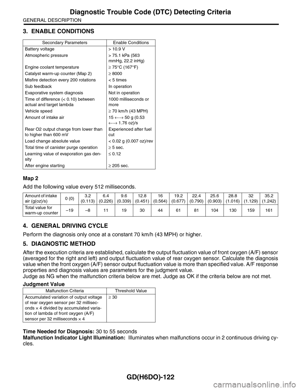
3. ENABLE CONDITIONS
Map 2
Add the following value every 512 milliseconds.
4. GENERAL DRIVING CYCLE
Perform the diagnosis only once at a constant 70 km/h (43 MPH) or higher.
5. DIAGNOSTIC METHOD
After the execution criteria are established, calculate the output fluctuation value of front oxygen (A/F) sensor
(averaged for the right and left) and output fluctuation value of rear oxygen sensor. Calculate the diagnosis
value when the front oxygen (A/F) sensor output fluctuation value is more than specified value. A/F response
properties and diagnosis values are parameters for the judgment value.
Judge as NG when the malfunction criteria below are met. Judge as OK if the criteria below are not met.
Time Needed for Diagnosis: 30 to 55 seconds
Malfunction Indicator Light Illumination: Illuminates when malfunctions occur in 2 continuous driving cy-
cles.
Secondary Parameters Enable Conditions
Battery voltage > 10.9 V
Atmospheric pressure > 75.1 kPa (563
mmHg, 22.2 inHg)
Engine coolant temperature≥ 75°C (167°F)
Catalyst warm-up counter (Map 2)≥ 8000
Misfire detection every 200 rotations < 5 times
Sub feedback In operation
Evaporative system diagnosis Not in operation
Time of difference (< 0.10) between
actual and target lambda
1000 milliseconds or
more
Ve h i c l e s p e e d≥ 70 km/h (43 MPH)
Amount of intake air 15 ←→ 50 g (0.53
←→ 1.76 oz)/s
Rear O2 output change from lower than
to higher than 600 mV
Experienced after fuel
cut
Load change absolute value < 0.02 g (0.007 oz)/rev
To t a l t i m e o f c a n i s t e r p u r g e o p e r a t i o n≥ 5 sec.
Learning value of evaporation gas den-
sity
≤ 0.12
After engine starting≥ 205 sec.
Amount of intake
air (g(oz)/s)0 (0)3.2
(0.113)
6.4
(0.226)
9.6
(0.339)
12.8
(0.451)
16
(0.564)
19.2
(0.677)
22.4
(0.790)
25.6
(0.903)
28.8
(1.016)
32
(1.129)
35.2
(1.242)
To t a l v a l u e f o r
warm-up counter–19 –8 11 19 30 44 61 81 104 130 159 161
Judgment Value
Malfunction Criteria Threshold Value
Accumulated variation of output voltage
of rear oxygen sensor per 32 millisec-
onds × 4 divided by accumulated varia-
tion of lambda of front oxygen (A/F)
sensor per 32 milliseconds × 4
≥ 30
Page 1794 of 2453
GD(H6DO)-182
Diagnostic Trouble Code (DTC) Detecting Criteria
GENERAL DESCRIPTION
DF:DTC P1152 O2 SENSOR CIRCUIT RANGE/PERFORMANCE (LOW) (BANK 1
SENSOR 1)
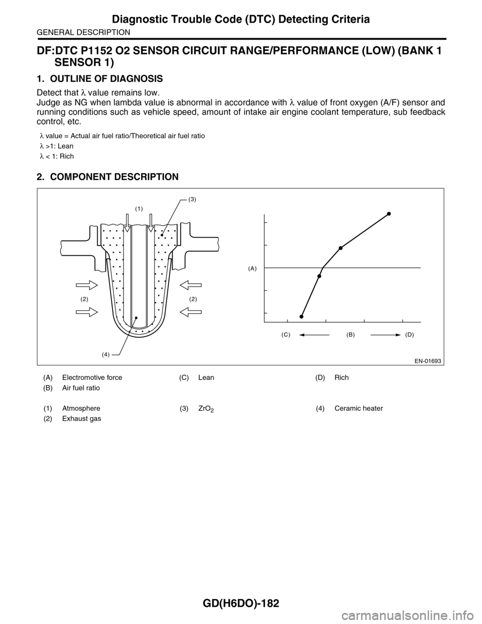
1. OUTLINE OF DIAGNOSIS
Detect that λ value remains low.
Judge as NG when lambda value is abnormal in accordance with λ value of front oxygen (A/F) sensor and
running conditions such as vehicle speed, amount of intake air engine coolant temperature, sub feedback
control, etc.
2. COMPONENT DESCRIPTION
λ value = Actual air fuel ratio/Theoretical air fuel ratio
λ >1: Lean
λ < 1: Rich
(A) Electromotive force (C) Lean (D) Rich
(B) Air fuel ratio
(1) Atmosphere (3) ZrO2(4) Ceramic heater
(2) Exhaust gas
(1)
(2)
(4)
(2)
(3)
EN-01693
(C) (B) (D)
(A)
Page 1795 of 2453
GD(H6DO)-183
Diagnostic Trouble Code (DTC) Detecting Criteria
GENERAL DESCRIPTION
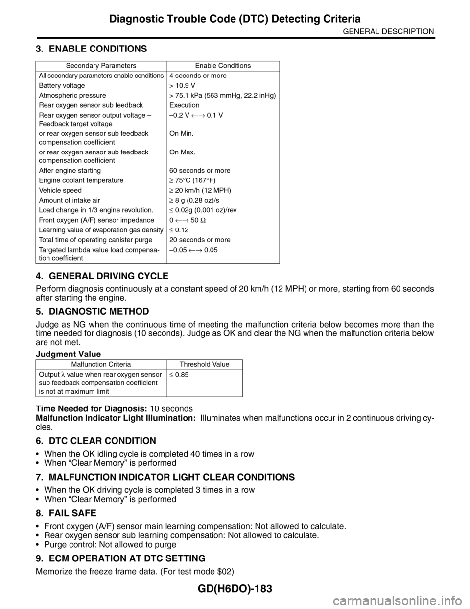
3. ENABLE CONDITIONS
4. GENERAL DRIVING CYCLE
Perform diagnosis continuously at a constant speed of 20 km/h (12 MPH) or more, starting from 60 seconds
after starting the engine.
5. DIAGNOSTIC METHOD
Judge as NG when the continuous time of meeting the malfunction criteria below becomes more than the
time needed for diagnosis (10 seconds). Judge as OK and clear the NG when the malfunction criteria below
are not met.
Time Needed for Diagnosis: 10 seconds
Malfunction Indicator Light Illumination: Illuminates when malfunctions occur in 2 continuous driving cy-
cles.
6. DTC CLEAR CONDITION
•When the OK idling cycle is completed 40 times in a row
•When “Clear Memory” is performed
7. MALFUNCTION INDICATOR LIGHT CLEAR CONDITIONS
•When the OK driving cycle is completed 3 times in a row
•When “Clear Memory” is performed
8. FAIL SAFE
•Front oxygen (A/F) sensor main learning compensation: Not allowed to calculate.
•Rear oxygen sensor sub learning compensation: Not allowed to calculate.
•Purge control: Not allowed to purge
9. ECM OPERATION AT DTC SETTING
Memorize the freeze frame data. (For test mode $02)
Secondary Parameters Enable Conditions
All secondary parameters enable conditions4 seconds or more
Battery voltage > 10.9 V
Atmospheric pressure > 75.1 kPa (563 mmHg, 22.2 inHg)
Rear oxygen sensor sub feedback Execution
Rear oxygen sensor output voltage –
Feedback target voltage
–0.2 V ←→ 0.1 V
or rear oxygen sensor sub feedback
compensation coefficient
On Min.
or rear oxygen sensor sub feedback
compensation coefficient
On Max.
After engine starting 60 seconds or more
Engine coolant temperature≥ 75°C (167°F)
Ve h i c l e s p e e d≥ 20 km/h (12 MPH)
Amount of intake air≥ 8 g (0.28 oz)/s
Load change in 1/3 engine revolution.≤ 0.02g (0.001 oz)/rev
Fr o nt ox yg e n ( A / F) s en so r im pe d an c e 0 ←→ 50 Ω
Learning value of evaporation gas density≤ 0.12
To t a l t i m e o f o p e r a t i n g c a n i s t e r p u r g e 2 0 s e c o n d s o r m o r e
Ta r g e t e d l a m b d a v a l u e l o a d c o m p e n s a -
tion coefficient
–0.05 ←→ 0.05
Judgment Value
Malfunction Criteria Threshold Value
Output λ value when rear oxygen sensor
sub feedback compensation coefficient
is not at maximum limit
≤ 0.85
Page 1796 of 2453
GD(H6DO)-184
Diagnostic Trouble Code (DTC) Detecting Criteria
GENERAL DESCRIPTION
DG:DTC P1153 O2 SENSOR CIRCUIT RANGE/PERFORMANCE (HIGH) (BANK 1
SENSOR 1)
1. OUTLINE OF DIAGNOSIS
Detect that λ value remains high.
Judge as NG when lambda value is abnormal in accordance with λ value of front oxygen (A/F) sensor and
running conditions such as vehicle speed, amount of intake air engine coolant temperature, sub feedback
control, etc.
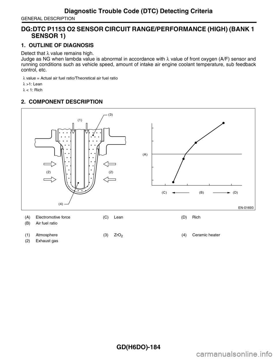
2. COMPONENT DESCRIPTION
λ value = Actual air fuel ratio/Theoretical air fuel ratio
λ >1: Lean
λ < 1: Rich
(A) Electromotive force (C) Lean (D) Rich
(B) Air fuel ratio
(1) Atmosphere (3) ZrO2(4) Ceramic heater
(2) Exhaust gas
(1)
(2)
(4)
(2)
(3)
EN-01693
(C) (B) (D)
(A)
Page 1797 of 2453
GD(H6DO)-185
Diagnostic Trouble Code (DTC) Detecting Criteria
GENERAL DESCRIPTION
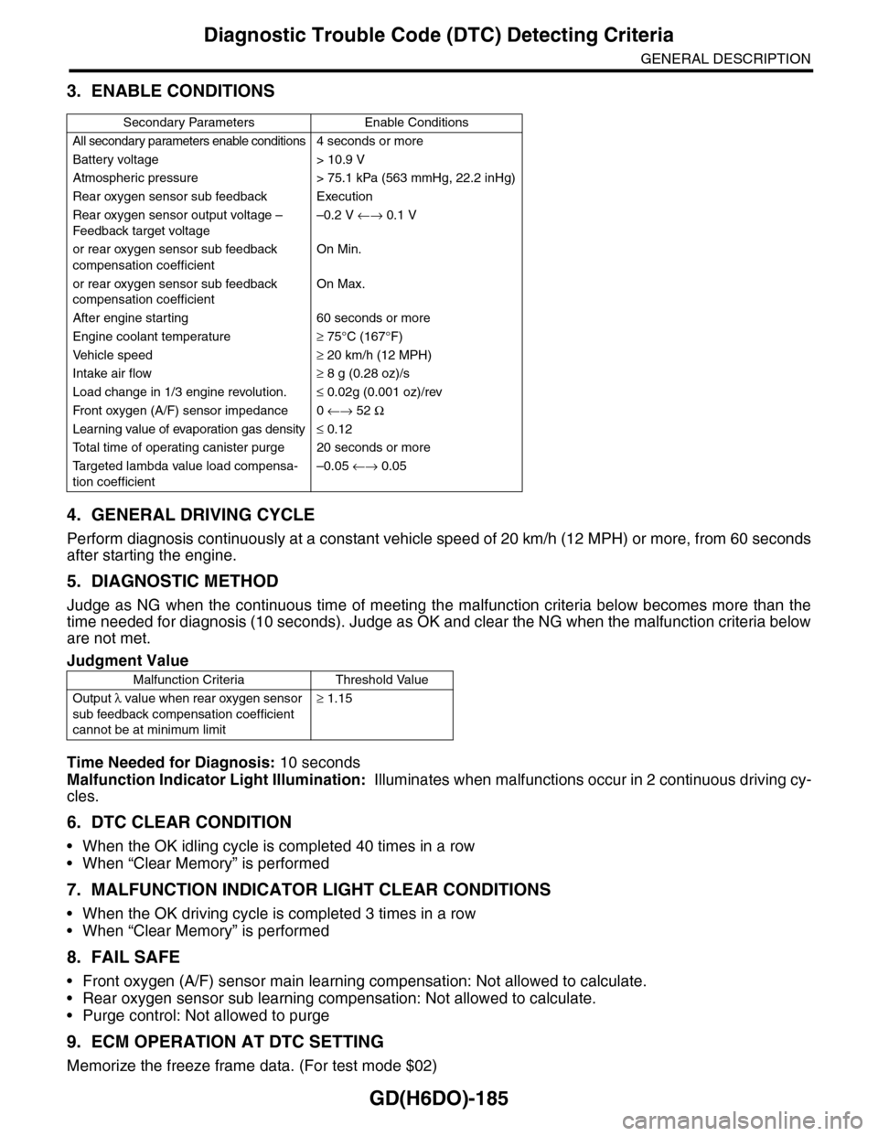
3. ENABLE CONDITIONS
4. GENERAL DRIVING CYCLE
Perform diagnosis continuously at a constant vehicle speed of 20 km/h (12 MPH) or more, from 60 seconds
after starting the engine.
5. DIAGNOSTIC METHOD
Judge as NG when the continuous time of meeting the malfunction criteria below becomes more than the
time needed for diagnosis (10 seconds). Judge as OK and clear the NG when the malfunction criteria below
are not met.
Time Needed for Diagnosis: 10 seconds
Malfunction Indicator Light Illumination: Illuminates when malfunctions occur in 2 continuous driving cy-
cles.
6. DTC CLEAR CONDITION
•When the OK idling cycle is completed 40 times in a row
•When “Clear Memory” is performed
7. MALFUNCTION INDICATOR LIGHT CLEAR CONDITIONS
•When the OK driving cycle is completed 3 times in a row
•When “Clear Memory” is performed
8. FAIL SAFE
•Front oxygen (A/F) sensor main learning compensation: Not allowed to calculate.
•Rear oxygen sensor sub learning compensation: Not allowed to calculate.
•Purge control: Not allowed to purge
9. ECM OPERATION AT DTC SETTING
Memorize the freeze frame data. (For test mode $02)
Secondary Parameters Enable Conditions
All secondary parameters enable conditions4 seconds or more
Battery voltage > 10.9 V
Atmospheric pressure > 75.1 kPa (563 mmHg, 22.2 inHg)
Rear oxygen sensor sub feedback Execution
Rear oxygen sensor output voltage –
Feedback target voltage
–0.2 V ←→ 0.1 V
or rear oxygen sensor sub feedback
compensation coefficient
On Min.
or rear oxygen sensor sub feedback
compensation coefficient
On Max.
After engine starting 60 seconds or more
Engine coolant temperature≥ 75°C (167°F)
Ve h i c l e s p e e d≥ 20 km/h (12 MPH)
Intake air flow≥ 8 g (0.28 oz)/s
Load change in 1/3 engine revolution.≤ 0.02g (0.001 oz)/rev
Fr o nt ox yg e n ( A / F) s en so r im pe d an c e 0 ←→ 52 Ω
Learning value of evaporation gas density≤ 0.12
To t a l t i m e o f o p e r a t i n g c a n i s t e r p u r g e 2 0 s e c o n d s o r m o r e
Ta r g e t e d l a m b d a v a l u e l o a d c o m p e n s a -
tion coefficient
–0.05 ←→ 0.05
Judgment Value
Malfunction Criteria Threshold Value
Output λ value when rear oxygen sensor
sub feedback compensation coefficient
cannot be at minimum limit
≥ 1.15
Page 1906 of 2453
ME(H6DO)-40
Preparation for Overhaul
MECHANICAL
12.Preparation for Overhaul
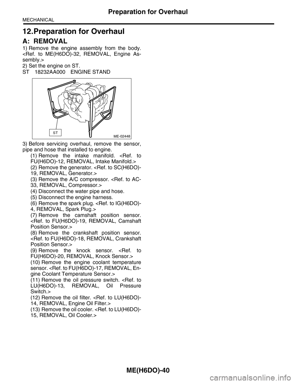
A: REMOVAL
1) Remove the engine assembly from the body.
2) Set the engine on ST.
ST 18232AA000 ENGINE STAND
3) Before servicing overhaul, remove the sensor,
pipe and hose that installed to engine.
(1) Remove the intake manifold.
(2) Remove the generator.
(3) Remove the A/C compressor.
(4) Disconnect the water pipe and hose.
(5) Disconnect the engine harness.
(6) Remove the spark plug.
(7) Remove the camshaft position sensor.
(8) Remove the crankshaft position sensor.
(9) Remove the knock sensor.
(10) Remove the engine coolant temperature
sensor.
(11) Remove the oil pressure switch.
Switch.>
(12) Remove the oil filter.
(13) Remove the oil cooler.
STME-02448
Page 2317 of 2453
WI-33
Engine Electrical System
WIRING SYSTEM
WI-08040
A3D2
D22D23
POWERCIRCUIT
COMBINATION METER
C16B27D18D19D20D21
C11C22
C6
B23B29B31B21
1
2
3
4
5
6
ACCELERATORPEDAL POSITIONSENSOR
JOINT CONNECTOR A
JOINT CONNECTOR
MALFUNCTION INDICATOR LIGHTOIL PRESSUREWARNING LIGHT
I/F
I/F
I/F
VDC CONTROL MODULE
IGNITION COIL NO.1
BODY INTEGRATED UNIT(CAN COMMUNICATION LINE)
OILPRESSURESWITCH
CRANKSHAFT POSITION SENSORA13A14
ENGINE GROUND
ECM
A18A28
D4D5
A19B22A6A29A34
D15B30
D14D17D16D31D30
ELECTRONIC THROTTLE CONTROL
A24
A25A16
A15
A32
D1
MANIFOLD ABSOLUTE PRESSURE SENSOR
ENGINE COOLANT TEMPRERATURE SENSOR
VVL DIAGNOSIS OIL PRESSURE SWITCH RH
D25D24
KNOCK SENSOR 2
D6D26D7
A5
MICRO COMPUTER
CAN TRANSCEIVER &RECEIVER
OIL SWITCHING SOLENOID VALVE RH
TA C H O -METER
SPEEDMETER
ENGINECOOLANTTEM-PERATUREGAUGE
DATA LINK CONNECTOR
TEST MODECONNECTOR
OIL TEMPERATURE SENSORA23
A31D3
VVL DIAGNOSIS OIL PRESSURE SWITCH LH
KNOCK SENSOR 1
OIL SWITCHING SOLENOID VALVE LH
INTAKE OIL FLOW CONTROL SOLENOID VALVE RH
INTAKE OIL FLOW CONTROL SOLENOID VALVE LH
IGNITION COIL NO.2 IGNITION COIL NO.3 IGNITION COIL NO.4 IGNITION COIL NO.5 IGNITION COIL NO.6
789