2009 RENAULT SCENIC lock
[x] Cancel search: lockPage 229 of 273
DIESEL INJECTION
Fault finding – Fault Finding Chart13B
13B -229V3 MR-372-J84-13B250$855.mif
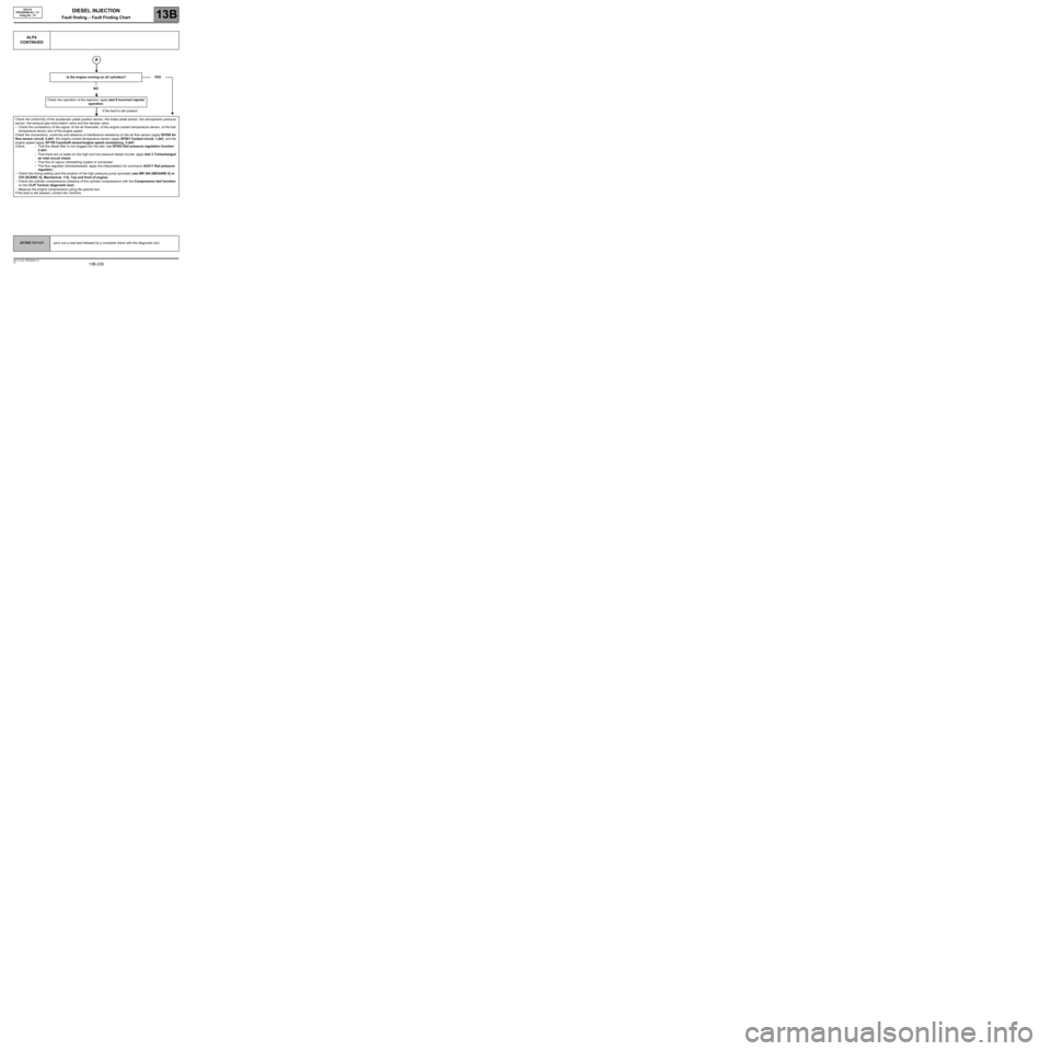
ALP4
CONTINUED
Is the engine running on all cylinders?
NO
Check the operation of the injectors: apply test 8 Incorrect injector
operation.
If the fault is still present
Check the conformity of the accelerator pedal position sensor, the brake pedal sensor, the atmospheric pressure
sensor, the exhaust gas recirculation valve and the damper valve.
–Check the consistency of the signal: of the air flowmeter, of the engine coolant temperature sensor, of the fuel
temperature sensor and of the engine speed.
Check the connections, continuity and absence of interference resistance on the air flow sensor (apply DF056 Air
flow sensor circuit, 2.def), the engine coolant temperature sensor (apply DF001 Coolant circuit, 1.def), and the
engine speed (apply DF195 Camshaft sensor/engine speed consistency, 2.def).
Check: – That the diesel filter is not clogged (for the test, see DF053 Rail pressure regulation function
2.def).
–That there are no leaks on the high and low pressure diesel circuits: apply test 3 Turbocharged
air inlet circuit check.
–That the oil vapour rebreathing system is connected.
–The flow regulator (blocked/seized, apply the interpretation for command: AC011 Rail pressure
regulator).
–Check the timing setting (and the position of the high pressure pump sprocket) (see MR 364 (MEGANE II) or
370 (SCENIC II), Mechanical, 11A, Top and front of engine).
–Check the cylinder compressions (balance of the cylinder compressions with the Compression test function
on the CLIP Technic diagnostic tool).
–Measure the engine compressions using the special tool.
If the fault is still present, contact the Techline.YES
EDC16
PROGRAM No.: C1
Vdiag No.: 51
AFTER REPAIRcarry out a road test followed by a complete check with the diagnostic tool.
Page 230 of 273
DIESEL INJECTION
Fault finding – Fault Finding Chart13B
13B -230V3 MR-372-J84-13B250$855.mif
EDC16
PROGRAM No.: C1
Vdiag No.: 51
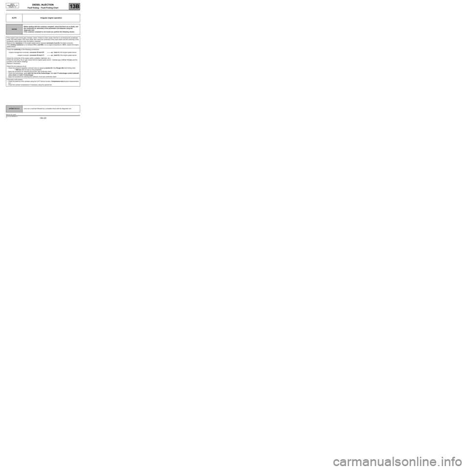
ALP5 Irregular engine operation
NOTESBefore dealing with this customer complaint, check that there are no faults, and
the conformity (or otherwise) of the parameters and statuses using the
diagnostic tool.
If the customer complaint is not ironed out, perform the following checks:
If the engine races during gear changes, check, if there is a floor carpet, that this is not blocking the accelerator
pedal, the brake pedal or the clutch pedal, then check the conformity of the clutch switch and the conformity of the
accelerator pedal sensor when the pedal is released.
Measure the resistance of the engine speed sensor between terminals A and B of its black connector.
If the winding resistance is not between 510 Ω and 850 Ω at an engine temperature of 20˚C, replace the engine
speed sensor.
Check the continuity of the following connections:
–engine management computer, connector B track B1 track A of the engine speed sensor
–engine computer, connector B track C1 track B of the engine speed sensor
Check the conformity of the engine earths (oxidation, tightness, etc.).
Check the mounting, the air gap (check that the engine speed sensor - flywheel gap is 0.5 to 1.8 mm) and the
condition of the sensor (heating).
Replace if necessary.
Check the low pressure circuit.
–Check the pressure regulation solenoid valve by applying section B of the Rough idle fault finding chart.
~ 1600 bar with full load on the accelerator.
–Apply the procedure for checking the air flow; see conformity check.
–Check the turbocharger: apply test 9 Air line at the turbocharger, then test 5 Turbocharger control solenoid
valve check and test 6 Turbocharger.
–Apply the procedure for checking the hydraulic circuit see conformity check.
If the fault is still present:
–Check the balance of the cylinders using the CLIP Technic function, Compression test physical measurements
icon.
–Check the cylinder compressions if necessary using the special tool.
AFTER REPAIRcarry out a road test followed by a complete check with the diagnostic tool.
EDC16_V51_ALP5
Page 241 of 273

DIESEL INJECTION
Fault finding – Test13B
13B -241V3 MR-372-J84-13B250$900.mif
EDC16
PROGRAM No.: C1
Vdiag No.: 51
TEST1 Exhaust system check
Engine stopped: Check that the silencer outlet is
not blocked. Repair or replace the silencer, if
necessary.
Check the seal of the exhaust manifold on the
contact surface between the turbocharger and the
exhaust manifold.
Is the seal in order?
YES
Loosen the catalytic pre-converter on the
turbocharger side. Place a wooden block between
the two parts.
Start the vehicle and check if the engine runs better.
Is the engine running normally?
YES
NORepair or replace the faulty part.
NOThe exhaust pipe is not the cause of the
fault. Continue with the engine fault finding
(see ALP5).
EDC16_V51_TEST1
Page 242 of 273
DIESEL INJECTION
Fault finding – Test13B
13B -242V3 MR-372-J84-13B250$900.mif
EDC16
PROGRAM No.: C1
Vdiag No.: 51
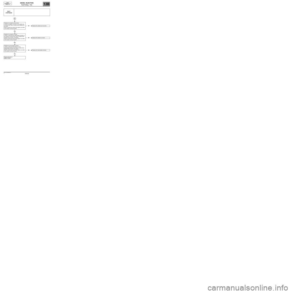
TEST1
CONTINUED
Retighten the catalytic pre-converter.
Loosen the catalytic converter on the catalytic pre-
converter side. Place a wooden block between the
two parts.
Start the vehicle and check if the engine runs better.
Is the engine running normally?
YES
Retighten the catalytic converter.
Loosen or disconnect the intermediate chamber on
the catalytic converter side. Place a wooden block
between the two parts, if necessary.
Start the vehicle and check if the engine runs better.
Is the engine running normally?
YES
Retighten the intermediate chamber.
Loosen or disconnect the silencer on the
intermediate chamber side. Place a wooden block
between the two parts, if necessary.
Start the vehicle and check if the engine runs better.
Is the engine running normally?
YES
Replace the silencer.
END OF TEST1.
NOReplace the catalytic pre-converter.
NOReplace the catalytic converter.
NOReplace the intermediate chamber.
Page 244 of 273

DIESEL INJECTION
Fault finding – Test13B
13B -244V3 MR-372-J84-13B250$900.mif
EDC16
PROGRAM No.: C1
Vdiag No.: 51
TEST2
CONTINUED
Check the condition of the priming bulb, and that it is working properly.
Perform repairs if necessary and continue the test.
If the fault is still present with a low fuel level, check the consistency of the actual fuel level and that indicated on
the instrument panel.
–The transfer pump is supplied via a venturi valve located beneath it.
Check that the opening of the venturi (6 to 8 mm in diameter) is not blocked by dirt contained in the fuel tank.
Check the priming of the low pressure diesel circuit.
Check the conformity of the fuel used by applying test 10 Diesel fuel conformity check.
If the diesel fuel is not correct:
–Replace the diesel fuel.
–Change the diesel filter.
–Bleed the low and high pressure diesel circuit.
Low pressure circuit correct.
END OF TEST2.
Page 245 of 273
DIESEL INJECTION
Fault finding – Test13B
13B -245V3 MR-372-J84-13B250$900.mif
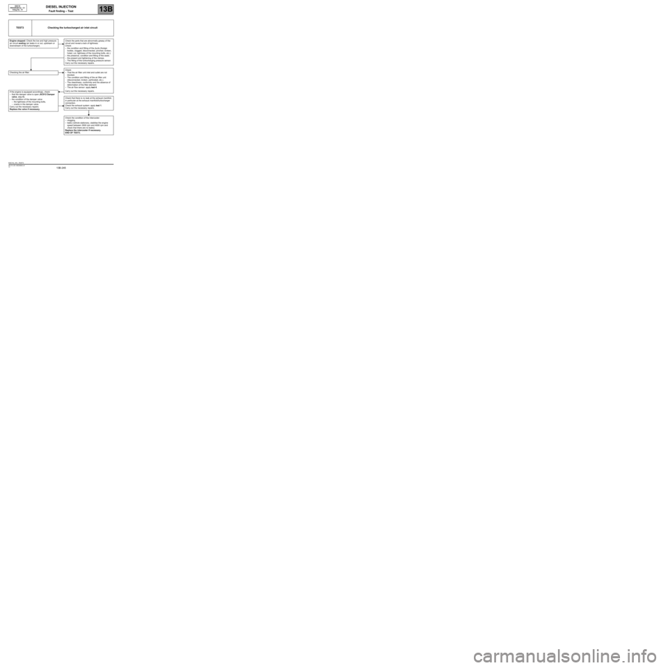
Checking the air filter.
If the engine is equipped accordingly, check:
–that the damper valve is open (AC012 Damper
valve, step B).
–the condition of the damper valve:
–the tightness of the mounting bolts,
–cracks in the damper valve.
Carry out the necessary repairs.
Replace the valve if necessary.
EDC16
PROGRAM No.: C1
Vdiag No.: 51
TEST3 Checking the turbocharged air inlet circuit
Engine stopped: Check the low and high pressure
air circuit sealing (air leaks in or out, upstream or
downstream of the turbocharger).Check the parts that are abnormally greasy of the
circuit and reveal a lack of tightness.
Check:
–the condition and fitting of the ducts (foreign
bodies, clogged, disconnected, pinched, broken,
holed, cut, tightness of the mounting bolts, etc.).
–the presence, condition and fitting of the seals.
–the present and tightening of the clamps.
–The fitting of the turbocharging pressure sensor.
Carry out the necessary repairs.
Check:
–That the air filter unit inlet and outlet are not
blocked.
–The condition and fitting of the air filter unit
(disconnected, broken, perforated, etc.).
–The cleanliness, conformity and the absence of
deformation of the filter element.
–The air flow sensor: apply test 4.
Carry out the necessary repairs.
Check that there is no leak at the exhaust manifold,
in particular at the exhaust manifold/turbocharger
connection.
Check the exhaust system: apply test 1.
Carry out the necessary repairs.
Check the condition of the intercooler:
–clogging,
–leaks (vehicle stationary, stabilise the engine
speed between 3500 rpm and 4000 rpm and
check that there are no leaks).
Replace the intercooler if necessary.
END OF TEST3.
EDC16_V51_TEST3
Page 250 of 273

DIESEL INJECTION
Fault finding – Test13B
13B -250V3 MR-372-J84-13B250$900.mif
EDC16
PROGRAM No.: C1
Vdiag No.: 51
TEST5
CONTINUED 2
Visual inspection of the solenoid valve electrical connector
Switch off the engine.
Note:
The requested checks are entirely visual.
1- Check that the connector is correctly connected and locked.
2- Check that the electric wires are not damaged where they leave the insulation.
Disconnect the connector to continue the checks.
3- Check that there is no heat damage to the unit and mechanical damage to the lock.
4- Check that the contacts (clips and tabs) are not deformed.
5- Check the sealing of the connector.
Do the visual inspections highlight any damage?
NO YES
If there is a repair procedure (see Technical
Note 6015A, Electrical wiring repair, Wiring:
Precautions for repair), repair the connector,
otherwise replace the wiring.
After repair, restart the test from the beginning.
C
1
Page 254 of 273
DIESEL INJECTION
Fault finding – Test13B
13B -254V3 MR-372-J84-13B250$900.mif
EDC16
PROGRAM No.: C1
Vdiag No.: 51
TEST6
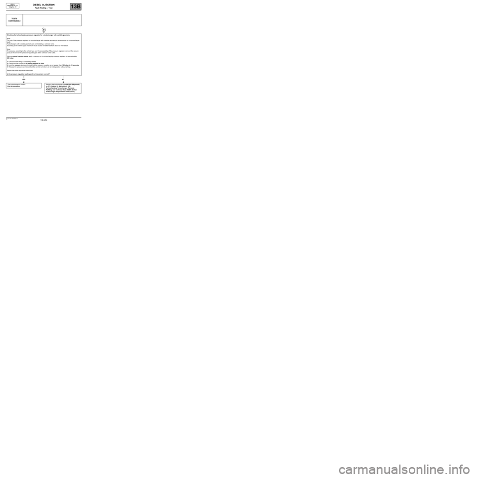
CONTINUED 2
Checking the turbocharging pressure regulator for a turbocharger with variable geometry
Note:
The rod of the pressure regulator on a turbocharger with variable geometry is perpendicular to the turbocharger
shaft.
Turbochargers with variable geometry are controlled by a solenoid valve.
According to the vehicle type, maximum visual access will either be from above or from below.
Note:
If necessary, according to the vehicle type and the accessibility of the pressure regulator, connect the vacuum
pump to the end of the pressure regulator pipe at the solenoid valve outlet.
Using a manual vacuum pump, apply a vacuum on the turbocharging pressure regulator of approximately
650 mbar.
1- Check that the fitting is completely sealed.
2- Check that the control rod is resting against its stop.
3- Lock the vacuum device and check that the pressure variation is not greater than 100 mbar in 10 seconds.
4- Release the pressure and check that the control rod returns to its initial position without jerking.
Repeat the entire sequence three times.
Is the pressure regulator sealing and rod movement correct?
YES NO
The turbocharger is correct.
End of procedure.Replace the turbocharger (see MR 364 (Mégane II)
or 370 (Scénic II), Mechanical, 12B,
Turbocharging, Turbocharger: Removal -
Refitting and Technical Note 3938A, Broken
turbocharger: Replacement instructions).