2009 NISSAN TIIDA e control
[x] Cancel search: e controlPage 4000 of 4331

PG
N
O P
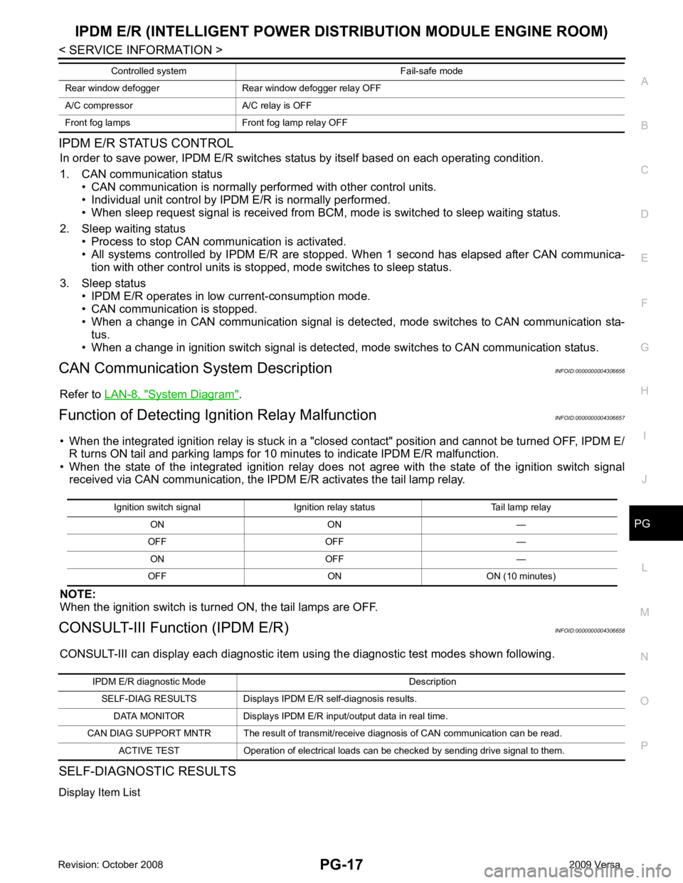
IPDM E/R STATUS CONTROL
In order to save power, IPDM E/R switches status by itself based on each operating condition.
1. CAN communication status • CAN communication is normally performed with other control units.
• Individual unit control by IPDM E/R is normally performed.
• When sleep request signal is received from BCM, mode is switched to sleep waiting status.
2. Sleep waiting status • Process to stop CAN communication is activated.
• All systems controlled by IPDM E/R are stopped. When 1 second has elapsed after CAN communica-
tion with other control units is st opped, mode switches to sleep status.
3. Sleep status • IPDM E/R operates in low current-consumption mode.
• CAN communication is stopped.
• When a change in CAN communication signal is detec ted, mode switches to CAN communication sta-
tus.
• When a change in ignition switch signal is detect ed, mode switches to CAN communication status.
CAN Communication System Description INFOID:0000000004306656
Refer to LAN-8, " System Diagram " .
Function of Detecting Ig nition Relay Malfunction INFOID:0000000004306657
• When the integrated ignition relay is stuck in a "clo sed contact" position and cannot be turned OFF, IPDM E/
R turns ON tail and parking lamps for 10 mi nutes to indicate IPDM E/R malfunction.
• When the state of the integrated ignition relay does not agree with the state of the ignition switch signal
received via CAN communication, the IPDM E/R activates the tail lamp relay.
NOTE:
When the ignition switch is turned ON, the tail lamps are OFF.
CONSULT-III Function (IPDM E/R) INFOID:0000000004306658
CONSULT-III can display each diagnostic item using the diagnostic test modes shown following.
SELF-DIAGNOSTIC RESULTS
Display Item List Rear window defogger Rear window defogger relay OFF
A/C compressor A/C relay is OFF
Front fog lamps Front fog lamp relay OFF Controlled system Fail-safe mode Ignition switch signal Ignition relay status Tail lamp relay
ON ON —
OFF OFF — ON OFF —
OFF ON ON (10 minutes) IPDM E/R diagnostic Mode Description
SELF-DIAG RESULTS Displays IPDM E/R self-diagnosis results.
DATA MONITOR Displays IPDM E/R input/output data in real time.
CAN DIAG SUPPORT MNTR The result of transmit/receive diagnosis of CAN communication can be read. ACTIVE TEST Operation of electrical loads can be checked by sending drive signal to them.
Page 4001 of 4331

Item name
CONSULT-III
screen display Display or unit Monitor item selection
Description
ALL
SIGNALS MAIN
SIGNALS SELECTION
FROM MENU
Motor fan request MOTOR FAN
REQ 1/2/3/4 X X X Signal status input from ECM
Compressor re-
quest AC COMP REQ ON/OFF X X X Signal status input from ECM
Parking, license,
and tail lamp re-
quest TAIL & CLR REQ ON/OFF X X X Signal status input from BCM
Headlamp low
beam request HL LO REQ ON/OFF X X X Signal status input from BCM
Headlamp high
beam request HL HI REQ ON/OFF X X X Signal
status input from BCM
Front fog request FR FOG REQ ON/OFF X X X Signal status input from BCM
FR wiper request FR WIP REQ STOP/1LO/LO/HI X X X Signal status input from BCM
Wiper auto stop WIP AUTO
STOP ACT P/STOP P X X X Output status of IPDM E/R
Wiper protection WIP PROT OFF/LS/HS/Block X X X Control status of IPDM E/R
Starter request ST RLY REQ ON/OFF X X Status of input signal (*1)
Ignition relay
status IGN RLY ON/OFF X X X Ignition relay status monitored
with IPDM E/R
Rear defogger re-
quest RR DEF REQ ON/OFF X X X Signal status input from BCM
Oil pressure
switch OIL P SW OPEN/CLOSE X X
Signal status input from IPDM
E/R
Hood switch HOOD SW (*2) OFF X X Signal status input from IPDM
E/R
Page 4004 of 4331

PG
N
O P
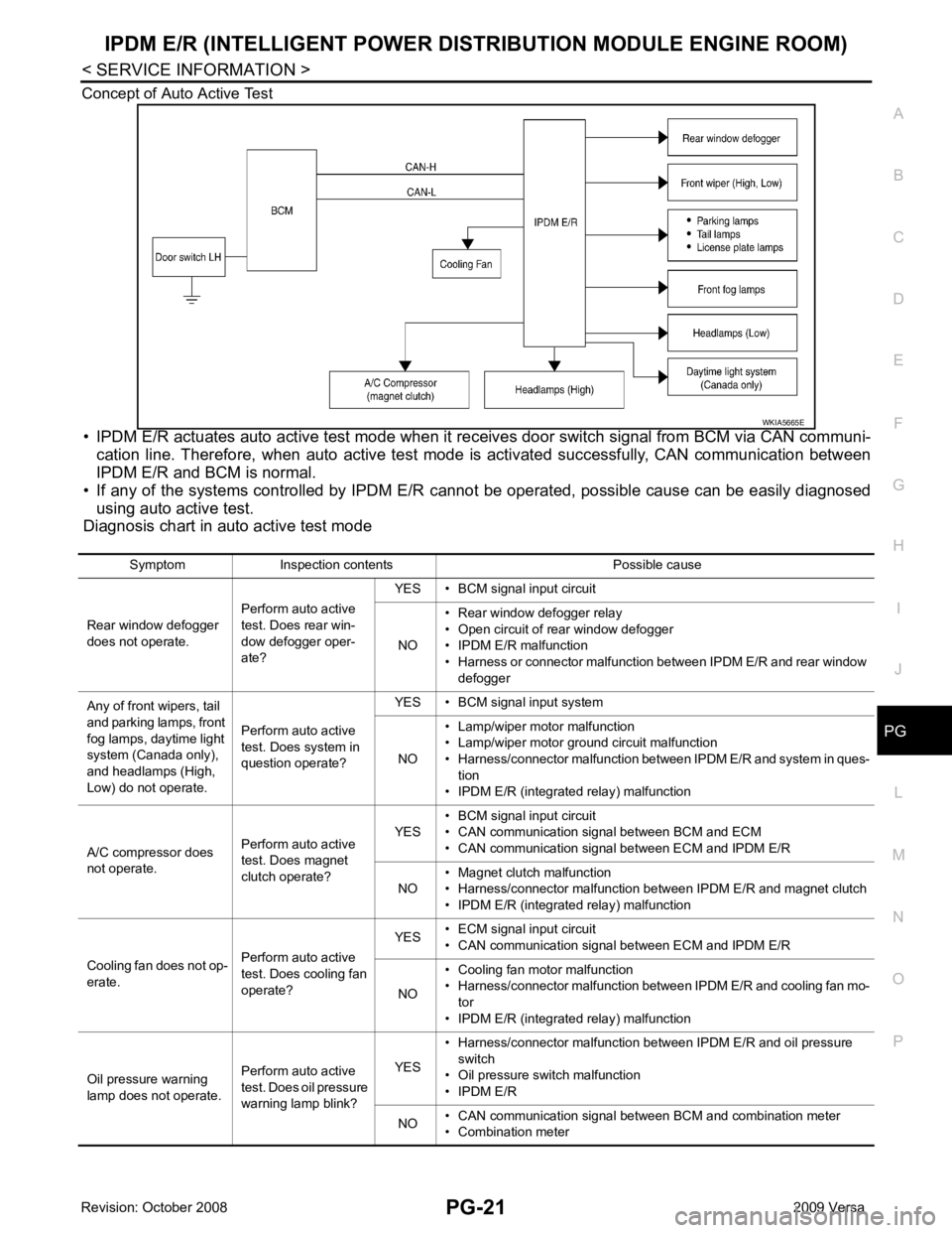
Concept of Auto Active Test
• IPDM E/R actuates auto active test mode when it re ceives door switch signal from BCM via CAN communi-
cation line. Therefore, when auto active test mode is activated successfully, CAN communication between
IPDM E/R and BCM is normal.
• If any of the systems controlled by IPDM E/R cannot be operated, possible cause can be easily diagnosed
using auto active test.
Diagnosis chart in auto active test mode
Page 4008 of 4331

PG
N
O P
24 Y Cooling fan relay-3 Output —
Conditions correct for cooling
fan high operation Battery voltage
Conditions not correct for
cooling fan high operation 0V
26 O Tail lamp relay (park-
ing lamps) Output — Lighting switch in 2nd position Battery voltage
27 BR Tail lamp relay (park-
ing lamps) Output — Lighting switch in 2nd position Battery voltage
28 GR Tail lamp relay (park-
ing lamps) Output — Lighting switch in 2nd position Battery voltage
29 P Tail lamp relay (park-
ing lamps) Output — Lighting switch in 2nd position Battery voltage
30
(A/T
only) R Fuse 54 Output — Ignition switch ON or START Battery voltage
Ignition switch OFF or ACC 0V
31 O Fuse 55 Output — Ignition switch ON or START Battery voltage
Ignition switch OFF or ACC 0V
32 L Wiper high speed sig-
nal OutputON or
START Wiper switch OFF, LO, INT 0V
HI Battery voltage
33 Y Wiper low speed sig-
nal OutputON or
START Wiper switch OFF 0V
LO or INT Battery voltage
35 BR Starter relay (inhibit
switch) InputON or
START Selector lever in "P" or "N"
(CVT or A/T) or clutch pedal
depressed (M/T) Battery voltage
Selector lever any other posi-
tion (CVT or A/T) or clutch
pedal released (M/T) 0V
36 BR Fuel pump relay Output — Ignition switch ON or START Battery voltage
Ignition switch OFF or ACC 0V
37 G Oil pressure switch Input ON or
START Engine running and oil pres-
sure within specification Battery voltage
Engine not running or oil pres-
sure below specification 0V
38 R Wiper auto stop signal Input ON or
START Wipers not in park position Battery voltage
Wipers in park position 0V
39 B Ground Input — — 0V
40 P CAN-L — ON — —
41 L CAN-H — ON — —
45 R Horn relay control Input — Horn switch PUSHED, alarm
switch activated or door lock/
unlock is confirmed when op-
erating lock system via the
keyfob 0V
Horn switch released, alarm
not active, keyfob not active Battery voltage
46 Y Throttle control motor
relay control Input —Ignition switch ON or START 0V
Ignition switch OFF or ACC Battery voltage
47 GR Fuel pump relay con-
trol Input —Ignition switch ON or START 0V
Ignition switch OFF or ACC Battery voltage
Terminal
Wire
color Signal name Signal
input/
output Measuring condition
Reference value
(Approx.)
Ignition
switch Operation or condition
Page 4028 of 4331

PG
N
O P
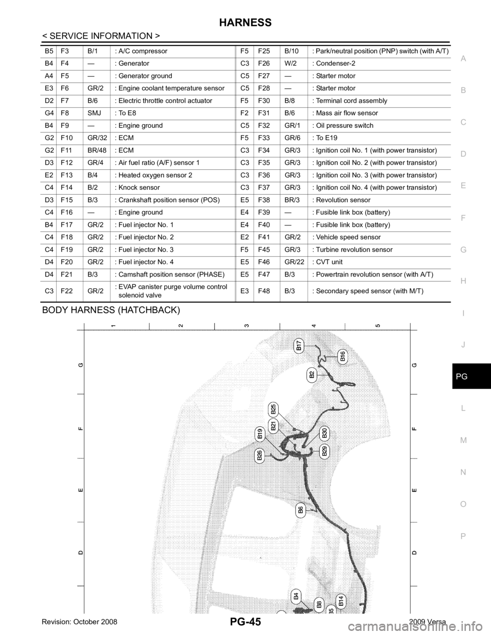
BODY HARNESS (HATCHBACK) B5 F3 B/1 : A/C compressor F5 F25 B/10 : Park/n
eutral position (PNP) switch (with A/T)
B4 F4 — : Generator C3 F26 W/2 : Condenser-2
A4 F5 — : Generator ground C5 F27 — : Starter motor
E3 F6 GR/2 : Engine coolant temperature sensor C5 F28 — : Starter motor
D2 F7 B/6 : Electric throttle control actuator F5 F30 B/8 : Terminal cord assembly
G4 F8 SMJ : To E8 F2 F31 B/6 : Mass air flow sensor
B4 F9 — : Engine ground C5 F32 GR/1 : Oil pressure switch
G2 F10 GR/32 : ECM F5 F33 GR/6 : To E19
G2 F11 BR/48 : ECM C3 F34 GR/3 : Ignition coil No. 1 (with power transistor)
D3 F12 GR/4 : Air fuel ratio (A/F) sensor 1 C3 F35 GR/3 : Ignition coil No. 2 (with power transistor)
E2 F13 B/4 : Heated oxygen sensor 2 C3 F36 GR/3 : Ignition coil No. 3 (with power transistor)
C4 F14 B/2 : Knock sensor C3 F37 GR/3 : Ignition coil No. 4 (with power transistor)
D3 F15 B/3 : Crankshaft position sensor (POS) E5 F38 BR/3 : Revolution sensor
C4 F16 — : Engine ground E4 F39 — : Fusible link box (battery)
B4 F17 GR/2 : Fuel injector No. 1 E4 F40 — : Fusible link box (battery)
C4 F18 GR/2 : Fuel injector No. 2 E2 F41 GR/2 : Vehicle speed sensor
C4 F19 GR/2 : Fuel injector No. 3 F5 F45 GR/3 : Turbine revolution sensor
D4 F20 GR/2 : Fuel injector No. 4 E5 F46 GR/22 : CVT unit
D4 F21 B/3 : Camshaft position sensor (PHASE) E5 F4 7 B/3 : Powertrain revolution sensor (with A/T)
C3 F22 GR/2 : EVAP canister purge volume control
solenoid valve E3 F48 B/3 : Secondary speed sensor (with M/T)
Page 4032 of 4331

PG
N
O P
D3 B100 GR/5 : Fuel level sensor unit and fuel pump C3 B116 W/1 : Rear door switch RH
G5 B101 W/16 : To M12 E3 B117 — : Body ground
G5 B102 W/24 : To M13 B2 B118 Y/2 : RH side curtain air bag module
F3 B103 B/2 : Console power socket D3 B119 W/8 : To D301
A4 B104 GR/3 : EVAP control system pressure sensor G5 B120 W/24 : To M14
A3 B105 B/2 : EVAP canister vent control valve A3 B121 W/32 : Bluetooth control unit
G5 B106 W/4 : To M11 A3 B122 GR/1 : Bluetooth control unit
A2 B107 BR/6 : Rear combination lamp RH D2 B123 B/2 : Rear wheel sensor LH
E4 B108 W/3 : Front door switch RH C3 B124 B/2 : Rear wheel sensor RH
F4 B109 Y/2 : Front RH side air bag module F3 B125 GR/2 : Front console antenna
F4 B110 W/10 : To B300 C3 B126 GR/2 : Rear floor antenna
E5 B111 Y/2 : RH side air bag (satellite) sensor A2 B132 — : Body ground
F4 B112 W/3 : Seat belt buckle switch RH B2 B133 W/2 : To D400
F3 B113 Y/12 : Air bag diagnosis sensor unit A2 B134 W/12 : To D401
E4 B114 — : Body ground E5 B138 B/3 : Belt tension sensor
E4 B115 Y/2 : Front RH seat belt pre-tensioner
Page 4034 of 4331

PG
N
O P
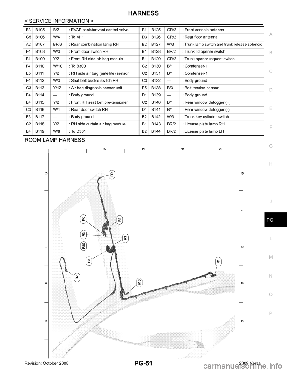
ROOM LAMP HARNESS
B3 B105 B/2 : EVAP canister vent control valve F4 B125 GR/2 : Front console antenna
G5 B106 W/4 : To M11 D3 B126 GR/2 : Rear floor antenna
A2 B107 BR/6 : Rear combination lamp RH B2 B127 W/3 : Trunk lamp switch and trunk release solenoid
F4 B108 W/3 : Front door switch RH B1 B128 BR/2 : Trunk lid opener switch
F4 B109 Y/2 : Front RH side air bag module B1 B129 GR/2 : Trunk opener request switch
F4 B110 W/10 : To B300 C2 B130 B/1 : Condenser-1
E5 B111 Y/2 : RH side air bag (satellite) sensor C2 B131 B/1 : Condenser-1
F4 B112 W/3 : Seat belt buckle switch RH C3 B132 — : Body ground
G3 B113 Y/12 : Air bag diagnosis sensor unit E5 B138 B/3 : Belt tension sensor
E4 B114 — : Body ground D1 B139 — : Body ground
E4 B115 Y/2 : Front RH seat belt pre-tensioner C2 B140 B/1 : Rear window defogger (+)
C3 B116 W/1 : Rear door switch RH D1 B141 B/1 : Rear window defogger (-)
E3 B117 — : Body ground B2 B142 W/3 : Trunk key cylinder switch
C2 B118 Y/2 : RH side curtain air bag module B1 B143 BR/2 : License plate lamp RH
E4 B119 W/8 : To D301 B2 B144 BR/2 : License plate lamp LH
Page 4040 of 4331

PG
N
O P
Wiring Diagram Codes (Cell Codes)
INFOID:0000000004306667
Use the chart below to find out what each wiring diagram code stands for.
Refer to the wiring diagram code in the alphabetical index to find the location (page number) of each wiring
diagram. D4 D405 W/4 : Back door lock assembly C2 D413 B/1 : Rear window defogger (-)
D4 D406 W/2 : Back door request switch F3 D414 — : Body ground
E2 D407 W/2 : High mounted stop lamp Code Section Wiring Diagram Name
ABS BRC Anti-lock Brake System
A/C,M MTC Manual Air Conditioner
APPS1 EC Accelerator Pe dal Position Sensor
A/F EC Air Fuel Ratio Sensor 1
A/FH EC Air Fuel Ratio Sensor 1 Heater
APPS2 EC Accelerator Pe dal Position Sensor
APPS3 EC Accelerator Pe dal Position Sensor
ASC/BS EC ASCD Brake Switch
ASC/SW EC ASCD Steering Switch
ASCBOF EC ASCD Brake Switch
ASCIND EC ASCD Indicator
AT/IND DI A/T Indicator Lamp
AUDIO AV Audio
BACK/L LT Back-up Lamp
BA/FTS AT A/T Fluid Temperature Sensor and TCM Power Supply
B/DOOR BL Back Door Opener
BRK/SW EC Brake Switch
CAN AT CAN Communication Line
CAN CVT CAN Comm unication Line
CAN EC CAN Communication Line
CAN LAN CAN System
CHARGE SC Charging System
CHIME DI Warning Chime
COOL/F EC Cooling Fan Control
COMBSW LT Combination Switch
CVTIND DI CVT Indicator Lamp
D/LOCK BL Power Door Lock
DEF GW Rear Window Defogger
DTRL LT Headlamp - Wi th Daytime Light System
ECTS EC Engine Coolant Temperature Sensor
ENGSS AT Engine Speed Signal
EPS STC Electronic Controlled Power Steering
ETC1 EC Electric Throttle Control Function
ETC2 EC Throttle Control Motor Relay
ETC3 EC Throttle Control Motor
F/FOG LT Front Fog Lamp
F/PUMP EC Fuel Pump
FTS AT A/T Fluid Temperature Sensor
FTS CVT CVT Fluid Temperature Sensor Circuit
FTTS EC Fuel Tank Temperature Sensor
FUEL EC Fuel Ignition System Function
HEATER MTC Heater System