Page 3948 of 4331
MTC
N
O P
INTAKE DOOR
Intake Door Cable Adjustment INFOID:0000000004307082
1. Remove instrument lower finisher. Refer to IP-11 .
2. Remove outer cable of intake door cable (1) from clamp (A).
3. Set intake door lever to REC position.
4. Push intake door link (2) in the direction shown by the arrow, and then carefully pull outer cable to controller side, and install
clamp (A).
5. Operate intake door lever to insure that inner cable moves smoothly.
CAUTION:
When clamping the outer cab le, do not move the inner
cable.
Page 3949 of 4331
.
2. Remove outer cable of air mix door cable (1) from clamp (A).
3. Set temperature control dial to full cold position.
4. Push air mix door lever (2) in the direction shown by arrow, and then carefully pull outer cable toward controller side, and install
clamp (A).
5. Operate temperature control dial to insure that inner cable moves smoothly.
CAUTION:
When clamping the outer cable, do not move the inner
cable.
Page 3950 of 4331
MTC
N
O P
MODE DOOR
Mode Door Cable Adjustment INFOID:0000000004307084
1. Remove glove box assembly and instrument lower cover (RH). Refer to IP-11 .
2. Remove outer cable of mode door cable (1) from clamp (A).
3. Set mode control dial to VENT position.
4. Push main link (2) in the direction shown by the arrow, and then carefully pull outer cable to controller side, and install clamp (A).
5. Operate mode control dial to insure that inner cable moves smoothly.
CAUTION:
When clamping the outer cab le, do not move the inner
cable.
6. Turn mode control dial to each position.
7. Confirm that discharge air comes out accord ing to the air distribution table. Refer to MTC-20, " Discharge
Air Flow " .
Page 3974 of 4331

MTC
N
O P
Check all around the service valves. Ensure service valve caps are secured on the service valves (to
prevent leaks).
NOTE:
After removing A/C manifold gauge set from service va lves, wipe any residue from valves to prevent any
false readings by leak detector.
• Cooling unit (Evaporator)
With engine OFF, turn blower fan on “High” for at least 15 seconds to dissipate any refrigerant trace in
the cooling unit. Wait a minimum of 10 minutes ac cumulation time (refer to the manufacturer’s recom-
mended procedure for actual wait time) before inserting the leak detector probe into the drain hose.
Keep the probe inserted for at least 10 seconds. Use c aution not to contaminate the probe tip with water
or dirt that may be in the drain hose.
5. If a leak detector detects a leak, verify at least once by blowing compressed air into area of suspected
leak, then repeat check as outlined above.
6. Do not stop when one leak is found. Continue to check for additional leaks at all system components.
If no leaks are found, perform steps 7-10.
7. Start engine.
8. Set the heater A/C control as follows;
a. A/C switch: ON
b. Mode control dial position: VENT (Ventilation)
c. Intake door lever position: Recirculation
d. Max. cold temperature
e. Fan speed: High
9. Run engine at 1,500 rpm for at least 2 minutes.
10. Turn engine off and perform leak check again following steps 4 through 6 above.
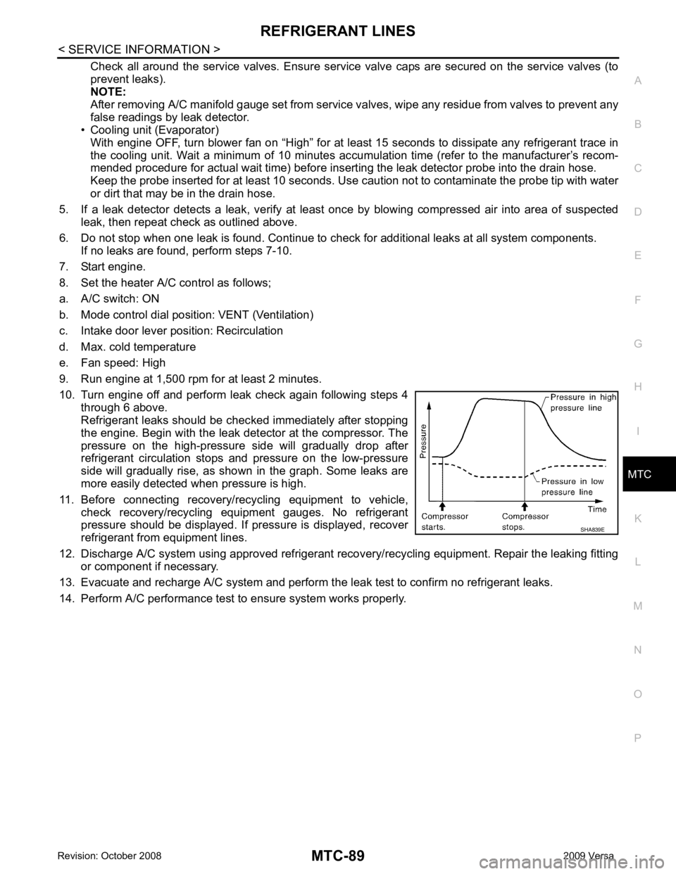
Refrigerant leaks should be chec ked immediately after stopping
the engine. Begin with the leak detector at the compressor. The
pressure on the high-pressure side will gradually drop after
refrigerant circulation stops and pressure on the low-pressure
side will gradually rise, as shown in the graph. Some leaks are
more easily detected when pressure is high.
11. Before connecting recovery/recycling equipment to vehicle, check recovery/recycling equipment gauges. No refrigerant
pressure should be displayed. If pressure is displayed, recover
refrigerant from equipment lines.
12. Discharge A/C system using approved refrigerant reco very/recycling equipment. Repair the leaking fitting
or component if necessary.
13. Evacuate and recharge A/C system and perform the l eak test to confirm no refrigerant leaks.
14. Perform A/C performance test to ensure system works properly.
Page 3976 of 4331

PB
N
O P
CONTENTS
PARKING BRAKE SYSTEM
SERVICE INFORMATION .. ..........................2
PRECAUTIONS .............................................. .....2
Precaution for Supplemental Restraint System
(SRS) "AIR BAG" and "SEAT BELT PRE-TEN-
SIONER" ............................................................. ......
2
Precaution Necessary fo r Steering Wheel Rota-
tion After Battery Disconnect ............................... ......
2
PREPARATION .............................................. .....4 Commercial Service Tool ....................................
.....4
PARKING BRAKE CONTROL ........................... 5
On-Vehicle Service .............................................. .....5
Component .......................................................... .....6
Removal and Installation ..................................... .....6
SERVICE DATA AND SPECIFICATIONS
(SDS) .................................................................. 8
Parking Brake Control ......................................... .....8
Page 3978 of 4331
PB
N
O P
5. When the repair work is completed, return the ignition switch to the
″LOCK ″ position before connecting
the battery cables. (At this time, the steering lock mechanism will engage.)
6. Perform a self-diagnosis check of al l control units using CONSULT-III.
Page 3980 of 4331

PB
N
O P
PARKING BRAKE CONTROL
On-Vehicle Service INFOID:0000000004305223
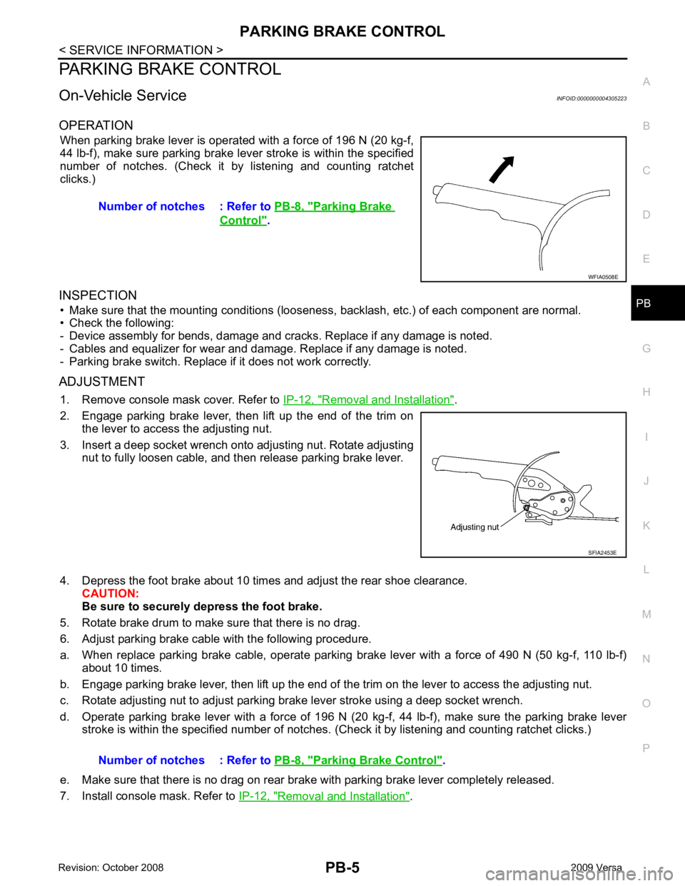
OPERATION When parking brake lever is operated with a force of 196 N (20 kg-f,
44 lb-f), make sure parking brake le ver stroke is within the specified
number of notches. (Check it by listening and counting ratchet
clicks.)
INSPECTION • Make sure that the mounting conditions (looseness, backlash, etc.) of each component are normal.
• Check the following:
- Device assembly for bends, damage and cracks. Replace if any damage is noted.
- Cables and equalizer for wear and damage. Replace if any damage is noted.
- Parking brake switch. Replace if it does not work correctly.
ADJUSTMENT 1. Remove console mask cover. Refer to IP-12, " Removal and Installation " .
2. Engage parking brake lever, then lift up the end of the trim on the lever to access the adjusting nut.
3. Insert a deep socket wrench onto adjusting nut. Rotate adjusting nut to fully loosen cable, and then release parking brake lever.
4. Depress the foot brake about 10 ti mes and adjust the rear shoe clearance.
CAUTION:
Be sure to securely depress the foot brake.
5. Rotate brake drum to make sure that there is no drag.
6. Adjust parking brake cable with the following procedure.
a. When replace parking brake cable, operate parking br ake lever with a force of 490 N (50 kg-f, 110 lb-f)
about 10 times.
b. Engage parking brake lever, then lift up the end of the trim on the lever to access the adjusting nut.
c. Rotate adjusting nut to adjust parking brake lever stroke using a deep socket wrench.
d. Operate parking brake lever with a force of 196 N (20 kg-f, 44 lb-f), make sure the parking brake lever
stroke is within the specified number of notches. (Check it by listening and counting ratchet clicks.)
e. Make sure that there is no drag on rear brake with parking brake lever completely released.
7. Install console mask. Refer to IP-12, " Removal and Installation " .
Number of notches : Refer to
PB-8, " Parking Brake
Control " .
Parking Brake Control " .
Page 3998 of 4331

PG
N
O P
Fuse
INFOID:0000000004306651
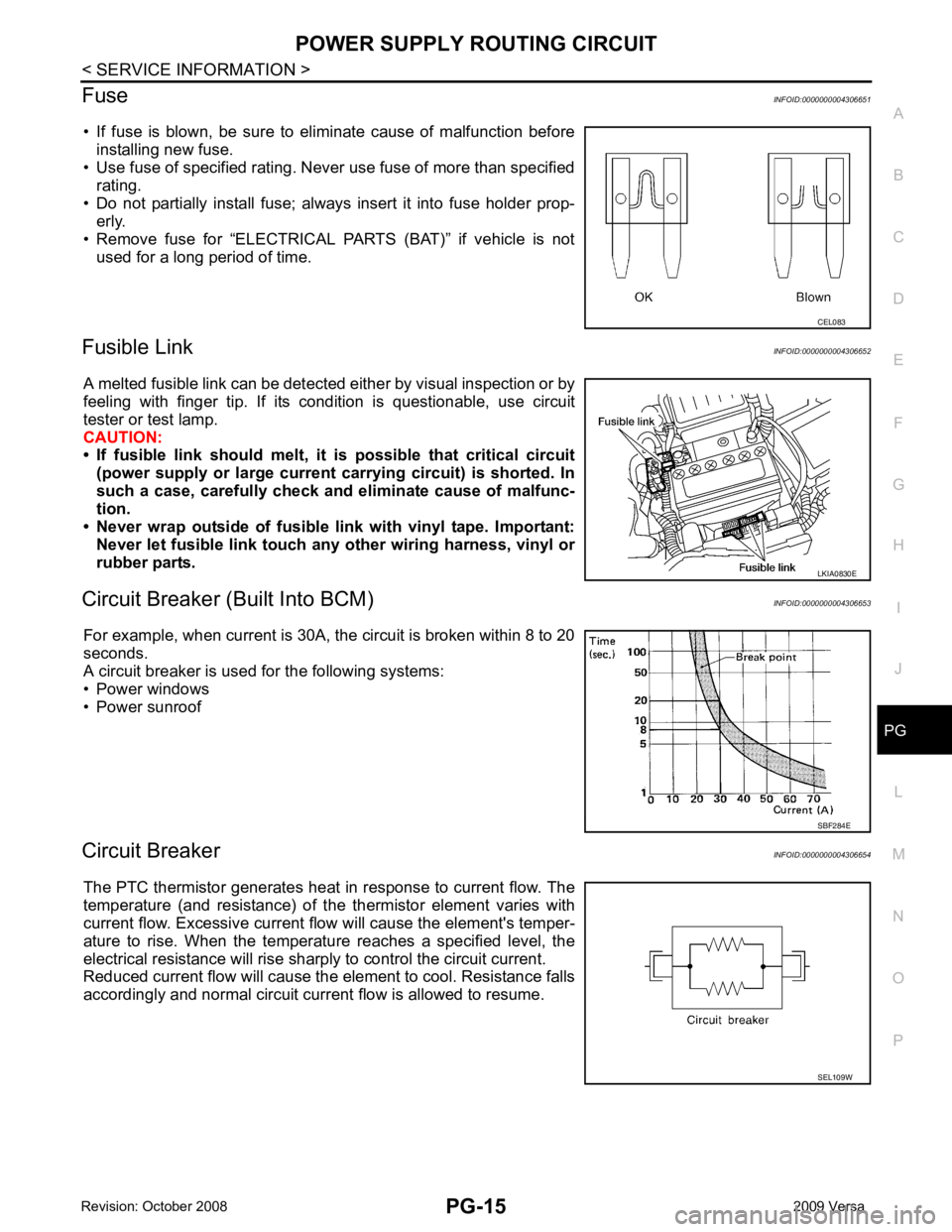
• If fuse is blown, be sure to eliminate cause of malfunction before installing new fuse.
• Use fuse of specified rating. Never use fuse of more than specified
rating.
• Do not partially install fuse; always insert it into fuse holder prop- erly.
• Remove fuse for “ELECTRICAL PARTS (BAT)” if vehicle is not
used for a long period of time.
Fusible Link INFOID:0000000004306652
A melted fusible link can be detected either by visual inspection or by
feeling with finger tip. If its condition is questionable, use circuit
tester or test lamp.
CAUTION:
• If fusible link should melt, it is possible that critical circuit
(power supply or large current carrying circuit) is shorted. In
such a case, carefully check and eliminate cause of malfunc-
tion.
• Never wrap outside of fusible li nk with vinyl tape. Important:
Never let fusible link touch any other wiring harness, vinyl or
rubber parts.
Circuit Breaker (B uilt Into BCM) INFOID:0000000004306653
For example, when current is 30A, the circuit is broken within 8 to 20
seconds.
A circuit breaker is used for the following systems:
• Power windows
• Power sunroof
Circuit Breaker INFOID:0000000004306654
The PTC thermistor generates heat in response to current flow. The
temperature (and resistance) of t he thermistor element varies with
current flow. Excessive current flow will cause the element's temper-
ature to rise. When the temperature reaches a specified level, the
electrical resistance will rise shar ply to control the circuit current.
Reduced current flow will cause the element to cool. Resistance falls
accordingly and normal circuit current flow is allowed to resume. LKIA0830E
SEL109W