2009 NISSAN TIIDA e control
[x] Cancel search: e controlPage 4157 of 4331

SC
N
O P
CHARGING SYSTEM
System Description INFOID:0000000004306825
The generator provides DC voltage to operate the vehicl e's electrical system and to keep the battery charged.
The voltage output is controlled by the IC regulator.
Power is supplied at all times to generator terminal 3 through
• 10A fuse (No. 29, located in the fuse and fusible link box).
Power is supplied through terminal 1 to charge the batte ry and operate the vehicle's electrical system. Output
voltage is monitored at terminal 3 by the IC regulator. The charging circuit is protected by the 120A fusible link
[letter a , located in the fusible link box (battery)].
Ground is supplied
• to generator terminal 5
• through body ground F5, and
• through the generator case to the cylinder block
With the ignition switch in the ON or START position, power is supplied
• through 10A fuse [No. 3, located in the fuse block (J/B)]
• to combination meter terminal 28 for the charge warning lamp.
The IC regulator controls ground to terminal 38 of the combination meter through terminal 2 of the generator.
When the ignition is turned on and power becomes availabl e at terminal 2, this "wakes up" the regulator. The
regulator monitors charge output and grounds terminal 2 or leaves it open depending on charge output. With
power and ground supplied, the charge warning lamp will il luminate. When the generator is providing sufficient
voltage, the ground is opened and the charge warning lamp will go off.
If the charge warning lamp illuminates with the engine running, a malfunction is indicated.
Page 4170 of 4331

SE
N
O P
SILICONE GREASE
Used instead of UHMW tape that will be visible or not fit.
Note: Will only last a few months.
SILICONE SPRAY
Use when grease cannot be applied.
DUCT TAPE
Use to eliminate movement.
CONFIRM THE REPAIR Confirm that the cause of a noise is repaired by test driving the vehicle. Operate the vehicle under the same
conditions as when the noise originally occurred. Refer to the notes on the Diagnostic Worksheet.
Generic Squeak and Rattle Troubleshooting INFOID:0000000004306505
Refer to Table of Contents for specific component removal and installation information.
INSTRUMENT PANEL Most incidents are caused by contact and movement between:
1. The cluster lid A and instrument panel
2. Acrylic lens and combination meter housing
3. Instrument panel to front pillar garnish
4. Instrument panel to windshield
5. Instrument panel mounting pins
6. Wiring harnesses behind the combination meter
7. A/C defroster duct and duct joint
These incidents can usually be located by tapping or moving the components to duplicate the noise or by
pressing on the components while driving to stop the noi se. Most of these incidents can be repaired by apply-
ing felt cloth tape or silicone spray (in hard to reach areas). Urethane pads can be used to insulate wiring har-
ness.
CAUTION:
Do not use silicone spray to isolate a squeak or ra ttle. If you saturate the area with silicone, you will
not be able to recheck the repair.
CENTER CONSOLE Components to pay attention to include:
1. Shifter assembly cover to finisher
2. A/C control unit and cluster lid C
3. Wiring harnesses behind audio and A/C control unit
The instrument panel repair and isolation pr ocedures also apply to the center console.
DOORS Pay attention to the:
1. Finisher and inner panel making a slapping noise
2. Inside handle escutcheon to door finisher
3. Wiring harnesses tapping
4. Door striker out of alignment causing a popping noise on starts and stops
Tapping or moving the components or pressing on them wh ile driving to duplicate the conditions can isolate
many of these incidents. You can usually insulate the ar eas with felt cloth tape or insulator foam blocks from
the NISSAN Squeak and Rattle Kit (J-43980) to repair the noise.
TRUNK Trunk noises are often caused by a loose jack or loose items put into the trunk by the owner.
In addition look for:
1. Trunk lid bumpers out of adjustment
2. Trunk lid striker out of adjustment
3. The trunk lid torsion bars knocking together
4. A loose license plate or bracket
Page 4174 of 4331

SE
N
O P
FRONT SEAT
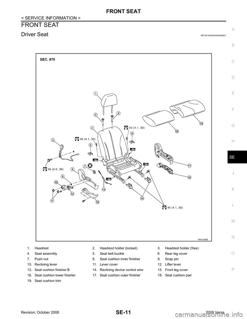
Driver Seat INFOID:0000000004306507
1. Headrest 2. Headrest holder (locked) 3. Headrest holder (free)
4. Seat assembly 5. Seat belt buckle 6. Rear leg cover
7. Push nut 8. Seat cushion inner finisher 9. Snap pin
10. Reclining lever 11. Lever cover 12. Lifter lever
13. Seat cushion finisher B 14. Reclining device control wire 15. Front leg cover
16. Seat cushion lower finisher 17. Seat cushion outer finisher 18. Seat cushion pad
19. Seat cushion trim
Page 4176 of 4331

SE
N
O P
1. Disconnect the negative and positive battery term
inals, then wait at least three minutes.
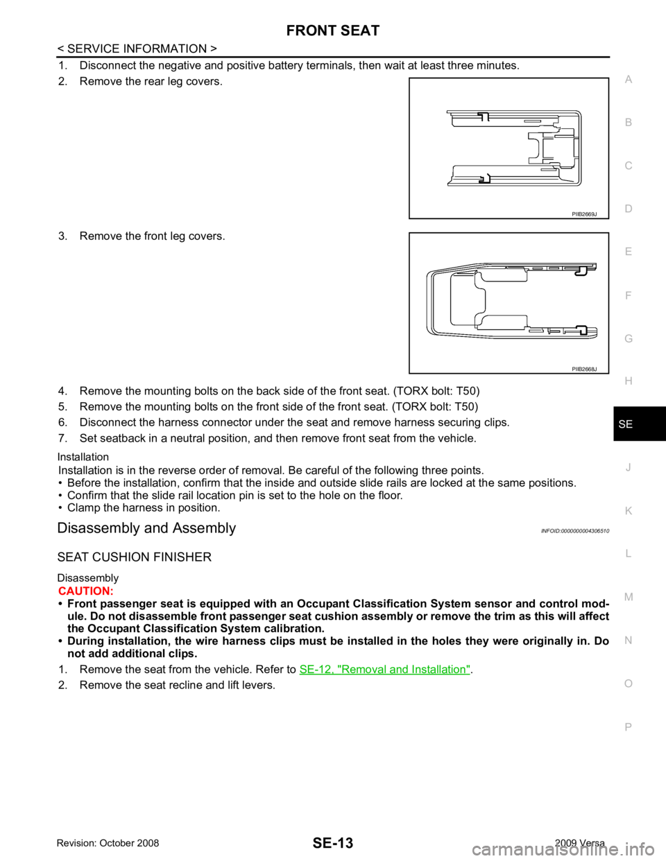
2. Remove the rear leg covers.
3. Remove the front leg covers.
4. Remove the mounting bolts on the back si de of the front seat. (TORX bolt: T50)
5. Remove the mounting bolts on the front side of the front seat. (TORX bolt: T50)
6. Disconnect the harness connector under the seat and remove harness securing clips.
7. Set seatback in a neutral position, and t hen remove front seat from the vehicle.
Installation Installation is in the reverse order of removal. Be careful of the following three points.
• Before the installation, confirm that the inside and outside slide rails are locked at the same positions.
• Confirm that the slide rail location pin is set to the hole on the floor.
• Clamp the harness in position.
Disassembly and Assembly INFOID:0000000004306510
SEAT CUSHION FINISHER
Disassembly CAUTION:
• Front passenger seat is equipped with an Occu pant Classification System sensor and control mod-
ule. Do not disassemble front passenger seat cushion assembly or remove the trim as this will affect
the Occupant Classificatio n System calibration.
• During installation, the wire harn ess clips must be installed in the holes they were originally in. Do
not add additional clips.
1. Remove the seat from the vehicle. Refer to SE-12, " Removal and Installation " .
2. Remove the seat recline and lift levers. PIIB2668J
Page 4191 of 4331

SRS
N
O P
CONTENTS
SUPPLEMENTAL RESTRAINT SYSTEM (SRS)
PRECAUTION ....... ........................................2
PRECAUTIONS .............................................. .....2
Precaution for Supplemental Restraint System
(SRS) "AIR BAG" and "SEAT BELT PRE-TEN-
SIONER" ............................................................. ......
2
Precaution for SRS "AIR BAG" and "SEAT BELT
PRE-TENSIONER" Service ................................ ......
2
Precaution Necessary fo r Steering Wheel Rota-
tion After Battery Disconnect ............................... ......
2
Occupant Classification System Precaution ....... ......3
SYMPTOM DIAGNOSIS ..... ..........................4
SUPPLEMENTAL RESTRAINT SYSTEM
(SRS) .............................................................. .....
4
SRS Configuration .............................................. ......4
Driver Air Bag Module ......................................... ......5
Front Passenger Air Bag Module ..............................5
Front Side Air Bag ............................................... ......5
Side Curtain Air Bag ............................................ ......5
Front Seat Belt Pre-tensioner with Load Limiter . ......6
Occupant Classification System (OCS) .............. ......6
Direct-connect SRS Component Connectors ...... ......7
TROUBLE DIAGNOSIS ................................. .....8
Trouble Diagnosis Introduction ........................... ......8
SRS Component Parts Location ......................... ....10
Schematic ........................................................... ....11
Wiring Diagram - SRS- ........................................ ....12
CONSULT-III Function (AIR BAG) ...................... ....17
Self-Diagnosis Function (Without CONSULT-III) .... 18
SRS Operation Check ......................................... ....19
Trouble Diagnosis with CONSULT-III ................. ....20
Trouble Diagnosis without CONSULT-III ............ ....28
Trouble Diagnosis: "AIR BAG" Warning Lamp
Does Not Turn Off ............................................... ....
31 Trouble Diagnosis: "AIR BAG" Warning Lamp
Does Not Turn On ............................................... ....
32
ON-VEHICLE REPAIR ..... ............................34
DRIVER AIR BAG MODULE ............................ 34
Removal and Installation ..................................... ....34
SPIRAL CABLE ................................................ 37
Removal and Installation ..................................... ....37
FRONT PASSENGER AIR BAG MODULE ...... 39
Removal and Installation ..................................... ....39
SIDE CURTAIN AIR BAG MODULE ................ 40
Component .......................................................... ....40
Removal and Installation ..................................... ....40
CRASH ZONE SEN SOR ................................... 42
Removal and Installation ..................................... ....42
SIDE AIR BAG (SATELLITE) SENSOR ........... 43
Removal and Installation ..................................... ....43
FRONT SEAT BELT PRE-TENSIONER ........... 44
Removal and Installation ..................................... ....44
DIAGNOSIS SENSOR UNIT ............................. 45
Removal and Installation ..................................... ....45
OCCUPANT CLASSIFICATION SYSTEM
CONTROL UNIT ................................................ 46
Removal and Installation ..................................... ....46
COLLISION DIAGNOSIS .................................. 47
For Frontal Collision ............................................ ....47
For Side and Rollover Colli sion ...............................48
Page 4193 of 4331

SRS
N
O P
OPERATION PROCEDURE
1. Connect both battery cables. NOTE:
Supply power using jumper cables if battery is discharged.
2. Use the Intelligent Key or mechanical key to turn the ignition switch to the ″ACC ″ position. At this time, the
steering lock will be released.
3. Disconnect both battery cables. The steering lock will remain released and the steering wheel can be
rotated.
4. Perform the necessary repair operation.
5. When the repair work is completed, return the ignition switch to the ″LOCK ″ position before connecting
the battery cables. (At this time, the steering lock mechanism will engage.)
6. Perform a self-diagnosis check of al l control units using CONSULT-III.
Occupant Classification System Precaution INFOID:0000000004307174
Replace control unit and passenger front seat cushion as an assembly.
Page 4213 of 4331
![NISSAN TIIDA 2009 Service Repair Manual SRS
N
O P
CURTAIN MODULE LH
[OPEN][B1150] The LH side curtain air bag module circuit is open. 1. Visually check the wiring harness
connection.
2. Replace the harness if it has visi- ble damage.
3. Re NISSAN TIIDA 2009 Service Repair Manual SRS
N
O P
CURTAIN MODULE LH
[OPEN][B1150] The LH side curtain air bag module circuit is open. 1. Visually check the wiring harness
connection.
2. Replace the harness if it has visi- ble damage.
3. Re](/manual-img/5/57398/w960_57398-4212.png)
SRS
N
O P
CURTAIN MODULE LH
[OPEN][B1150] The LH side curtain air bag module circuit is open. 1. Visually check the wiring harness
connection.
2. Replace the harness if it has visi- ble damage.
3. Replace LH side curtain air bag module.
4. Replace the air bag diagnosis
sensor unit.
5. Replace the related harness.
CURTAIN MODULE LH
[VB-SHORT]
[B1151] The LH side curtain air bag module circuit is shorted to some
power supply circuits.
CURTAIN MODULE LH [GND-SHORT][B1152] The LH side curtain air bag module circuit is shorted to
ground.
CURTAIN MODULE LH [SHORT][B1153] The circuits for the LH side curtain air bag module are shorted
to each other.
CURTAIN MODULE RH [OPEN]
[B1145] The RH side curtain air bag module circuit is open. 1. Visually check the wiring harness
connection.
2. Replace the harness if it has visi- ble damage.
3. Replace RH side curtain air bag
module.
4. Replace the air bag diagnosis sensor unit.
5. Replace the related harness.
CURTAIN MODULE RH
[VB-SHORT][B1146] The RH side curtain air bag module circuit is shorted to some
power supply circuits.
CURTAIN MODULE RH [GND-SHORT][B1147] The RH side curtain air bag module circuit is shorted to
ground.
CURTAIN MODULE RH [SHORT]
[B1148] The circuits for the RH side curtain air bag module are shorted
to each other.
CONTROL UNIT [B1XXX] Air bag diagnosis sensor unit is malfunctioning. 1. Visually check the wiring harness
connection.
2. Replace the air bag diagnosis
sensor unit.
OCCUPANT SENS C/U [UNIT FAIL]
[B1017], [B1020] or [B1021] Occupant classification system is malfunctioning. 1. Replace RH front seat cushion/
occupant classification system
control unit assembly.
OCCUPANT SENS C/U [COMM FAIL][B1022] Communication between the occupant classification system
control unit and air bag diagnosis sensor unit is interrupted. 1. Visually check the wiring harness
connection.
2. Replace the harness if it has visi- ble damage.
3. Replace RH front seat cushion/ occupant classification system
control unit assembly.
4. Replace the air bag diagnosis
sensor unit.
5. Replace the related harness.
OCCUPANT SENS [UNIT FAIL]
[B1018] Occupant classification sensor is malfunctioning. 1. Replace RH front seat cushion/
occupant classification system
control unit assembly.
BELT TENSION SENS [UNIT FAIL][B1019] Belt tension sensor is malfunctioning. 1. Visually check the wiring harness
connection.
2. Replace the harness if it has visi-
ble damage.
3. Replace RH front seat belt as- sembly.
4. Replace RH front seat cushion/ occupant classification system
control unit assembly.
Diagnostic item Explanation
Repair order
Recheck SRS at each replacement
Page 4217 of 4331
![NISSAN TIIDA 2009 Service Repair Manual SRS
N
O P
PRE-TEN FRONT LH
[OPEN]
[B1086] The circuit for front LH seat belt pre-tensioner is open. 1. Visually check the wiring harness
connections.
2. Replace the harness if it has visi- ble damag NISSAN TIIDA 2009 Service Repair Manual SRS
N
O P
PRE-TEN FRONT LH
[OPEN]
[B1086] The circuit for front LH seat belt pre-tensioner is open. 1. Visually check the wiring harness
connections.
2. Replace the harness if it has visi- ble damag](/manual-img/5/57398/w960_57398-4216.png)
SRS
N
O P
PRE-TEN FRONT LH
[OPEN]
[B1086] The circuit for front LH seat belt pre-tensioner is open. 1. Visually check the wiring harness
connections.
2. Replace the harness if it has visi- ble damage.
3. Replace front LH seat belt pre- tensioner.
4. Replace the air bag diagnosis
sensor unit.
5. Replace the related harness.
PRE-TEN FRONT LH
[VB-SHORT]
[B1087] The circuit for front LH seat belt pre-tensioner is shorted to
some power supply circuit.
PRE-TEN FRONT LH [GND-SHORT] [B1088] The circuit for front LH seat belt pre-tensioner is shorted to
ground.
PRE-TEN FRONT LH [SHORT][B1089] The circuits for the front LH seat belt pre-tensioner are shorted
to each other.
PRE-TEN FRONT RH [OPEN]
[B1081] The circuit for front RH seat belt pre-tensioner is open. 1. Visually check the wiring harness
connections.
2. Replace the harness if it has visi- ble damage.
3. Replace front RH seat belt pre-
tensioner.
4. Replace the air bag diagnosis sensor unit.
5. Replace the related harness.
PRE-TEN FRONT RH
[VB-SHORT][B1082] The circuit for front RH seat belt pre-tensioner is shorted to
some power supply circuit.
PRE-TEN FRONT RH [GND-SHORT][B1083] The circuit for front RH seat belt pre-tensioner is shorted to
ground.
PRE-TEN FRONT RH [SHORT]
[B1084] The circuits for the front RH seat belt pre-tensioner are short-
ed to each other.
CURTAIN MODULE LH [OPEN][B1150] The LH side curtain air bag module circuit is open. 1. Visually check the wiring harness
connection.
2. Replace the harness if it has visi-
ble damage.
3. Replace LH side curtain air bag module.
4. Replace the air bag diagnosis sensor unit.
5. Replace the related harness.
CURTAIN MODULE LH
[VB-SHORT][B1151] The LH side curtain air bag module circuit is shorted to some
power supply circuits.
CURTAIN MODULE LH [GND-SHORT]
[B1152] The LH side curtain air bag module circuit is shorted to
ground.
CURTAIN MODULE LH [SHORT][B1153] The circuits for the LH side curtain air bag module are shorted
to each other.
CURTAIN MODULE RH [OPEN]
[B1145] The RH side curtain air bag module circuit is open. 1. Visually check the wiring harness
connection.
2. Replace the harness if it has visi- ble damage.
3. Replace RH side curtain air bag
module.
4. Replace the air bag diagnosis sensor unit.
5. Replace the related harness.
CURTAIN MODULE RH
[VB-SHORT][B1146] The RH side curtain air bag module circuit is shorted to some
power supply circuits.
CURTAIN MODULE RH [GND-SHORT][B1147] The RH side curtain air bag module circuit is shorted to
ground.
CURTAIN MODULE RH [SHORT]
[B1148] The circuits for the RH side curtain air bag module are shorted
to each other.
CONTROL UNIT [B1XXX] Air bag diagnosis sensor unit is malfunctioning. 1. Visually check the wiring harness
connection.
2. Replace the air bag diagnosis
sensor unit.
OCCUPANT SENS C/U [UNIT FAIL]
[B1017], [B1020] or [B1021] Occupant classification system is malfunctioning. 1. Replace RH front seat cushion/
occupant classification system
control unit assembly.
Diagnostic item Explanation
Repair order
Recheck SRS at each replacement