Page 4253 of 4331

STC
N
O P
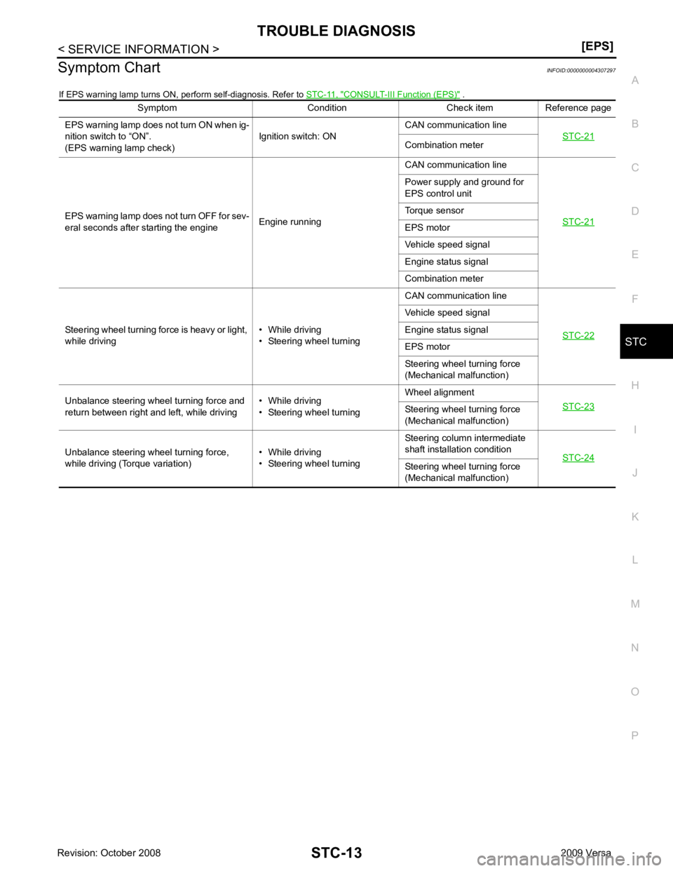
Symptom Chart
INFOID:0000000004307297
If EPS warning lamp turns ON, perform self-diagnosis. Refer to STC-11, " CONSULT-III Function (EPS) " .
Symptom Condition Check item Reference page
EPS warning lamp does not turn ON when ig-
nition switch to “ON”.
(EPS warning lamp check) Ignition switch: ONCAN communication line
STC-21 Combination meter
EPS warning lamp does not turn OFF for sev-
eral seconds after starting the engine Engine runningCAN communication line
STC-21 Power supply and ground for
EPS control unit
Torque sensor
EPS motor
Vehicle speed signal
Engine status signal
Combination meter
Steering wheel turning force is heavy or light,
while driving • While driving
• Steering wheel turning CAN communication line
STC-22 Vehicle speed signal
Engine status signal
EPS motor
Steering wheel turning force
(Mechanical malfunction)
Unbalance steering wheel turning force and
return between right and left, while driving • While driving
• Steering wheel turning Wheel alignment
STC-23 Steering wheel
turning force
(Mechanical malfunction)
Unbalance steering wheel turning force,
while driving (Torque variation) • While driving
• Steering wheel turning Steering column intermediate
shaft installation condition STC-24 Steering wheel
turning force
(Mechanical malfunction)
Page 4254 of 4331
EPS Terminal and Reference Value " .
DIAGNOSTIC PROCEDURE OK >> GO TO 2.
NG >> Check the following. If any items are damaged, repair or replace damaged parts. • 60 A fusible link (No. m, located in the fuse and fusible link block). Refer to PG-3 .
• 10 A fuse [No. 2, located in the fuse block (J/B)]. Refer to PG-3 .
• Harness for short or open between battery and EPS control unit harness connector M54 termi-
nal 17.
• Harness for short or open between ignition switch and EPS control unit harness connector M53
terminal 10. Connector Terminal Voltage
M53 10 – Ground Battery voltage
M54 17 – Ground Battery voltage
Page 4255 of 4331

STC
N
O P
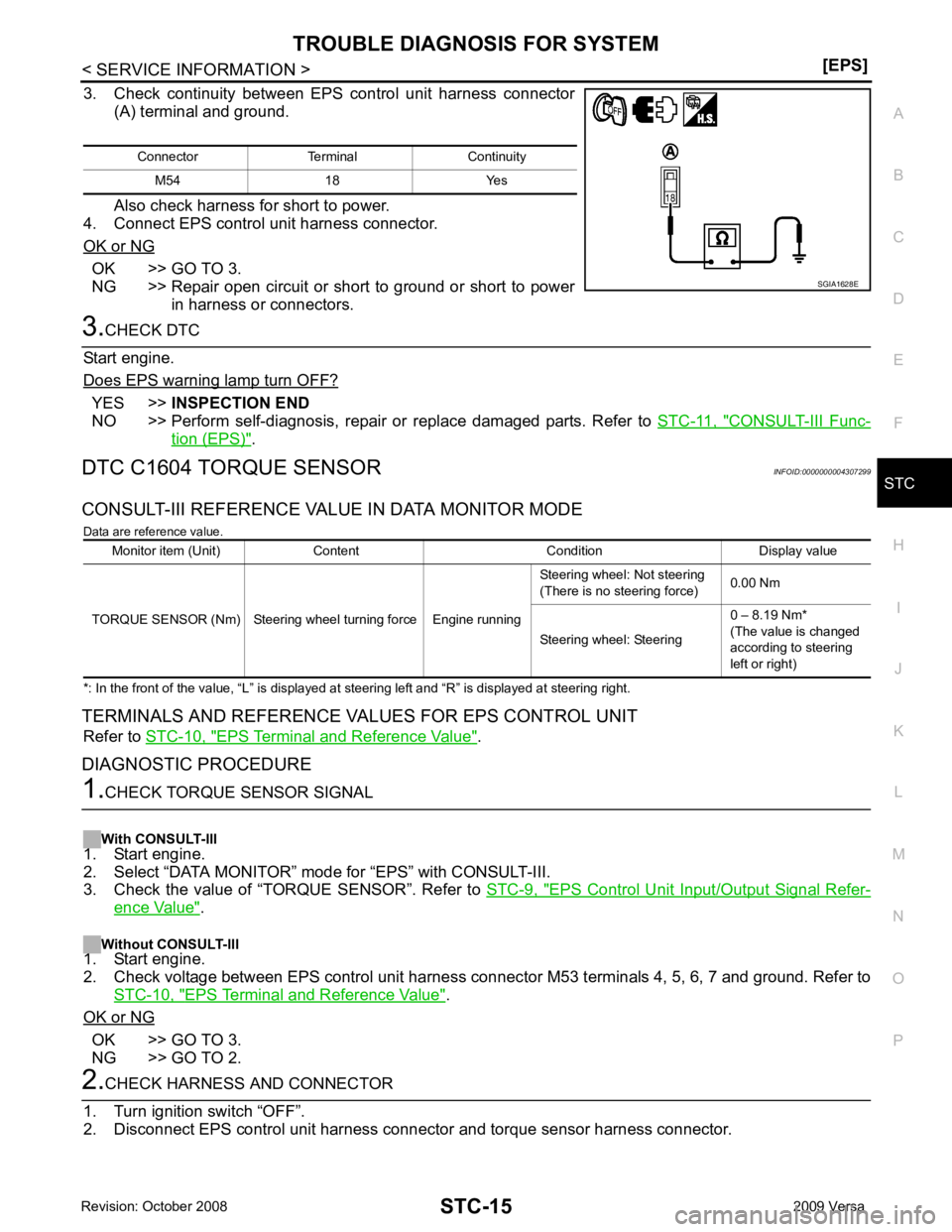
3. Check continuity between EPS control unit harness connector
(A) terminal and ground.
Also check harness for short to power.
4. Connect EPS control unit harness connector.
OK or NG OK >> GO TO 3.
NG >> Repair open circuit or short to ground or short to power
in harness or connectors. YES >>
INSPECTION END
NO >> Perform self-diagnosis, repair or replace damaged parts. Refer to STC-11, " CONSULT-III Func-
tion (EPS) " .
DTC C1604 TORQUE SENSOR INFOID:0000000004307299
CONSULT-III REFERENCE VALUE IN DATA MONITOR MODE Data are reference value.
*: In the front of the value, “L” is displayed at steering left and “R” is displayed at steering right.
TERMINALS AND REFERENCE VA LUES FOR EPS CONTROL UNIT
Refer to STC-10, " EPS Terminal and Reference Value " .
DIAGNOSTIC PROCEDURE EPS Control Unit Input/Output Signal Refer-
ence Value " .
Without CONSULT-III
1. Start engine.
2. Check voltage between EPS control unit harness connec tor M53 terminals 4, 5, 6, 7 and ground. Refer to
STC-10, " EPS Terminal and Reference Value " .
OK or NG OK >> GO TO 3.
NG >> GO TO 2.
Page 4256 of 4331
OK >> GO TO 3.
NG >> Repair or replace damaged parts. EPS Control Unit Input/Output Signal Reference
Value " .
OK or NG OK >> GO TO 4.
NG >> Check EPS control unit pin terminals for dam age or loose connection with harness connector. If
any items are damaged, repair or replace damaged parts. OK >>
INSPECTION END
NG >> Torque sensor is malfunctioning. Replace steering column assembly. Refer to PS-9, " Removal
and Installation " .
DTC C1606 EPS MOTOR INFOID:0000000004307300
CONSULT-III REFERENCE VALUE IN DATA MONITOR MODE
Data are reference value.
* : Almost in accordance with the value of “MOTOR SIG”. It is not a malfunction though these values are not accorded when steer ing
quickly.
TERMINALS AND REFERENCE VALUES FOR EPS CONTROL UNIT
Refer to STC-10, " EPS Terminal and Reference Value " .
DIAGNOSTIC PROCEDURE
Page 4257 of 4331
STC
N
O P
With CONSULT-III
1. Start engine.
2. Select “DATA MONITOR” mode for “EPS” with CONSULT-III.
3. Check the values of “MOTOR SIG” and “MOTOR CURRENT”. Refer to STC-9, " EPS Control Unit Input/
Output Signal Reference Value " .
OK or NG OK >> GO TO 3.
NG >> GO TO 2. OK >> GO TO 3.
NG >> EPS motor is malfunctioning. Replace steering column
assembly. Refer to PS-9, " Removal and Installation " .
EPS Control Unit Input/Output Signal Reference
Value " .
OK or NG OK >> GO TO 4.
NG >> Check EPS control unit pin terminals for damage or loose connection with harness connector. If
any items are damaged, repair or replace damaged parts. OK >>
INSPECTION END
NG >> GO TO 3.
DTC C1607 EEPROM INFOID:0000000004307301
DIAGNOSTIC PROCEDURE “ EEPROM [C1607] ” displayed?
YES >> Replace EPS control unit. Refer to
PS-9, " Removal and Installation " .
NO >> INSPECTION END
DTC C1608 CONTROL UNIT INFOID:0000000004307302
DIAGNOSTIC PROCEDURE
Page 4258 of 4331
![NISSAN TIIDA 2009 Service Repair Manual “ CONTROL UNIT [C1608] ” displayed?
YES >> Replace EPS control unit. Refer to
PS-9, " Removal and Installation " .
NO >> INSPECTION END
DTC C1609 CAN VHCL SPEED INFOID:0000000004307303
CONSULT-I NISSAN TIIDA 2009 Service Repair Manual “ CONTROL UNIT [C1608] ” displayed?
YES >> Replace EPS control unit. Refer to
PS-9, " Removal and Installation " .
NO >> INSPECTION END
DTC C1609 CAN VHCL SPEED INFOID:0000000004307303
CONSULT-I](/manual-img/5/57398/w960_57398-4257.png)
“ CONTROL UNIT [C1608] ” displayed?
YES >> Replace EPS control unit. Refer to
PS-9, " Removal and Installation " .
NO >> INSPECTION END
DTC C1609 CAN VHCL SPEED INFOID:0000000004307303
CONSULT-III REFERENCE VALUE IN DATA MONITOR MODE
Data are reference value.
* : It is not a malfunction, though it might not be corresponding just after ignition switch is turned ON.
DIAGNOSTIC PROCEDURE CONSULT-III Function (METER/M&A) " .
Is any malfunction detec ted by self-diagnosis?YES >> Check the malfunctioning system.
NO-1 >> With ABS: GO TO 2.
NO-2 >> Without ABS: GO TO 3. CONSULT-III
Function (ABS) " .
Is any malfunction detec ted by self-diagnosis?YES >> Check the malfunctioning system.
NO >> GO TO 4. CONSULT-III Function (TRANSMISSION) " .
Is any malfunction detec ted by self-diagnosis?YES >> Check the malfunctioning system.
NO >> GO TO 4. EPS Control Unit Input/Output Signal Reference
Value " .
OK or NG OK >> GO TO 5.
NG >> Check EPS control unit pin terminals for dam age or loose connection with harness connector. If
any items are damaged, repair or replace damaged parts.
Page 4259 of 4331

STC
N
O P
OK >>
INSPECTION END
NG >> Perform self-diagnosis with ABS actuator and el ectric unit (control unit) and combination meter.
Refer to BRC-18, " CONSULT-III Function (ABS) " ,
DI-12, " CONSULT-III Function (METER/M&A) "
.
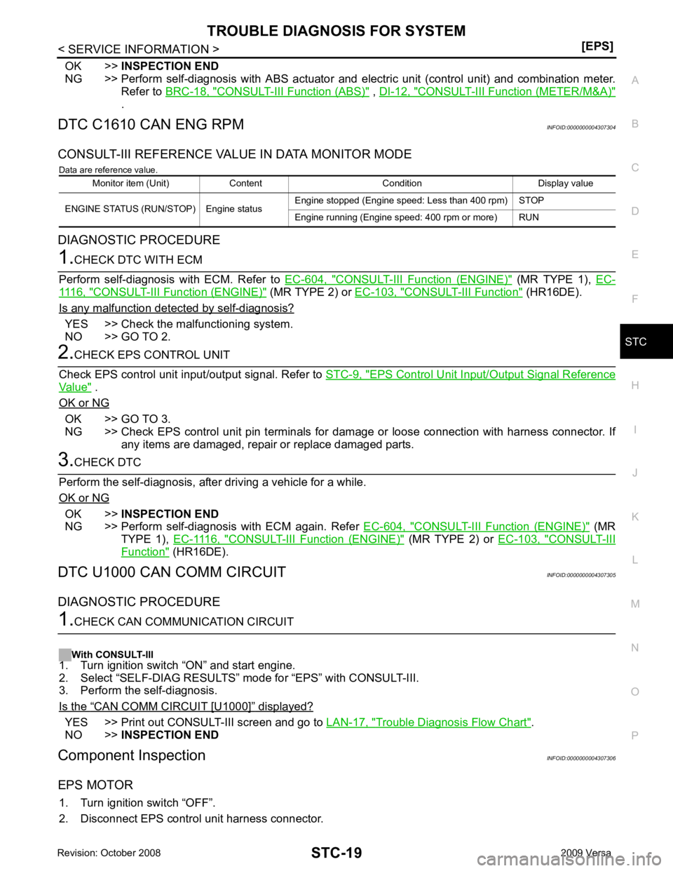
DTC C1610 CAN ENG RPM INFOID:0000000004307304
CONSULT-III REFERENCE VALUE IN DATA MONITOR MODE Data are reference value.
DIAGNOSTIC PROCEDURE CONSULT-III Function (ENGINE) " (MR TYPE 1),
EC-1116, " CONSULT-III F
unction (ENGINE) " (MR TYPE 2) or
EC-103, " CONSULT-III Function " (HR16DE).
Is any malfunction detected by self-diagnosis? YES >> Check the malfunctioning system.
NO >> GO TO 2. EPS Control Unit Input/Output Signal Reference
Value " .
OK or NG OK >> GO TO 3.
NG >> Check EPS control unit pin terminals for damage or loose connection with harness connector. If
any items are damaged, repair or replace damaged parts. OK >>
INSPECTION END
NG >> Perform self-diagnosis with ECM again. Refer EC-604, " CONSULT-III Function (ENGINE) " (MR
TYPE 1), EC-1116, " CONSULT-III Function (ENGINE) " (MR TYPE 2) or
EC-103, " CONSULT-III
Function " (HR16DE).
DTC U1000 CAN COMM CIRCUIT INFOID:0000000004307305
DIAGNOSTIC PROCEDURE “ CAN COMM CIRCUIT [U1000] ” displayed?
YES >> Print out CONSULT-III screen and go to
LAN-17, " Trouble Diagnosis Flow Chart " .
NO >> INSPECTION END
Component Inspection INFOID:0000000004307306
EPS MOTOR 1. Turn ignition switch “OFF”.
2. Disconnect EPS control unit harness connector. Monitor item (Unit) Content Condition Display value
ENGINE STATUS (RUN/STOP) Engine status Engine stopped (Engine speed: Less than 400 rpm) STOP
Engine running (Engine speed: 400 rpm or more) RUN
Page 4260 of 4331
STC-20< SERVICE INFORMATION >
[EPS]
TROUBLE DIAGNOSIS FOR SYSTEM
3. Check resistance between EPS control unit harness connector
(A) terminals.
4. If NG, replace the steering column assembly. Refer to PS-9," Removal and Installation " .
Connector Terminal Resistance
M60 19 – 20 Approx. 0.1 Ω or less SGIA1630E