2009 NISSAN TIIDA wiper
[x] Cancel search: wiperPage 445 of 4331
BCS
N
O P
BCM (BODY CONTROL MODULE)
System Description INFOID:0000000004306833
BCM (body control module) controls the operation of various electrical units installed on the vehicle.
BCM FUNCTION BCM has a combination switch reading function for reading the operation of combination switches (light, wiper,
washer, turn signal) in addition to the function for c ontrolling the operation of various electrical components.
Also, it functions as an interface that receives signal s from the front air control, and sends signals to ECM
using CAN communication.
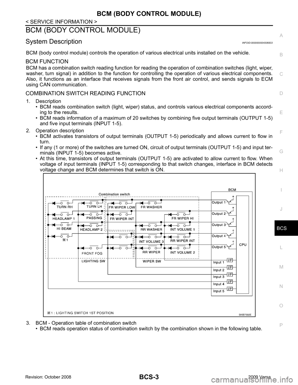
COMBINATION SWITCH READING FUNCTION 1. Description • BCM reads combination switch (light, wiper) status , and controls various electrical components accord-
ing to the results.
• BCM reads information of a maximum of 20 switches by combining five output terminals (OUTPUT 1-5)
and five input terminals (INPUT 1-5).
2. Operation description • BCM activates transistors of output terminals (OUTPUT 1-5) periodically and allows current to flow in
turn.
• If any (1 or more) of the switches are turned ON, circuit of output terminals (OUTPUT 1-5) and input ter-
minals (INPUT 1-5) becomes active.
• At this time, transistors of output terminals (OUTPUT 1-5) are activated to allow current to flow. When
voltage of input terminals (INPUT 1-5) corresponding to that switch changes, interface in BCM detects
voltage change and BCM determines that switch is ON.
3. BCM - Operation table of combination switch • BCM reads operation status of combination switch by the combination shown in the following table.
Page 448 of 4331
System Description " .
• Remote keyless entry system. Refer to BL-58, " System Description " .
• Power window system (with power windows). Refer to GW-19, " System Description " .
NOTE
• Sunroof system (with sunroof). Refer to RF-11, " System Description " .
NOTE
• Room lamp timer. Refer to LT-91, " System Description " .
• Rear wiper and washer system (Hatchback). Refer to WW-25, " System Description " .
NOTE:
Power supply only. No system control.
SYSTEMS CONTROLLED BY BCM AND IPDM E/R
• Panic system. Refer to BL-58, " System Description " .
• Vehicle security (theft warning) system. Refer to BL-219, " System Description " .
• NVIS(NATS) system. Refer to BL-248, " System Description " .
• Headlamp, tail lamp and battery saver control systems. Refer to LT-73, " System Description " ,
LT-4, " System
Description " or
LT-25, " System Description " .
• Front fog lamp (with front fog lamps). Refer to LT-39, " System Description " .
• Front wiper and washer system. Refer to WW-3, " System Description " .
• Rear window defogger system. Refer to GW-51, " System Description " .
SYSTEMS CONTROLLED BY BCM AND COMBINATION METER
• Warning chime. Refer to DI-42, " System Description " .
• Turn signal and hazard warning lamps. Refer to LT-48, " System Description " .
SYSTEMS CONTROLLED BY BCM AND INTELLIGENT KEY UNIT (WITH INTELLIGENT KEY)
• Intelligent Key system. Refer to BL-88, " System Description " .
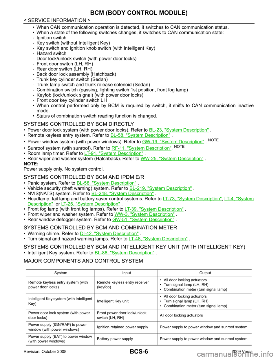
MAJOR COMPONENTS AND CONTROL SYSTEM
System Input Output
Remote keyless entry system (with
power door locks) Remote keyless entry receiver
(keyfob) • All door locking actuators
• Turn signal lamp (LH, RH)
• Combination meter (turn signal lamp)
Intelligent Key system (with Intelligent
Key) Intelligent Key unit• All door locking actuators
• Turn signal lamp (LH, RH)
• Combination meter (turn signal lamp)
Power door lock system (with power
door locks) Front power door lock/unlock
switch (LH, RH) All door locking actuators
Power supply (IGN/RAP) to power
window (with power windows) Ignition retained power supply Power supply to power window and sunroof system
Power supply (BAT) to power window
(with power windows) Battery power supply Power supply to power window and sunroof system
Page 449 of 4331

BCS
N
O P
CAN Communication System Description INFOID:0000000004306834
Refer to LAN-8, " System Description " .
Panic alarm
• Key switch
• Keyfob IPDM E/R
Vehicle security system • All door switches
• Keyfob
• Door lock/unlock switch
• Trunk key cylinder switch (Se-
dan)
• Front door key cylinder switch LH • IPDM/ER
• Security indicator lamp
Battery saver control • Ignition switch
• Combination switch IPDM E/R
Headlamp Combination switch IPDM E/R
Tail lamp Combination switch IPDM E/R
Front fog lamp (with front fog lamps) Combination switch IPDM E/R
Turn signal lamp Combination switch • Turn signal lamp
• Combination meter
Hazard lamp Hazard switch • Turn signal lamp
• Combination meter
Room lamp timer • Key switch
• Keyfob
• Main power window and door lock/unlock switch
• Front door switch LH
• All door switch Interior room lamp
Back door switch signal (Hatchback) Back door lock assembly Luggage room lamp
Back door lock signal (Hatchback) Back door lock assembly Back door opener
Trunk lamp switch signal (Sedan) Trunk lamp switch and trunk re-
lease solenoid Luggage room lamp
Trunk lid opener signal (Sedan) Trunk lamp switch and trunk re-
lease solenoid Trunk lid opener
Key warning chime • Key switch
• Front door switch LH Combination meter (warning buzzer)
Light warning chime • Combination switch
• Key switch
• Front door switch LH Combination meter (warning buzzer)
Seat belt warning chime • Seat belt buckle switch LH
• Ignition switch Combination meter (warning buzzer)
Front wiper and washer system • Combination switch
• Ignition switch IPDM E/R
Rear window defogger Rear window defogger switch IPDM E/R
Rear wiper and washer system
(Hatchback) • Combination switch
• Ignition switch Rear wiper motor
A/C switch signal Front air control ECM
Blower fan switch signal Front air control ECM
A/C indicator signal Front air control A/C indicator
Low tire pressure warning system Remote keyless entry receiver Combination meter System Input Output
Page 453 of 4331
BCS
N
O P
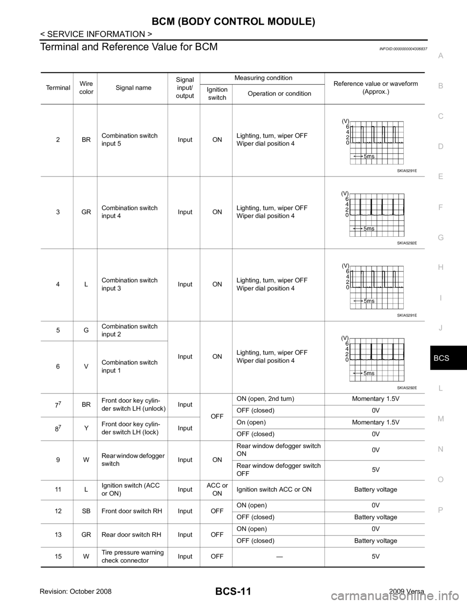
Terminal and Reference Value for BCM
INFOID:0000000004306837
Terminal Wire
color Signal name Signal
input/
output Measuring condition
Reference value or waveform
(Approx.)
Ignition
switch Operation or condition
2 BR Combination switch
input 5 Input ONLighting, turn, wiper OFF
Wiper dial position 4
3 GR Combination switch
input 4 Input ONLighting, turn, wiper OFF
Wiper dial position 4
4 L Combination switch
input 3 Input ONLighting, turn, wiper OFF
Wiper dial position 4
5 G Combination switch
input 2
Input ONLighting, turn, wiper OFF
Wiper dial position 4
6 V Combination switch
input 1
7 7
BRFront door key cylin-
der switch LH (unlock) Input
OFFON (open, 2nd turn) Momentary 1.5V
OFF (closed) 0V
8 7
YFront door key cylin-
der switch LH (lock) InputOn (open) Momentary 1.5V
OFF (closed) 0V
9 W Rear window defogger
switch Input ONRear window defogger switch
ON 0V
Rear window defogger switch
OFF 5V
11 L Ignition switch (ACC
or ON) InputACC or
ON Ignition switch ACC or ON Battery voltage
12 SB Front door switch RH Input OFF ON (open) 0V
OFF (closed) Battery voltage
13 GR Rear door switch RH Input OFF ON (open) 0V
OFF (closed) Battery voltage
15 W Tire pressure warning
check connector Input OFF — 5V
Page 455 of 4331
BCM (BODY CONTROL MODULE)
BCS-13
< SERVICE INFORMATION >
C
D E
F
G H
I
J
L
M A
B BCS
N
O P
30
1
VBack door/trunk out-
put Output —Back door open (switch
closed) 0V
Back door closed (switch
open) 5V
30 3
VBack door opener
switch Input —All doors locked (SW OFF) Battery voltage
All doors unlocked (SW ON) 0V
30 4
VTrunk lid opener
switch Input —All doors locked (SW OFF) Battery voltage
All doors unlocked (SW ON) 0V
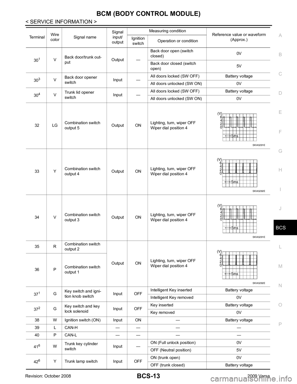
32 LG Combination switch
output 5 Output ONLighting, turn, wiper OFF
Wiper dial position 4
33 Y Combination switch
output 4 Output ON
Lighting, turn, wiper OFF
Wiper dial position 4
34 V Combination switch
output 3 Output ONLighting, turn, wiper OFF
Wiper dial position 4
35 R Combination switch
output 2
Output ONLighting, turn, wiper OFF
Wiper dial position 4
36 P Combination switch
output 1
37 1
GKey switch and igni-
tion knob switch Input OFFIntelligent Key inserted Battery voltage
Intelligent Key removed 0V
37 2
GKey switch and key
lock solenoid Input OFFKey inserted Battery voltage
Key removed 0V
38 W Ignition switch (ON) Input ON — Battery voltage
39 L CAN-H — — — —
40 P CAN-L — — — —
41 6
WTrunk key cylinder
switch Input —ON (Full unlock position) 0V
OFF (Neutral position) 5V
42 6
Y Trunk lamp switch Input OFF ON (trunk open) 0V
OFF (trunk closed) Battery voltage
Terminal
Wire
color Signal name Signal
input/
output Measuring condition
Reference value or waveform
(Approx.)
Ignition
switch Operation or condition SKIA5291E
SKIA5292E
SKIA5291E
SKIA5292E
Page 498 of 4331
POWER DOOR LOCK SYSTEM
BL-37
< SERVICE INFORMATION >
C
D E
F
G H
J
K L
M A
B BL
N
O P
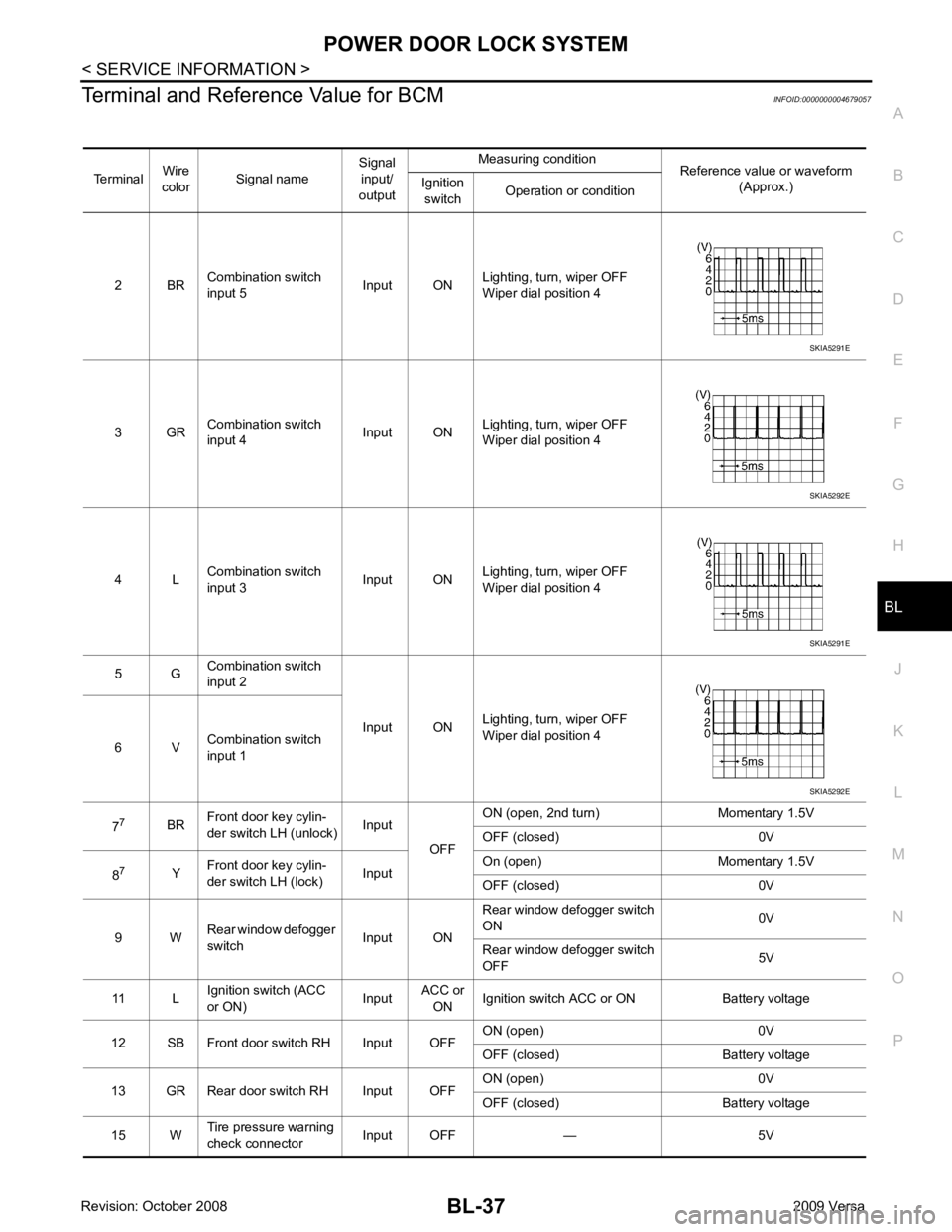
Terminal and Reference Value for BCM
INFOID:0000000004679057
Terminal Wire
color Signal name Signal
input/
output Measuring condition
Reference value or waveform
(Approx.)
Ignition
switch Operation or condition
2 BR Combination switch
input 5 Input ONLighting, turn, wiper OFF
Wiper dial position 4
3 GR Combination switch
input 4 Input ONLighting, turn, wiper OFF
Wiper dial position 4
4 L Combination switch
input 3 Input ONLighting, turn, wiper OFF
Wiper dial position 4
5 G Combination switch
input 2
Input ONLighting, turn, wiper OFF
Wiper dial position 4
6 V Combination switch
input 1
7 7
BRFront door key cylin-
der switch LH (unlock) Input
OFFON (open, 2nd turn) Momentary 1.5V
OFF (closed) 0V
8 7
YFront door key cylin-
der switch LH (lock) InputOn (open) Momentary 1.5V
OFF (closed) 0V
9 W Rear window defogger
switch Input ONRear window defogger switch
ON 0V
Rear window defogger switch
OFF 5V
11 L Ignition switch (ACC
or ON) InputACC or
ON Ignition switch ACC or ON Battery voltage
12 SB Front door switch RH Input OFF ON (open) 0V
OFF (closed) Battery voltage
13 GR Rear door switch RH Input OFF ON (open) 0V
OFF (closed) Battery voltage
15 W Tire pressure warning
check connector Input OFF — 5V SKIA5291E
SKIA5292E
SKIA5291E
SKIA5292E
Page 500 of 4331
POWER DOOR LOCK SYSTEM
BL-39
< SERVICE INFORMATION >
C
D E
F
G H
J
K L
M A
B BL
N
O P
30
1
VBack door/trunk out-
put Output —Back door open (switch
closed) 0V
Back door closed (switch
open) 5V
30 3
VBack door opener
switch Input —All doors locked (SW OFF) Battery voltage
All doors unlocked (SW ON) 0V
30 4
VTrunk lid opener
switch Input —All doors locked (SW OFF) Battery voltage
All doors unlocked (SW ON) 0V
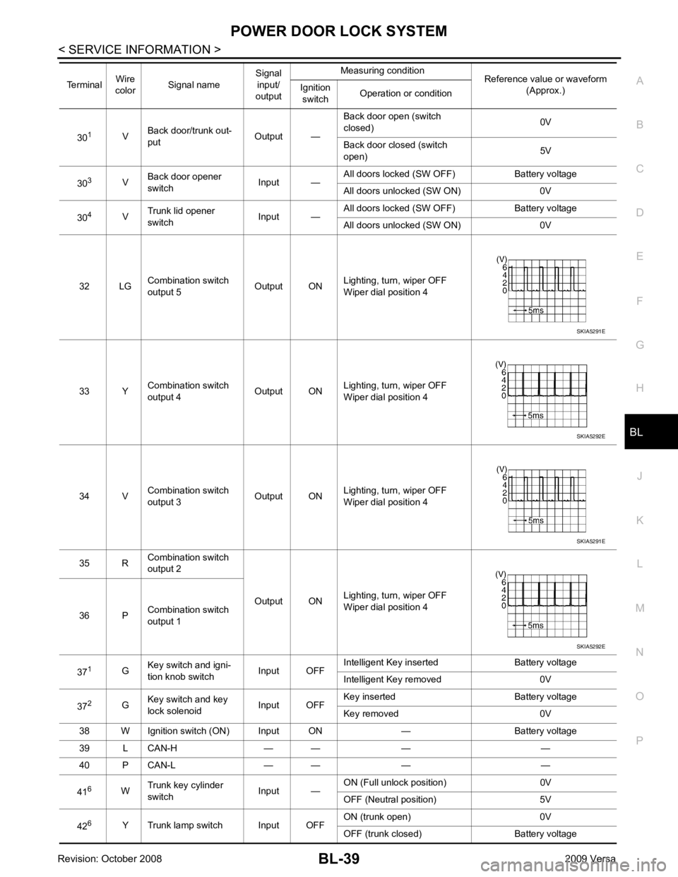
32 LG Combination switch
output 5 Output ONLighting, turn, wiper OFF
Wiper dial position 4
33 Y Combination switch
output 4 Output ON
Lighting, turn, wiper OFF
Wiper dial position 4
34 V Combination switch
output 3 Output ONLighting, turn, wiper OFF
Wiper dial position 4
35 R Combination switch
output 2
Output ONLighting, turn, wiper OFF
Wiper dial position 4
36 P Combination switch
output 1
37 1
GKey switch and igni-
tion knob switch Input OFFIntelligent Key inserted Battery voltage
Intelligent Key removed 0V
37 2
GKey switch and key
lock solenoid Input OFFKey inserted Battery voltage
Key removed 0V
38 W Ignition switch (ON) Input ON — Battery voltage
39 L CAN-H — — — —
40 P CAN-L — — — —
41 6
WTrunk key cylinder
switch Input —ON (Full unlock position) 0V
OFF (Neutral position) 5V
42 6
Y Trunk lamp switch Input OFF ON (trunk open) 0V
OFF (trunk closed) Battery voltage
Terminal
Wire
color Signal name Signal
input/
output Measuring condition
Reference value or waveform
(Approx.)
Ignition
switch Operation or condition SKIA5291E
SKIA5292E
SKIA5291E
SKIA5292E
Page 501 of 4331

BL-40< SERVICE INFORMATION >
POWER DOOR LOCK SYSTEM
43 5
R Back door switch Input OFF ON (open) 0V
OFF (closed) Ba ttery voltage
44 5
LG Rear wiper auto stop Input ON Rear wiper operating 0
Rear wiper stopped Battery
45 7
GR Lock switch Input OFF ON (lock) 0V
OFF Battery voltage
46 7
L Unlock switch Input OFF ON (unlock) 0V
OFF Battery voltage
47 BR Front door switch LH Input OFF ON (open) 0V
OFF (closed) Ba ttery voltage
48 O Rear door switch LH Input OFF ON (open) 0V
OFF (closed) Ba ttery voltage
49 P Luggage room lamp Output OFF Any door open (ON) 0V
All doors closed (OFF) Battery voltage
50 SB A/C indicator Output ON A/C OFF 0
A/C ON Battery voltage
53 5
RBack door lock assem-
bly (actuator) Output OFF Back door (open) Battery voltage
53 6
RTrunk lamp switch and
trunk release solenoid Output OFF Trunk lid (open) Battery voltage
55 5
VRear wiper motor out-
put Output ONOFF 0
ON Battery voltage
56 R Battery saver output Output OFF
30 minutes after ignition
switch is turned OFF 0V
ON — Battery voltage
57 LG Battery power supply Input OFF — Battery voltage
59 7
GFront door lock actua-
tor LH (unlock) Output OFFOFF (neutral) 0V
ON (unlock) Battery voltage
60 V Turn signal (left) Output ON Turn left ON
61 W Turn signal (right) Output ON Turn right ON
63 BR Interior room lamp Output OFF Any door
switch ON (open) 0V
OFF (closed) Battery voltage
Terminal
Wire
color Signal name Signal
input/
output Measuring condition
Reference value or waveform
(Approx.)
Ignition
switch Operation or condition SKIA3009J
SKIA3009J