2009 NISSAN TIIDA e control
[x] Cancel search: e controlPage 4261 of 4331
![NISSAN TIIDA 2009 Service Repair Manual TROUBLE DIAGNOSIS FOR SYMPTOMS
STC-21
< SERVICE INFORMATION >
[EPS] C
D E
F
H I
J
K L
M A
B STC
N
O
P
TROUBLE DIAGNOSIS FOR SYMPTOMS
EPS Warning Lamp Does Not Turn ON INFOID:0000000004307307
SYMPTOM: NISSAN TIIDA 2009 Service Repair Manual TROUBLE DIAGNOSIS FOR SYMPTOMS
STC-21
< SERVICE INFORMATION >
[EPS] C
D E
F
H I
J
K L
M A
B STC
N
O
P
TROUBLE DIAGNOSIS FOR SYMPTOMS
EPS Warning Lamp Does Not Turn ON INFOID:0000000004307307
SYMPTOM:](/manual-img/5/57398/w960_57398-4260.png)
TROUBLE DIAGNOSIS FOR SYMPTOMS
STC-21
< SERVICE INFORMATION >
[EPS] C
D E
F
H I
J
K L
M A
B STC
N
O
P
TROUBLE DIAGNOSIS FOR SYMPTOMS
EPS Warning Lamp Does Not Turn ON INFOID:0000000004307307
SYMPTOM: EPS warning lamp does not turn ON when ignition switch to “ON”.
DIAGNOSTIC PROCEDURE 1.
CHECK SYSTEM FOR CAN COMMUNICATION LINE
Perform self-diagnosis. Refer to STC-11, " CONSULT-III Function (EPS) " .
Is the “ CAN COMM CIRCUIT [U1000] ” displayed?
YES >> Perform trouble diagnosis for CAN communication line. Refer to
STC-19, " DTC U1000 CAN
COMM CIRCUIT " .
NO >> GO TO 2. 2.
CHECK EPS CONTROL UNIT
Check EPS control unit input/output signal. Refer to STC-9, " EPS Control Unit Input/Output Signal Reference
Value " .
OK or NG OK >> GO TO 3.
NG >> Check EPS control unit pin terminals for damage or loose connection with harness connector. If
any items are damaged, repair or replace damaged parts. 3.
SYMPTOM CHECK
Check again.
OK or NG OK >>
INSPECTION END
NG >> Replace combination meter. Refer to DI-19, " Removal and Installation " .
EPS Warning Lamp Does Not Turn OFF INFOID:0000000004307308
SYMPTOM: EPS warning lamp does not turn OFF for several seconds after starting the engine.
DIAGNOSTIC PROCEDURE 1.
CHECK SELF-DIAGNOSTIC RESULTS
Perform self-diagnosis. Refer to STC-11, " CONSULT-III Function (EPS) " .
Is any malfunction detected by self-diagnosis? YES >> Check the malfunctioning system.
NO >> GO TO 2. 2.
CHECK EPS CONTROL UNI T POWER SUPPLY CIRCUIT
1. Turn ignition switch “OFF”.
2. Disconnect EPS control unit harness connector.
3. Turn ignition switch “ON”. (Do not start engine.)
4. Check voltage between EPS control unit harness connector (A) terminals and ground.
Connector Terminal VoltageM53 10 – Ground Battery voltage
M54 17 – Ground Battery voltage SGIA1626E
Page 4262 of 4331
![NISSAN TIIDA 2009 Service Repair Manual STC-22< SERVICE INFORMATION >
[EPS]
TROUBLE DIAGNOSIS FOR SYMPTOMS
5. Turn ignition switch “OFF”.
6. Check voltage between EPS control unit harness connector (A) terminals and ground.
7. Connect E NISSAN TIIDA 2009 Service Repair Manual STC-22< SERVICE INFORMATION >
[EPS]
TROUBLE DIAGNOSIS FOR SYMPTOMS
5. Turn ignition switch “OFF”.
6. Check voltage between EPS control unit harness connector (A) terminals and ground.
7. Connect E](/manual-img/5/57398/w960_57398-4261.png)
STC-22< SERVICE INFORMATION >
[EPS]
TROUBLE DIAGNOSIS FOR SYMPTOMS
5. Turn ignition switch “OFF”.
6. Check voltage between EPS control unit harness connector (A) terminals and ground.
7. Connect EPS control unit harness connector.
OK or NG OK >> GO TO 3.
NG >> Check the following. If any items are damaged, repair or replace damaged parts.
• 60 A fusible link (No. m, located in the fuse and fusible link block). Refer to PG-3 .
• 10 A fuse [No. 2, located in the fuse block (J/B)]. Refer to PG-3 .
• Harness for short or open between battery and EPS control unit harness connector M54 termi-
nal 17.
• Harness for short or open between ignition switch and EPS control unit harness connector M53 terminal 10. 3.
CHECK EPS CONTROL UNIT GROUND CIRCUIT
1. Turn ignition switch “OFF”.
2. Disconnect EPS control unit harness connector.
3. Check continuity between EP S control unit harness connector
(A) terminal and ground.
Also check harness for short to power.
4. Connect EPS control unit harness connector.
OK or NG OK >> GO TO 4.
NG >> Repair open circuit or short to ground or short to power in harness or connectors. 4.
CHECK EPS CONTROL UNIT
Check EPS control unit input/output signal. Refer to STC-9, " EPS Control Unit Input/Output Signal Reference
Value " .
OK or NG OK >> GO TO 5.
NG >> Check EPS control unit pin terminals for dam age or loose connection with harness connector. If
any items are damaged, repair or replace damaged parts. 5.
SYMPTOM CHECK
Check again.
OK or NG OK >>
INSPECTION END
NG >> Replace combination meter. Refer to DI-19, " Removal and Installation " .
Steering Wheel Turning Fo rce Is Heavy or Light INFOID:0000000004307309
SYMPTOM:
Steering wheel turning force is heavy or light, while driving.
DIAGNOSTIC PROCEDURE 1.
CHECK SYSTEM FOR CAN COMMUNICATION LINE
Perform self-diagnosis. Refer to STC-11, " CONSULT-III F
unction (EPS) " .
Connector Terminal Voltage
M53 10 – Ground Approx. 0 V
M54 17 – Ground Battery voltage SGIA1627E
Connector Terminal Continuity
M54 18 YES SGIA1628E
Page 4263 of 4331
![NISSAN TIIDA 2009 Service Repair Manual STC
N
O P
Is the “ CAN COMM CIRCUIT [U1000] ” displayed?
YES >> Perform trouble diagnosis for CAN communication line. Refer to
STC-19, " DTC U1000 CAN
COMM CIRCUIT " .
NO-1 >> With NISSAN TIIDA 2009 Service Repair Manual STC
N
O P
Is the “ CAN COMM CIRCUIT [U1000] ” displayed?
YES >> Perform trouble diagnosis for CAN communication line. Refer to
STC-19, " DTC U1000 CAN
COMM CIRCUIT " .
NO-1 >> With](/manual-img/5/57398/w960_57398-4262.png)
STC
N
O P
Is the “ CAN COMM CIRCUIT [U1000] ” displayed?
YES >> Perform trouble diagnosis for CAN communication line. Refer to
STC-19, " DTC U1000 CAN
COMM CIRCUIT " .
NO-1 >> With ABS: GO TO 2.
NO-2 >> Without ABS: GO TO 3. CONSULT-III
Function (ABS) " .
Is any malfunction detected by self-diagnosis? YES >> Check the malfunctioning system.
NO >> GO TO 4. CONSULT-III Function (TRANSMISSION) " .
Is any malfunction detected by self-diagnosis? YES >> Check the malfunctioning system.
NO >> GO TO 4. CONSULT-III Function (METER/M&A) " .
Is any malfunction detected by self-diagnosis? YES >> Check the malfunctioning system.
NO >> GO TO 5. CONSULT-III Function (ENGINE) " (MR TYPE 1),
EC-1116," CONSULT-III Function (ENGINE) " (MR TYPE 2) or
EC-103, " CONSULT-III Function " (HR16DE).
Is any malfunction detected by self-diagnosis? YES >> Check the malfunctioning system.
NO >> GO TO 6. DTC C1606 EPS MOTOR " .
OK or NG OK >> GO TO 7.
NG >> Repair or replace damaged parts. EPS Control Unit Input/Output Signal Reference
Value " .
OK or NG OK >> GO TO 8.
NG >> Check EPS control unit pin terminals for damage or loose connection with harness connector. If
any items are damaged, repair or replace damaged parts. OK >>
INSPECTION END
NG >> Check the steering wheel turning force because there may be mechanical malfunction. Refer to PS-6, " On-Vehicle Inspection and Service " .
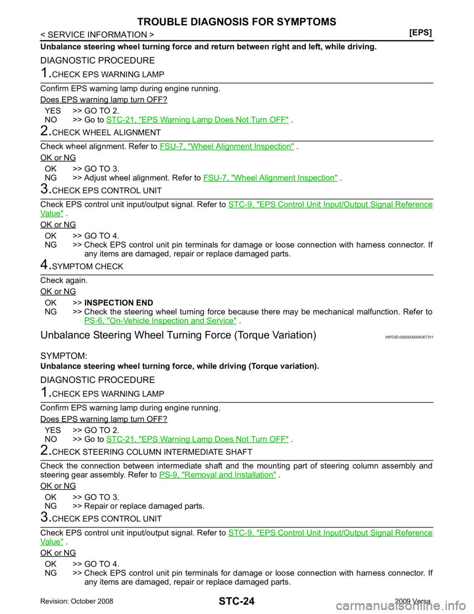
Unbalance Steering Wheel Turning Forc e and Return Between Right and Left
INFOID:0000000004307310
SYMPTOM:
Page 4264 of 4331

YES >> GO TO 2.
NO >> Go to STC-21, " EPS Warning Lamp Does Not Turn OFF " .
Wheel Alignment Inspection " .
OK or NG OK >> GO TO 3.
NG >> Adjust wheel alignment. Refer to FSU-7, " Wheel Alignment Inspection " .
EPS Control Unit Input/Output Signal Reference
Value " .
OK or NG OK >> GO TO 4.
NG >> Check EPS control unit pin terminals for dam age or loose connection with harness connector. If
any items are damaged, repair or replace damaged parts. OK >>
INSPECTION END
NG >> Check the steering wheel turning force because there may be mechanical malfunction. Refer to
PS-6, " On-Vehicle Inspection and Service " .
Unbalance Steering Wheel Turn ing Force (Torque Variation) INFOID:0000000004307311
SYMPTOM:
Unbalance steering wheel turning for ce, while driving (Torque variation).
DIAGNOSTIC PROCEDURE YES >> GO TO 2.
NO >> Go to STC-21, " EPS Warning Lamp Does Not Turn OFF " .
Removal and Installation " .
OK or NG OK >> GO TO 3.
NG >> Repair or replace damaged parts. EPS Control Unit Input/Output Signal Reference
Value " .
OK or NG OK >> GO TO 4.
NG >> Check EPS control unit pin terminals for dam age or loose connection with harness connector. If
any items are damaged, repair or replace damaged parts.
Page 4268 of 4331

WT
N
O P
5. When the repair work is completed, return the ignition switch to the
″LOCK ″ position before connecting
the battery cables. (At this time, the steering lock mechanism will engage.)
6. Perform a self-diagnosis check of al l control units using CONSULT-III.
Page 4281 of 4331

OK >> GO TO 4.
NG >> Repair or replace damaged parts. OK >> Carry out self-diagnosis.
NG >> Replace battery in transmitter activation tool.
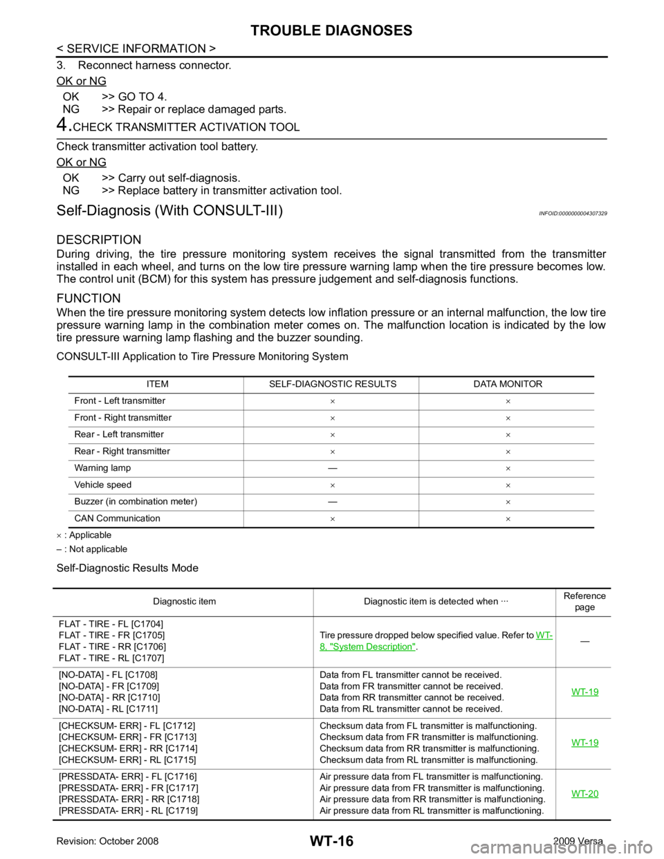
Self-Diagnosis (With CONSULT-III) INFOID:0000000004307329
DESCRIPTION
During driving, the tire pressure monitoring system receives the signal transmitted from the transmitter
installed in each wheel, and turns on the low tire pressure warning lamp when the tire pressure becomes low.
The control unit (BCM) for this system has pressure judgement and self-diagnosis functions.
FUNCTION
When the tire pressure monitoring syst em detects low inflation pressure or an internal malfunction, the low tire
pressure warning lamp in the combination meter comes on. The malfunction location is indicated by the low
tire pressure warning lamp flashing and the buzzer sounding.
CONSULT-III Application to Tire Pressure Monitoring System
× : Applicable
– : Not applicable
Self-Diagnostic Results Mode ITEM SELF-DIAGNOSTIC RESULTS DATA MONITOR
Front - Left transmitter × ×
Front - Right transmitter × ×
Rear - Left transmitter × ×
Rear - Right transmitter × ×
Warning lamp — ×
Vehicle speed × ×
Buzzer (in combination meter) — ×
CAN Communication × × 8, " System Description " .
Page 4295 of 4331

WW
N
O P
FRONT WIPER AND WASHER SYSTEM
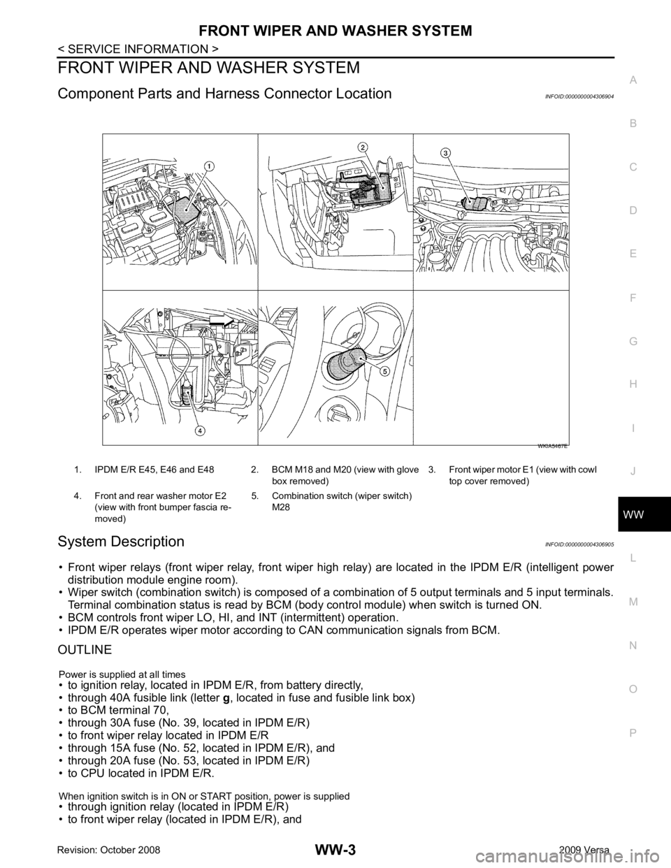
Component Parts and Har ness Connector Location INFOID:0000000004306904
System Description INFOID:0000000004306905
• Front wiper relays (front wiper relay, front wiper hi gh relay) are located in the IPDM E/R (intelligent power
distribution module engine room).
• Wiper switch (combination switch) is composed of a combination of 5 output terminals and 5 input terminals.
Terminal combination status is read by BCM (body control module) when switch is turned ON.
• BCM controls front wiper LO, HI, and INT (intermittent) operation.
• IPDM E/R operates wiper motor accordi ng to CAN communication signals from BCM.
OUTLINE
Power is supplied at all times
• to ignition relay, located in IPDM E/R, from battery directly,
• through 40A fusible link (letter g, located in fuse and fusible link box)
• to BCM terminal 70,
• through 30A fuse (No. 39, located in IPDM E/R)
• to front wiper relay located in IPDM E/R
• through 15A fuse (No. 52, located in IPDM E/R), and
• through 20A fuse (No. 53, located in IPDM E/R)
• to CPU located in IPDM E/R.
When ignition switch is in ON or START position, power is supplied
• through ignition relay (located in IPDM E/R)
• to front wiper relay (located in IPDM E/R), and 1. IPDM E/R E45, E46 and E48 2. BCM M18 and M20 (view with glove
box removed)3. Front wiper motor E1
(view with cowl
top cover removed)
4. Front and rear washer motor E2 (view with front bumper fascia re-
moved) 5. Combination switch (wiper switch)
M28
Page 4302 of 4331

Terminal and Reference Value for BCM " .
Terminal and Reference Value for IPDM E/R INFOID:0000000004306910
Refer to PG-24, " Terminal and Reference Value for IPDM E/R " .
How to Proceed with Trouble Diagnosis INFOID:0000000004306911
1. Confirm symptoms and customer complaint.
2. Understand operation description and function description. Refer to WW-3, " System Description " .
3. Perform preliminary check. Refer to WW-10, " Preliminary Check " .
4. Check symptom and repair or replace malfunctioning parts.
5. Does front wiper and washer operate normally ? If YES, GO TO 6. If NO, GO TO 4.
6. Inspection End.
Preliminary Check INFOID:0000000004306912
CHECK POWER SUPPLY AND GROUND CIRCUIT FOR BCM
Refer to BCS-15, " BCM Power Supply and Ground Circuit Inspection "
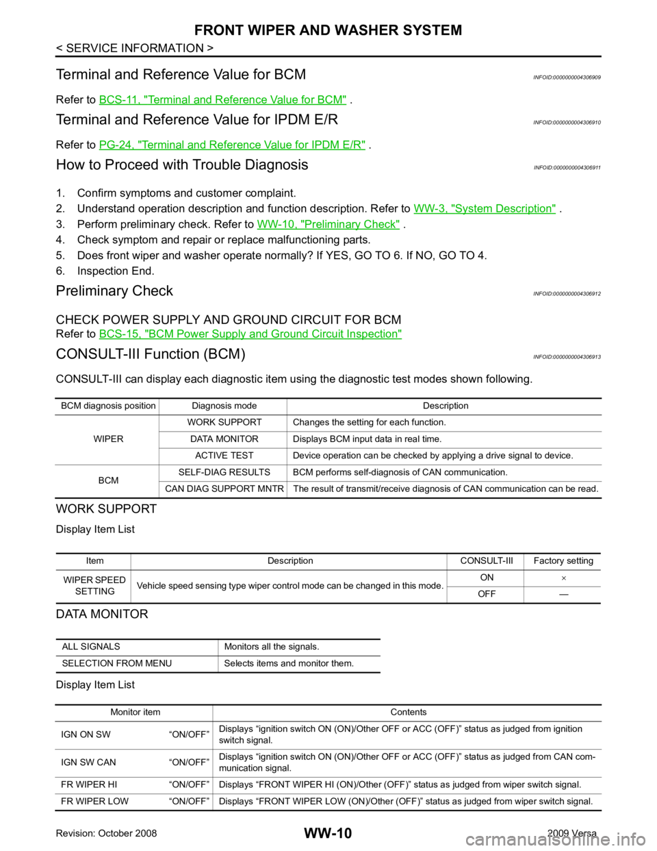
Item Description CONSULT-III Factory setting
WIPER SPEED SETTING Vehicle speed sensing type wiper control mode can be changed in this mode. ON
×
OFF — ALL SIGNALS Monitors all the signals.
SELECTION FROM MENU Selects items and monitor them. Monitor item Contents
IGN ON SW “ON/OFF” Displays “ignition switch ON (ON)/Other OFF or ACC (OFF)” status as judged from ignition
switch signal.
IGN SW CAN “ON/OFF” Displays “ignition switch ON (ON)/Other OFF or ACC (OFF)” status as judged from CAN com-
munication signal.
FR WIPER HI “ON/OFF” Displays “FRONT WI PER HI (ON)/Other (OFF)” status as judged from wiper switch signal.
FR WIPER LOW “ON/OFF” Displays “FRONT WIPER LOW (ON)/Other (OFF)” status as judged from wiper switch signal.