Page 3926 of 4331
MTC
N
O P
1. Turn ignition switch OFF.
2. Disconnect front air control connector and BCM connector.
3. Check continuity between BCM harness connector M18 (A) ter-
minal 28 and front air control harness connector M33 (B) termi-
nal 14.
OK or NG OK >> GO TO 12.
NG >> Repair harness or connector. OK >> GO TO 13.
NG >> Replace front air control. Refer to MTC-56, " Disassem-
bly and Assembly " .
OK >> GO TO 14.
NG >> Repair harness or connector.
Page 3927 of 4331
OK >> GO TO 15.
NG >> GO TO 17. OK >> GO TO 16.
NG >> Replace front air control. Refer to MTC-56, " Disassem-
bly and Assembly " .
OK >> GO TO 17.
NG >> Repair harness or connector. SJIA0760E
Page 3928 of 4331
MTC
N
O P
OK or NG OK >> • GO TO 18 (with CVT).
• GO TO 19 (without CVT).
NG >> GO TO 21. OK >> Repair thermo control amp. jumper as necessary.
NG >> Repair harness or connector. OK >> GO TO 20.
NG >> Check power supply circuit and 10A fuse [No. 16, located in the fuse block (JB)]. Refer to PG-72 .
• If fuse is OK, check harness for open circuit. Repair or
replace if necessary.
• If fuse is NG, replace fuse and check harness for short circuit. Repair or replace if necessary. OK >> Replace thermo control amp. Refer to
MTC-57," Removal and Installation " .
NG >> Repair harness or connector.
Page 3934 of 4331

MTC
N
O P
Testing must be performed as follows:
TEST READING Recirculating-to-discharge Air Temperature Table
Ambient Air Temperature-to-operating Pressure Table
*1: With blower control dial in the "1" position
*2: With blower control dial in the "4" position.
TROUBLE DIAGNOSIS FOR ABNORMAL PRESSURE Whenever system’s high and/or low side pressure(s) is /are abnormal, diagnose using a manifold gauge. The
marker above the gauge scale in the following tables indicates the standard (usual) pressure range. Since the
standard (usual) pressure, however, differs from vehicle to vehicle, refer to above table (Ambient air tempera-
ture-to-operating pressure table). Vehicle condition Indoors or in the shade (in a well-ventilated place)
Doors Closed
Door window Open
Hood Open
TEMP. Max. COLD
Mode control dial (Ventilation) set
Intake door lever (Recirculation) set
Blower speed Max. speed set
Engine speed Idle speed
Operate the air conditioning system for 10 minutes before taking measurements. Inside air (Recirculating air) at blower assembly inlet
Discharge air temperature at center ventilator
°C ( °F)
Relative humidity
% Air temperature
°C ( °F)
50 - 60 20 (68) 7.2 - 9.1 (45 - 48)
25 (77) 11.4 - 13.8 (53 - 57)
30 (86) 15.5 - 18.4 (60 - 65)
35 (95) 20.3 - 23.7 (69 - 75)
60 - 70 20 (68) 9.1 - 10.9 (48 - 52)
25 (77) 13.8 - 16.2 (57 - 61)
30 (86) 18.4 - 21.3 (65 - 70)
35 (95) 23.7 - 27.1 (75 - 81) Ambient air
High-pressure (Discharge side)
kPa (bar, kg/cm 2
, psi) Low-pressure (Suction side)
kPa (bar, kg/cm 2
, psi)
Relative humidity
% Air temperature
°C ( °F)
50 - 70 20 (68)
843 - 1,036 *1
(11.08 - 13.63, 8.6 - 10.6, 122 - 150) 159.0 - 194.0
(1.59 - 1.94, 1.62 - 1.98, 23.1 - 28.1)
25 (77) 1,094 - 1,338 *1
(10.94 - 13.38, 11.2 - 13.6, 159 - 194) 196.3 - 240.0
(1.96 - 2.40, 2.00 - 2.45, 28.5 - 34.8)
30 (86) 1,298 - 1,590 *1
(12.98 - 15.90, 13.2 - 16.2, 188 - 231) 248.0 - 302.7
(2.48 - 3.03, 2.53 - 3.09, 36.0 - 43.9)
35 (95) 1,383 - 1,688 *2
(13.83 - 16.88, 14.1 - 17.2, 201 - 245) 308.8 - 377.4
(3.09 - 3.77, 3.15 - 3.85, 44.8 - 54.7)
40 (104) 1,628 - 1,988 *2
(16.28 - 19.88, 16.6 - 20.3, 236 - 288) 377.4 - 461.2
(3.77 - 4.61, 3.85 - 4.70, 54.7 - 66.8)
Page 3936 of 4331

MTC
N
O P
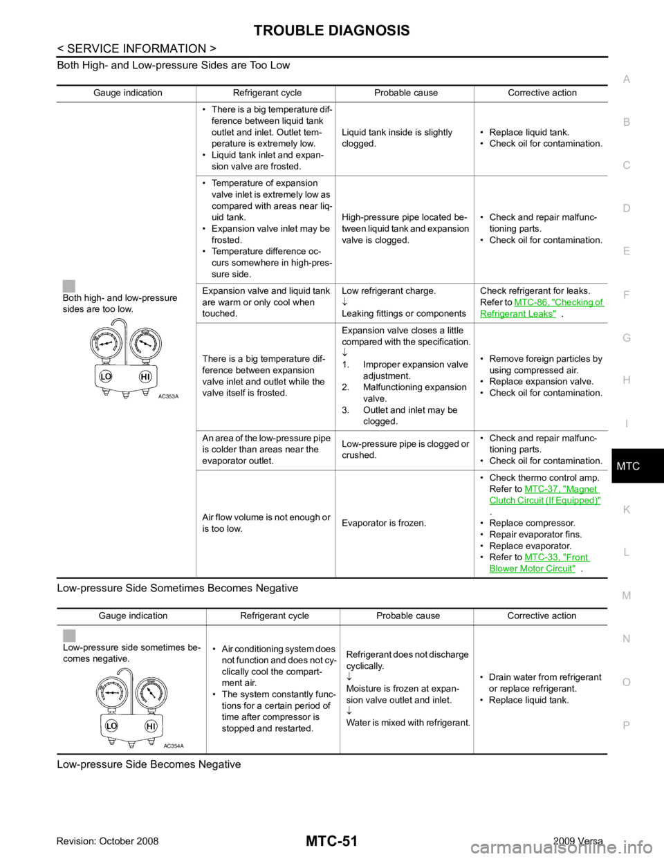
Both High- and Low-pressure Sides are Too Low
Low-pressure Side Some times Becomes Negative
Low-pressure Side Becomes Negative Gauge indication Refrigerant cycle Probable cause Corrective action
Both high- and low-pressure
sides are too low. • There is a big temperature dif-
ference between liquid tank
outlet and inlet. Outlet tem-
perature is extremely low.
• Liquid tank inlet and expan- sion valve are frosted. Liquid tank inside is slightly
clogged. • Replace liquid tank.
• Check oil for contamination.
• Temperature of expansion valve inlet is extremely low as
compared with areas near liq-
uid tank.
• Expansion valve inlet may be
frosted.
• Temperature difference oc- curs somewhere in high-pres-
sure side. High-pressure pipe located be-
tween liquid tank and expansion
valve is clogged. • Check and repair malfunc-
tioning parts.
• Check oil for contamination.
Expansion valve and liquid tank
are warm or only cool when
touched. Low refrigerant charge.
↓
Leaking fittings or components Check refrigerant for leaks.
Refer to MTC-86, " Checking of
Refrigerant Leaks " .
There is a big temperature dif-
ference between expansion
valve inlet and outlet while the
valve itself is frosted. Expansion valve closes a little
compared with the specification.
↓
1. Improper expansion valve
adjustment.
2. Malfunctioning expansion valve.
3. Outlet and inlet may be clogged. • Remove foreign particles by
using compressed air.
• Replace expansion valve.
• Check oil for contamination.
An area of the low-pressure pipe
is colder than areas near the
evaporator outlet. Low-pressure pipe is clogged or
crushed. • Check and repair malfunc-
tioning parts.
• Check oil for contamination.
Air flow volume is not enough or
is too low. Evaporator is frozen.• Check thermo control amp.
Refer to MTC-37, " Magnet
Clutch Circuit (If Equipped) "
.
• Replace compressor.
• Repair evaporator fins.
• Replace evaporator.
• Refer to MTC-33, " Front
Blower Motor Circuit " .
Page 3940 of 4331
MTC
N
O P
CONTROLLER
Removal and Installation INFOID:0000000004307076
REMOVAL 1. Remove cluster lid C and instrument finisher D. Refer to IP-11, " Component Parts " .
2. Remove intake door lever knob. Refer to MTC-56, " Disassembly and Assembly " .
3. Remove mounting screws and clips, and then remove controller finisher.
4. Remove mounting screws, and then pull out controller.
5. Remove instrument panel and pad. Refer to IP-11, " Component Parts " .
6. Remove air mix door cable, mode door cable and intake door cable from A/C unit assembly.
7. Disconnect connector, and then remove controller.
INSTALLATION Installation is in the reverse order of removal.
CAUTION:
Adjust the door cables during installation. Refer to MTC-63, " Intake Door Cable Adjustment " ,
MTC-65, " Mode Door Cable Adjustment " and
MTC-64, " Air Mix Door Cable Adjustment " .
Page 3942 of 4331
MTC
N
O P
THERMO CONTROL AMPLIFIER
Removal and Installation INFOID:0000000004307078
NOTE:
Only MR18DE - TYPE 2 systems are equipped with a thermo control amplifier.
REMOVAL 1. Remove evaporator. Refer to MTC-85, " Removal and Installation of Evaporator " .
CAUTION:
Cap or wrap the joint of the pipe with suitable ma terial such as vinyl tape to avoid the entry of air.
2. Mark the mounting position of the thermo control amp. and then remove thermo control amp. (1) from evaporator (2).
INSTALLATION Installation is in the reverse order of removal.
CAUTION:
• Replace O-rings for A/C piping with new on es, and apply compressor oil when installing.
• Install the thermo control amp. at the mark made during removal of the thermo control amp.
• When recharging refrigerant, check for leaks.
Page 3944 of 4331

MTC
N
O P
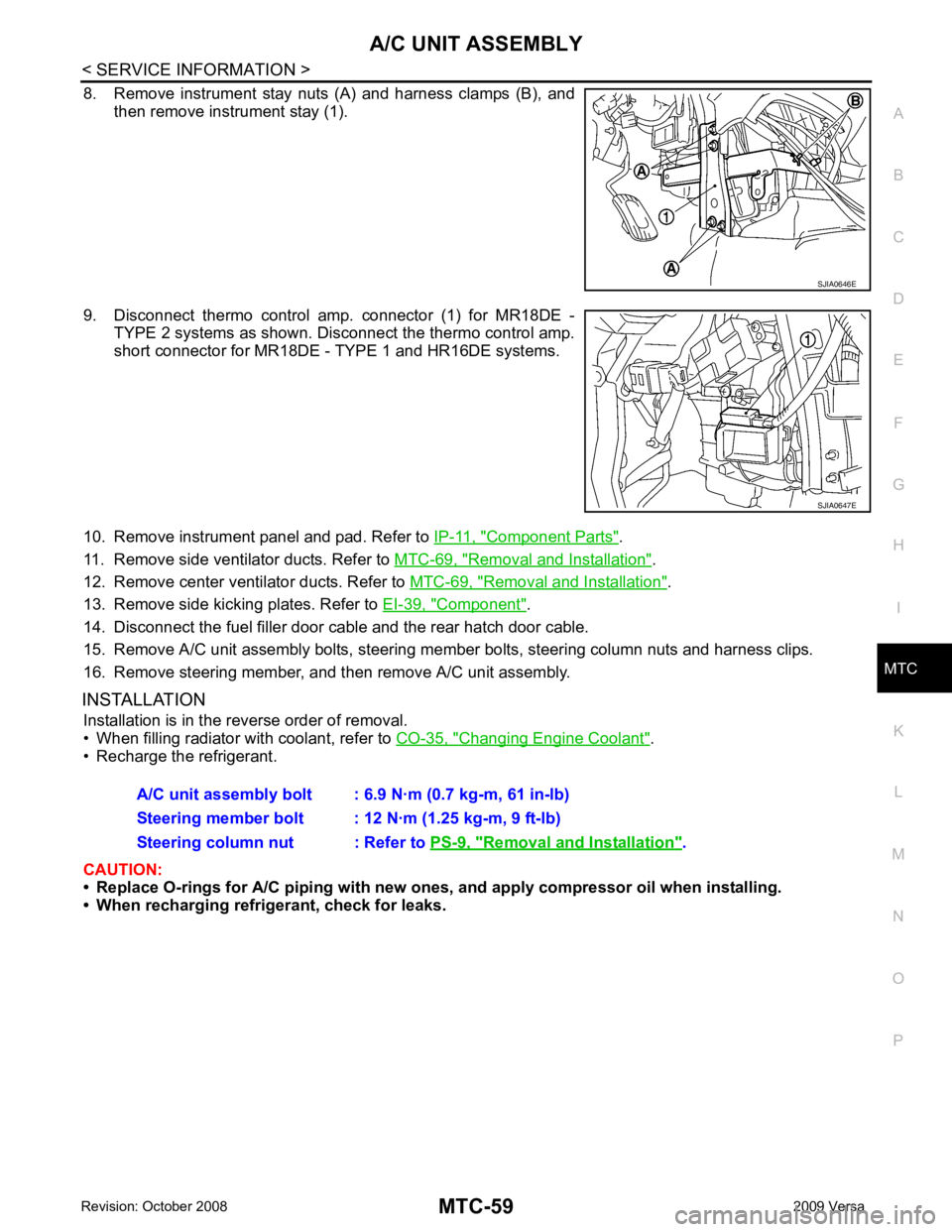
8. Remove instrument stay nuts (A) and harness clamps (B), and
then remove instrument stay (1).
9. Disconnect thermo control amp. connector (1) for MR18DE - TYPE 2 systems as shown. Disconnect the thermo control amp.
short connector for MR18DE - TYPE 1 and HR16DE systems.
10. Remove instrument panel and pad. Refer to IP-11, " Component Parts " .
11. Remove side ventilator ducts. Refer to MTC-69, " Removal and Installation " .
12. Remove center ventilator ducts. Refer to MTC-69, " Removal and Installation " .
13. Remove side kicking plates. Refer to EI-39, " Component " .
14. Disconnect the fuel filler door cable and the rear hatch door cable.
15. Remove A/C unit assembly bolts, steering member bolts, steering column nuts and harness clips.
16. Remove steering member, and then remove A/C unit assembly.
INSTALLATION Installation is in the reverse order of removal.
• When filling radiator with coolant, refer to CO-35, " Changing Engine Coolant " .
• Recharge the refrigerant.
CAUTION:
• Replace O-rings for A/C piping with new on es, and apply compressor oil when installing.
• When recharging refrigerant, check for leaks. Removal and Installation " .