Page 3900 of 4331
MTC
N
O P
REFRIGERATION SYSTEM
Refrigerant Cycle INFOID:0000000004307053
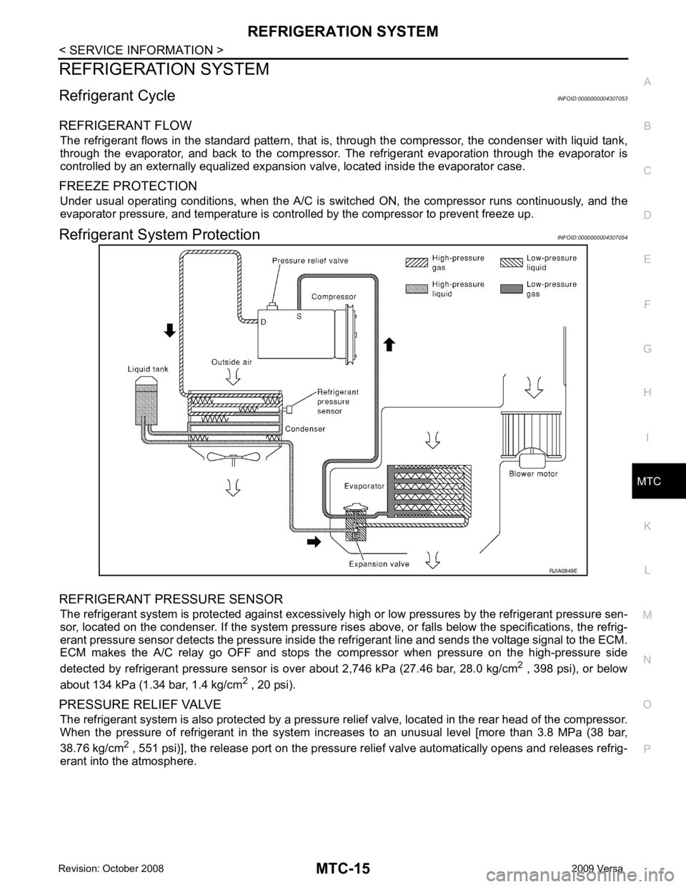
REFRIGERANT FLOW The refrigerant flows in the standard pattern, that is , through the compressor, the condenser with liquid tank,
through the evaporator, and back to the compressor. T he refrigerant evaporation through the evaporator is
controlled by an externally equalized expansion valve, located inside the evaporator case.
FREEZE PROTECTION Under usual operating conditions, when the A/C is s witched ON, the compressor runs continuously, and the
evaporator pressure, and temperature is controlled by the compressor to prevent freeze up.
Refrigerant System Protection INFOID:0000000004307054
REFRIGERANT PRESSURE SENSOR The refrigerant system is protected against excessively hi gh or low pressures by the refrigerant pressure sen-
sor, located on the condenser. If the system pressure rise s above, or falls below the specifications, the refrig-
erant pressure sensor detects the pressure inside t he refrigerant line and sends the voltage signal to the ECM.
ECM makes the A/C relay go OFF and stops the compressor when pressure on the high-pressure side
detected by refrigerant pressure sensor is over about 2,746 kPa (27.46 bar, 28.0 kg/cm 2
, 398 psi), or below
about 134 kPa (1.34 bar, 1.4 kg/cm 2
, 20 psi).
PRESSURE RELIEF VALVE The refrigerant system is also protected by a pressure relief valve, located in the rear head of the compressor.
When the pressure of refrigerant in the system in creases to an unusual level [more than 3.8 MPa (38 bar,
38.76 kg/cm 2
, 551 psi)], the release port on the pressure relief valve automatically opens and releases refrig-
erant into the atmosphere.
Page 3904 of 4331
MTC
N
O P
AIR CONDITIONER CONTROL
Control Operation INFOID:0000000004307057
BLOWER CONTROL DIAL This dial turns the fan ON and OFF, and controls fan speed.
TEMPERATURE CONTROL DIAL This dial allows you to adjust the temperature of the discharge air.
MODE DOOR CONTROL DIAL This dial controls the outlet air flow.
INTAKE DOOR LEVER • Recirculation (REC) position: Interior air is recirculated inside the vehicle.
• Fresh (FRE) position: Outside air is drawn into the passenger compartment.
REAR WINDOW DEFOGGER SWITCH When illumination is ON, rear window is defogged.
A/C SWITCH (IF EQUIPPED) The A/C switch controls the air conditioner system. When the switch is depressed with the fan ON, the com-
pressor will turn ON. The indicator lamp also illuminates. 1. Intake door lever 2. Mode door control dial 3. Rear window defogger switch
4. Blower control dial 5. A/C switch (if equipped) 6. Temperature control dial
Page 3916 of 4331
MTC
N
O P
1. Turn blower control dial clockwise to "1" position. Blower should operate on low speed.
2. Turn blower control dial clockwise to "2" position, and continue checking blower speed until all speeds are
checked.
3. Leave blower on Maximum speed.
If NG, go to trouble diagnosis procedure for MTC-33, " Front Blower Motor Circuit " .
If OK, continue the check.
CHECKING DISCHARGE AIR 1. Turn mode door control dial to each position.
2. Confirm that discharge air comes out accord ing to the air distribution table. Refer to MTC-20, " Discharge
Air Flow " .
If NG, go to trouble diagnosis procedure for MTC-31, " Mode Door " .
If OK, continue the check.
CHECKING RECIRCULATION 1. Set intake door lever to REC position.
2. Operate intake door lever to FRE position.
3. Listen for intake door position change (you should hear blower sound change slightly).
If NG, go to trouble diagnosis procedure for MTC-33, " Intake Door " .
If OK, continue the check.
CHECKING TEMPERATURE DECREASE 1. Turn temperature control dial counterclockwise to full cold position.
2. Check for cold air at discharge air outlets.
If NG, go to trouble diagnosis procedure for MTC-45, " Insufficient Cooling " .
If OK, continue the check.
CHECKING TEMPERATURE INCREASE 1. Turn temperature control dial clockwise to full hot position.
2. Check for hot air at discharge air outlets.
If NG, go to trouble diagnosis procedure for MTC-52, " Insufficient Heating " .
If OK, continue the check.
CHECKING A/C SWITCH (IF EQUIPPED) 1. Turn fan control dial to the desired (1 to 4 speed) position.
2. Press A/C switch.
3. A/C switch indicator will turn ON. • Confirm that the compressor clutch engages (sound or visual inspection).
If NG, go to trouble diagnosis procedure for MTC-37, " Magnet Clutch Circuit (If Equipped) " .
If OK, continue the check.
CHECKING DEFROST A/C SWITCH (IF EQUIPPED) 1. Turn fan control dial to the desired (1 to 4 speed) position.
2. Turn mode dial to ( ) DEF.
3. Confirm that the compressor clutch engages (sound or vi sual inspection) and the A/C switch indicator illu-
minates.
If NG, go to trouble diagnosis procedure for MTC-37, " Magnet Clutch Circuit (If Equipped) " .
If all operational checks are OK (symptom cannot be duplicated), go to MTC-22, " How to Perform Trouble
Diagnosis for Quick and Accurate Repair " and perform tests as outlined. If symptom appears, refer to
MTC-22," How to Perform Trouble Diagnosis for Quick and Accurate Repair " and perform applicable trouble diagnosis
procedures.
Mode Door INFOID:0000000004307068
SYMPTOM: Air outlet does not change.
INSPECTION FLOW
Page 3917 of 4331
Discharge
Air Flow " .
NOTE:
Confirm that the compressor clutch (with A/C) is engaged (visual inspection) when DEF ( ) or D/F ( )
is selected.
Can a symptom be duplicated? YES >> GO TO 3.
NO >> GO TO 2. Operational Check " .
Can a symptom be duplicated? YES >> Refer to
MTC-22, " How to Perform Trouble Diagnosis for Quick and Accurate Repair " .
NO >> System OK. OK >> If the symptom still exists, perform a comple
te operational check and check for other symptoms.
Refer to MTC-30, " Operational Check " . If other symptoms exist, refer to
MTC-22, " How to Perform
Trouble Diagnosis for Quick and Accurate Repair " .
NG >> Repair or adjust mode door control cable. Refer to MTC-65, " Mode Door Cable Adjustment " .
Air Mix Door INFOID:0000000004307069
SYMPTOM: Air mix door does not change.
INSPECTION FLOW YES >> GO TO 4.
NO >> GO TO 3. Operational Check " .
Can a symptom be duplicated? YES >> Refer to
MTC-22, " How to Perform Trouble Diagnosis for Quick and Accurate Repair " .
NO >> System OK.
Page 3918 of 4331
MTC
N
O P
>> GO TO 5. OK >> If the symptom still exists, perform a complete operational check. Refer to
MTC-30, " Operational
Check " If other symptoms exist, refer to
MTC-22, " How to Perform Trouble Diagnosis for Quick
and Accurate Repair " .
NG >> Repair or adjust air mix door control linkage. Refer to MTC-64, " Air Mix Door Cable Adjustment " .
Intake Door INFOID:0000000004307070
SYMPTOM:
• Intake door does not change.
INSPECTION FLOW YES >> GO TO 3.
NO >> GO TO 2. Operational Check " .
Can a symptom be duplicated? YES >> Refer to
MTC-22, " How to Perform Trouble Diagnosis for Quick and Accurate Repair " .
NO >> System OK. OK >> If the symptom still exists, perform a complete operational check. Refer to
MTC-30, " Operational
Check " . If other symptoms exist, refer to
MTC-22, " How to Perform Trouble Diagnosis for Quick
and Accurate Repair " .
NG >> Repair or adjust control linkage. Refer to MTC-63, " Intake Door Cable Adjustment " .
Front Blower Motor Circuit INFOID:0000000004307071
SYMPTOM: Front blower motor operation is malfunctioning.
INSPECTION FLOW YES >> GO TO 3.
Page 3921 of 4331
OK >> GO TO 8.
NG >> Repair harness or connector. OK >> GO TO 9.
NG >> Replace front air control. Refer to MTC-58, " Removal and Installation " .
OK >> Inspection End.
NG >> Repair harness or connector.
10. CHECK CIRCUIT CONTINUITY BE TWEEN FRONT AIR CONTROL AND FRONT BLOWER MOTOR
Page 3922 of 4331
MTC
N
O P
OK >> GO TO 11.
NG >> Repair harness or connector. OK >> Replace the front blower motor resistor. Refer to
MTC-66, " Removal and Installation " .
NG >> Replace front air control. Refer to MTC-58, " Removal and Installation " .
Magnet Clutch Circuit (If Equipped) INFOID:0000000004307072
SYMPTOM: Magnet clutch does not engage.
INSPECTION FLOW YES >> GO TO 3.
NO >> GO TO 2. Operational Check " .
Does another symptom exist? YES >> Refer to
MTC-22, " How to Perform Trouble Diagnosis for Quick and Accurate Repair " .
NO >> System OK. Checking " (HR16DE) or
EM-136, " Checking Drive Belts "
(MR18DE).
OK or NG OK >> GO TO 5.
NG >> Adjust or replace A/C compressor belt. Refer to EM-15, " Removal and Installation " (HR16DE) or
EM-136, " Removal and Installation " (MR18DE).
Insufficient Cooling " .
OK or NG OK >> GO TO 6.
NG >> Perform trouble diagnosis for unusual pressure. Refer to MTC-45, " Insufficient Cooling " .
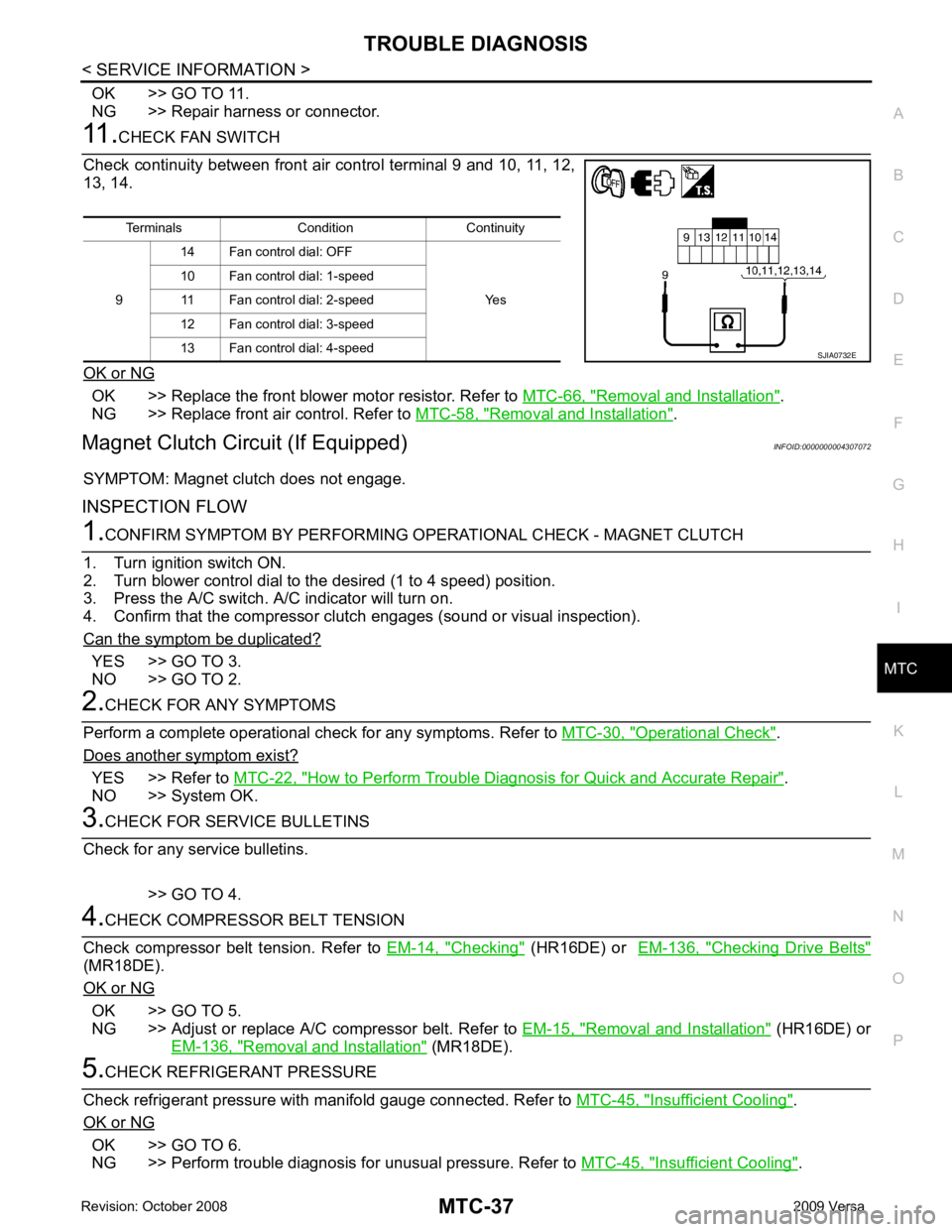
Terminals Condition Continuity
9 14 Fan control dial: OFF
Yes
10 Fan control dial: 1-speed
11 Fan control dial: 2-speed
12 Fan control dial: 3-speed
13 Fan control dial: 4-speed
Page 3923 of 4331
OK >> If the symptom still exists, perform
a complete operational check. Refer to MTC-30, " Operational
Check " . If other symptoms exist, refer to
MTC-22, " How to Perform Trouble Diagnosis for Quick
and Accurate Repair " .
NG >> Repair as necessary.
SYSTEM DESCRIPTION
Thermo control amp. controls A/C compressor operat ion by intake air temperature and signal from ECM.
The defrost A/C switch controls A/ C compressor operation by the BCM when the mode switch is turned to the
(DEF) position.
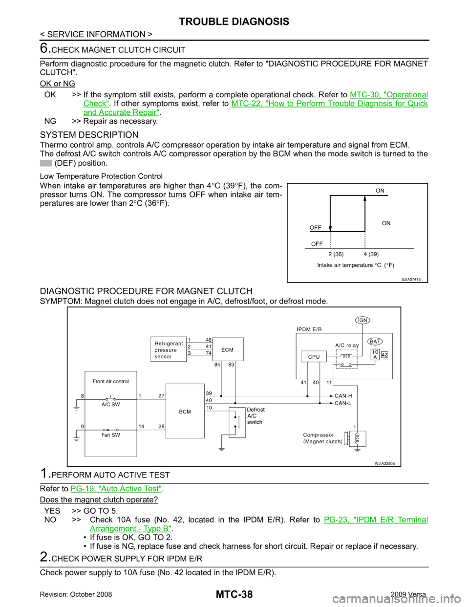
Low Temperature Protection Control
When intake air temperatures are higher than 4 °C (39 °F), the com-
pressor turns ON. The compressor turns OFF when intake air tem-
peratures are lower than 2 °C (36 °F).
DIAGNOSTIC PROCEDURE FOR MAGNET CLUTCH
SYMPTOM: Magnet clutch does not engage in A/C, defrost/foot, or defrost mode.Auto Active Test " .
Does the magnet clutch operate? YES >> GO TO 5.
NO >> Check 10A fuse (No. 42, located in the IPDM E/R). Refer to PG-23, " IPDM E/R Terminal
Arrangement - Type B " .
• If fuse is OK, GO TO 2.
• If fuse is NG, replace fuse and check harness for short circuit. Repair or replace if necessary.