2009 NISSAN TIIDA e control
[x] Cancel search: e controlPage 3754 of 4331
MA
N
O P
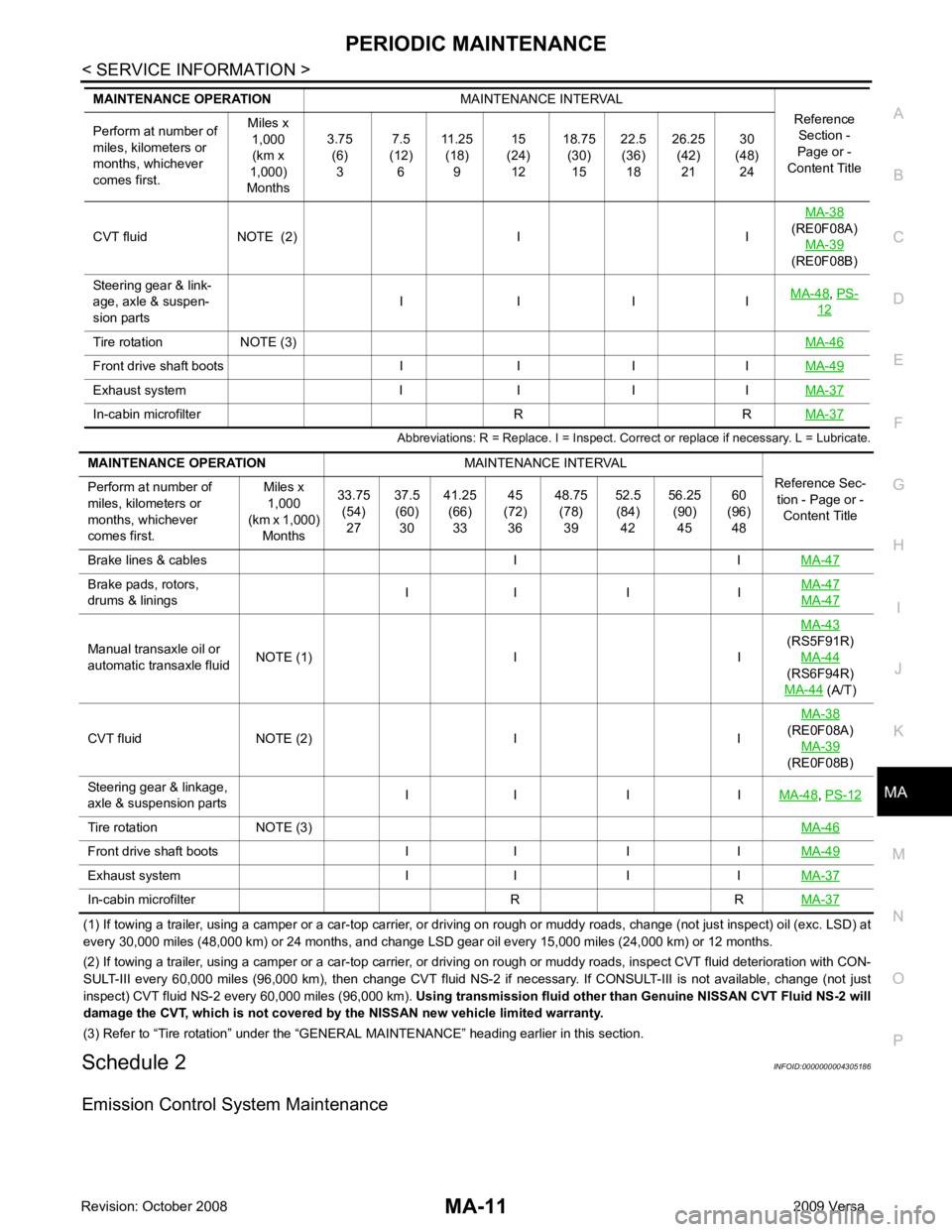
Abbreviations: R = Replace. I = Inspect. Corr
ect or replace if necessary. L = Lubricate.
(1) If towing a trailer, using a camper or a car-top carrier, or driving on rough or muddy roads, change (not just inspect) oil (exc. LSD) at
every 30,000 miles (48,000 km) or 24 months, and change LSD gear oil every 15,000 miles (24,000 km) or 12 months.
(2) If towing a trailer, using a camper or a car-top carrier, or driving on rough or muddy roads, inspect CVT fluid deteriorati on with CON-
SULT-III every 60,000 miles (96,000 km), then change CVT fluid NS-2 if necessary. If CONSULT-III is not available, change (not just
inspect) CVT fluid NS-2 every 60,000 miles (96,000 km). Using transmission fluid other than Genuine NISSAN CVT Fluid NS-2 will
damage the CVT, which is not covered by the NISSAN new vehicle limited warranty.
(3) Refer to “Tire rotation” under the “GENERAL MAINTENANCE” heading earlier in this section.
Schedule 2 INFOID:0000000004305186
Emission Control System Maintenance CVT fluid NOTE (2) I I
MA-38
(RE0F08A) MA-39
(RE0F08B)
Steering gear & link-
age, axle & suspen-
sion parts I I I I
MA-48 ,
PS- 12
Tire rotation NOTE (3)
MA-46Front drive shaft boots I I I I
MA-49Exhaust system I I I I
MA-37In-cabin microfilter R R
MA-37Brake pads, rotors,
drums & linings I I I I MA-47 MA-47
Manual transaxle oil or
automatic transaxle fluid NOTE (1) I I MA-43
(RS5F91R) MA-44
(RS6F94R)
MA-44 (A/T)
CVT fluid NOTE (2) I I MA-38
(RE0F08A)
MA-39
(RE0F08B)
Steering gear & linkage,
axle & suspension parts I I I I
MA-48 ,
PS-12 Tire rotation NOTE (3)
MA-46Front drive shaft boots I I I I
MA-49Exhaust system I I I I
MA-37In-cabin microfilter R R
MA-37
Page 3761 of 4331
MA-18< SERVICE INFORMATION >
ENGINE MAINTENANCE (HR16DE)
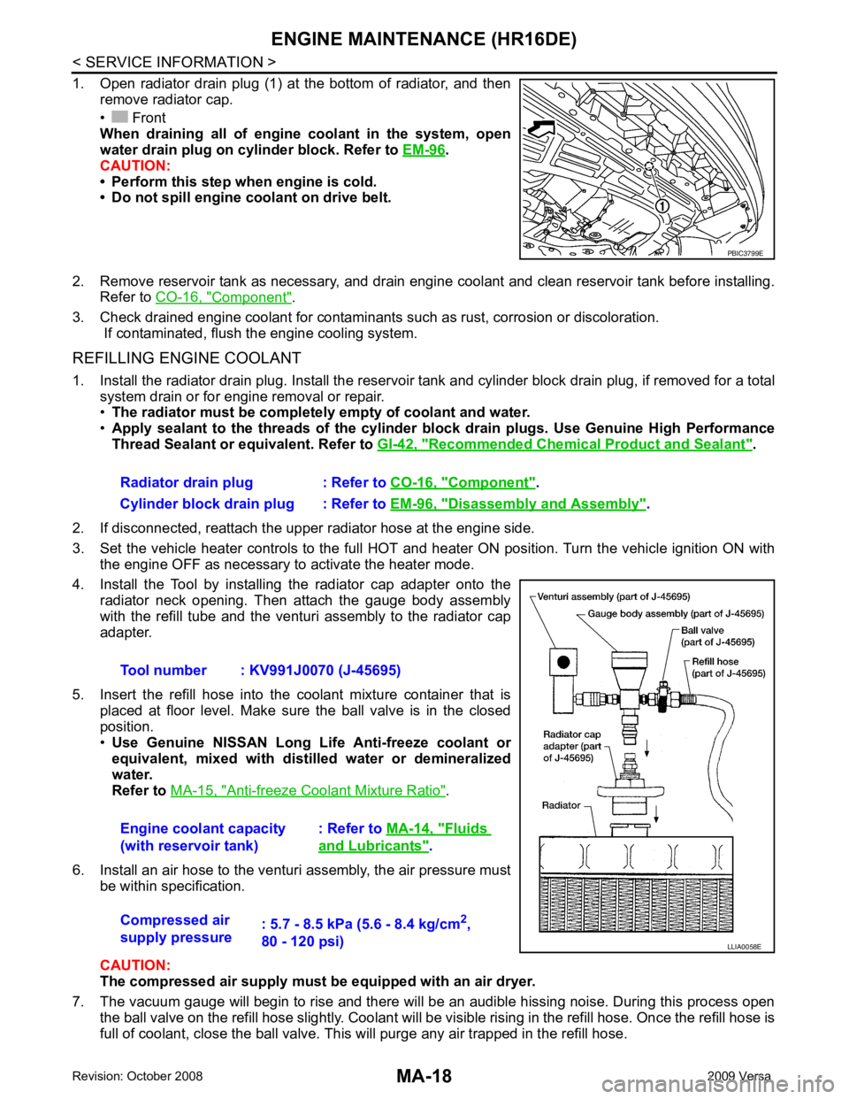
1. Open radiator drain plug (1) at the bottom of radiator, and then remove radiator cap.
• Front
When draining all of engine coolant in the system, open
water drain plug on cylinder block. Refer to EM-96 .
CAUTION:
• Perform this step when engine is cold.
• Do not spill engine coolant on drive belt.
2. Remove reservoir tank as necessary, and drain engine coolant and clean reservoir tank before installing. Refer to CO-16, " Component " .
3. Check drained engine coolant for contaminants such as rust, corrosion or discoloration. If contaminated, flush the engine cooling system.
REFILLING ENGINE COOLANT
1. Install the radiator drain plug. Install the reservoir tank and cylinder block drain plug, if removed for a total
system drain or for engine removal or repair.
• The radiator must be complete ly empty of coolant and water.
• Apply sealant to the threads of the cylinder bl ock drain plugs. Use Genuine High Performance
Thread Sealant or equivalent. Refer to GI-42, " Recommended Chemical Product and Sealant " .
2. If disconnected, reattach the upper radiator hose at the engine side.
3. Set the vehicle heater controls to the full HOT and heat er ON position. Turn the vehicle ignition ON with
the engine OFF as necessary to activate the heater mode.
4. Install the Tool by installing the radiator cap adapter onto the radiator neck opening. Then attach the gauge body assembly
with the refill tube and the venturi assembly to the radiator cap
adapter.
5. Insert the refill hose into the coolant mixture container that is placed at floor level. Make sure the ball valve is in the closed
position.
• Use Genuine NISSAN Long Life Anti-freeze coolant or
equivalent, mixed with distil led water or demineralized
water.
Refer to MA-15, " Anti-freeze Coolant Mixture Ratio " .
6. Install an air hose to the venturi assembly, the air pressure must be within specification.
CAUTION:
The compressed air supply must be equipped with an air dryer.
7. The vacuum gauge will begin to rise and there will be an audible hissing noise. During this process open the ball valve on the refill hose slightly. Coolant will be vi sible rising in the refill hose. Once the refill hose is
full of coolant, close the ball valve. This will purge any air trapped in the refill hose. PBIC3799E
Radiator drain plug : Refer to
CO-16, " Component " .
Cylinder block drain plug : Refer to EM-96, " Disassembly and Assembly " .
Tool number : KV991J0070 (J-45695)
Engine coolant capacity
(with reservoir tank) : Refer to
MA-14, " Fluids
and Lubricants " .
Compressed air
supply pressure : 5.7 - 8.5 kPa (5.6 - 8.4 kg/cm
2
,
80 - 120 psi) LLIA0058E
Page 3764 of 4331
ENGINE MAINTENANCE (HR16DE)
MA-21
< SERVICE INFORMATION >
C
D E
F
G H
I
J
K
M A
B MA
N
O P
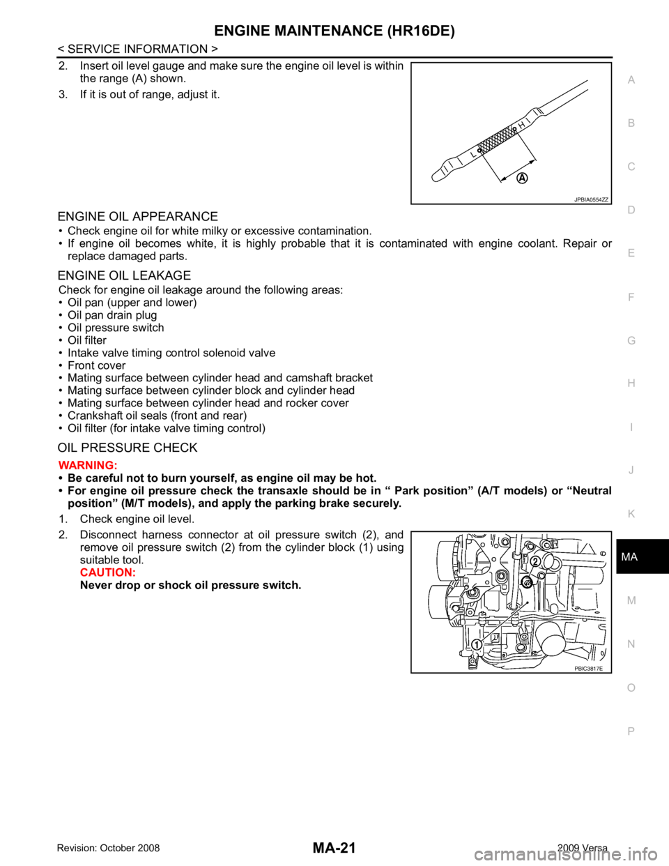
2. Insert oil level gauge and make sure the engine oil level is within
the range (A) shown.
3. If it is out of range, adjust it.
ENGINE OIL APPEARANCE • Check engine oil for white milky or excessive contamination.
• If engine oil becomes white, it is highly probable t hat it is contaminated with engine coolant. Repair or
replace damaged parts.
ENGINE OIL LEAKAGE Check for engine oil leakage around the following areas:
• Oil pan (upper and lower)
• Oil pan drain plug
• Oil pressure switch
• Oil filter
• Intake valve timing control solenoid valve
• Front cover
• Mating surface between cylinder head and camshaft bracket
• Mating surface between cylinder block and cylinder head
• Mating surface between cylinder head and rocker cover
• Crankshaft oil seals (front and rear)
• Oil filter (for intake valve timing control)
OIL PRESSURE CHECK WARNING:
• Be careful not to burn yoursel f, as engine oil may be hot.
• For engine oil pressure check the transaxle should be in “ Park position” (A/T models) or “Neutral
position” (M/T models), and apply the parking brake securely.
1. Check engine oil level.
2. Disconnect harness connector at oil pressure switch (2), and remove oil pressure switch (2) from the cylinder block (1) using
suitable tool.
CAUTION:
Never drop or shock oil pressure switch. JPBIA0554ZZ
PBIC3817E
Page 3770 of 4331
ENGINE MAINTENANCE (MR18DE)
MA-27
< SERVICE INFORMATION >
C
D E
F
G H
I
J
K
M A
B MA
N
O P
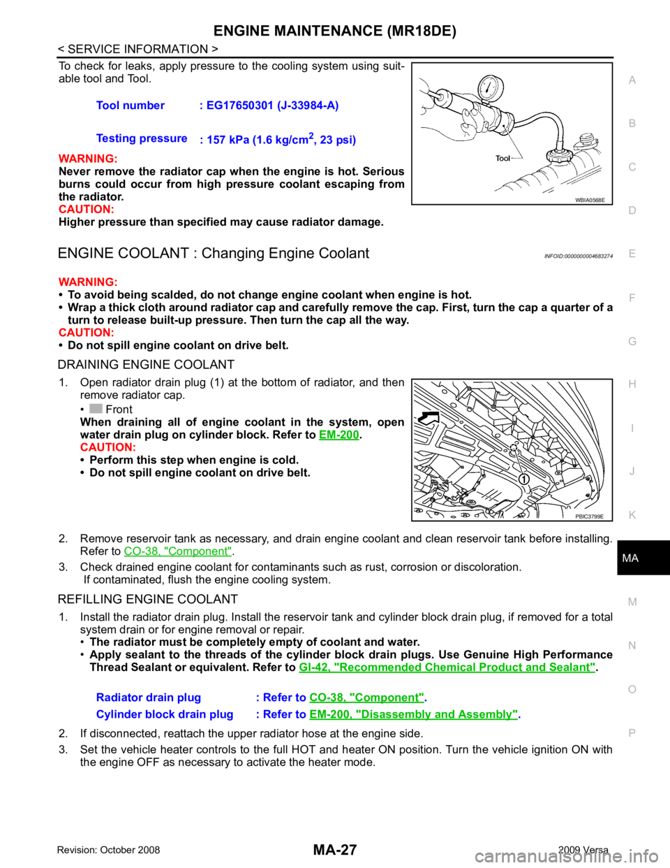
To check for leaks, apply pressure to the cooling system using suit-
able tool and Tool.
WARNING:
Never remove the radiator cap wh en the engine is hot. Serious
burns could occur from high pressure coolant escaping from
the radiator.
CAUTION:
Higher pressure than specified may cause radiator damage.
ENGINE COOLANT : Chang ing Engine Coolant INFOID:0000000004683274
WARNING:
• To avoid being scalded, do not change engine coolant when engine is hot.
• Wrap a thick cloth around radiator cap and carefully remove the cap. First, turn the cap a quarter of a
turn to release built-up pressure. Then turn the cap all the way.
CAUTION:
• Do not spill engine coolant on drive belt.
DRAINING ENGINE COOLANT 1. Open radiator drain plug (1) at the bottom of radiator, and then remove radiator cap.
• Front
When draining all of engine coolant in the system, open
water drain plug on cylinder block. Refer to EM-200 .
CAUTION:
• Perform this step when engine is cold.
• Do not spill engine coolant on drive belt.
2. Remove reservoir tank as necessary, and drain engi ne coolant and clean reservoir tank before installing.
Refer to CO-38, " Component " .
3. Check drained engine coolant for contaminants such as rust, corrosion or discoloration. If contaminated, flush the engine cooling system.
REFILLING ENGINE COOLANT 1. Install the radiator drain plug. Install the reservoir tank and cylinder block drain plug, if removed for a total
system drain or for engine removal or repair.
• The radiator must be complete ly empty of coolant and water.
• Apply sealant to the threads of the cylinder blo ck drain plugs. Use Genuine High Performance
Thread Sealant or equivalent. Refer to GI-42, " Recommended Chemical Product and Sealant " .
2. If disconnected, reattach the upper radiator hose at the engine side.
3. Set the vehicle heater controls to the full HOT and heat er ON position. Turn the vehicle ignition ON with
the engine OFF as necessary to activate the heater mode. Tool number : EG17650301 (J-33984-A)
Testing pressure : 157 kPa (1.6 kg/cm 2
, 23 psi) WBIA0568E
PBIC3799E
Radiator drain plug : Refer to
CO-38, " Component " .
Cylinder block drain plug : Refer to EM-200, " Disassembly and Assembly " .
Page 3773 of 4331
MA-30< SERVICE INFORMATION >
ENGINE MAINTENANCE (MR18DE)
AIR CLEANER FILTER : Changing Air Cleaner Filter INFOID:0000000004685431
REMOVAL
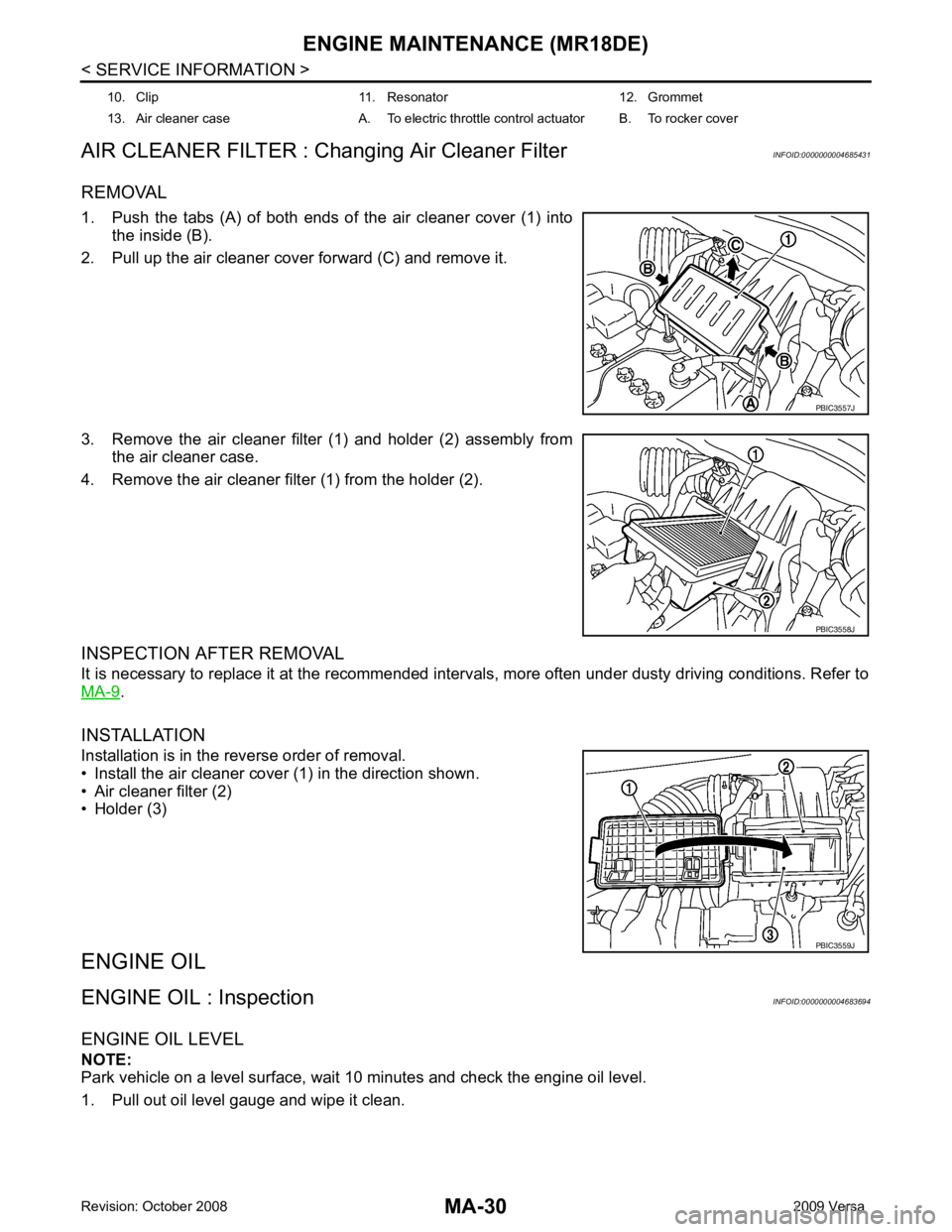
1. Push the tabs (A) of both ends of the air cleaner cover (1) into the inside (B).
2. Pull up the air cleaner cover forward (C) and remove it.
3. Remove the air cleaner filter (1) and holder (2) assembly from the air cleaner case.
4. Remove the air cleaner filter (1) from the holder (2).
INSPECTION AFTER REMOVAL
It is necessary to replace it at the recommended interv als, more often under dusty driving conditions. Refer to
MA-9 .
INSTALLATION
Installation is in the reverse order of removal.
• Install the air cleaner cover (1) in the direction shown.
• Air cleaner filter (2)
• Holder (3)
ENGINE OIL
ENGINE OIL : Inspection INFOID:0000000004683694
ENGINE OIL LEVEL
NOTE:
Park vehicle on a level surface, wait 10 minutes and check the engine oil level.
1. Pull out oil level gauge and wipe it clean. 10. Clip 11. Resonator 12. Grommet
13. Air cleaner case A. To electric throttle control actuator B. To rocker cover PBIC3557J
PBIC3558J
PBIC3559J
Page 3774 of 4331
ENGINE MAINTENANCE (MR18DE)
MA-31
< SERVICE INFORMATION >
C
D E
F
G H
I
J
K
M A
B MA
N
O P
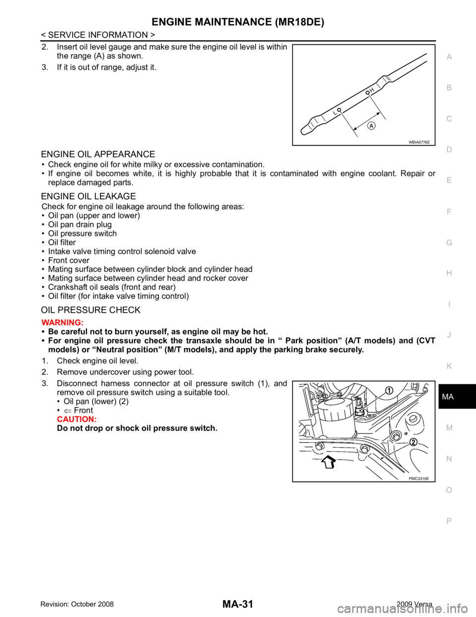
2. Insert oil level gauge and make sure the engine oil level is within
the range (A) as shown.
3. If it is out of range, adjust it.
ENGINE OIL APPEARANCE • Check engine oil for white milky or excessive contamination.
• If engine oil becomes white, it is highly probable t hat it is contaminated with engine coolant. Repair or
replace damaged parts.
ENGINE OIL LEAKAGE Check for engine oil leakage around the following areas:
• Oil pan (upper and lower)
• Oil pan drain plug
• Oil pressure switch
• Oil filter
• Intake valve timing control solenoid valve
• Front cover
• Mating surface between cylinder block and cylinder head
• Mating surface between cylinder head and rocker cover
• Crankshaft oil seals (front and rear)
• Oil filter (for intake valve timing control)
OIL PRESSURE CHECK WARNING:
• Be careful not to burn yoursel f, as engine oil may be hot.
• For engine oil pressure check the transaxle should be in “ Park position” (A/T models) and (CVT
models) or “Neutral position” (M/T mode ls), and apply the parking brake securely.
1. Check engine oil level.
2. Remove undercover using power tool.
3. Disconnect harness connector at oil pressure switch (1), and remove oil pressure switch using a suitable tool.
• Oil pan (lower) (2)
• ⇐ Front
CAUTION:
Do not drop or shock oil pressure switch. WBIA0776E
PBIC3310E
Page 3789 of 4331
MA-46< SERVICE INFORMATION >
CHASSIS AND BODY MAINTENANCE
WHEELS : Rotation INFOID:0000000004683838
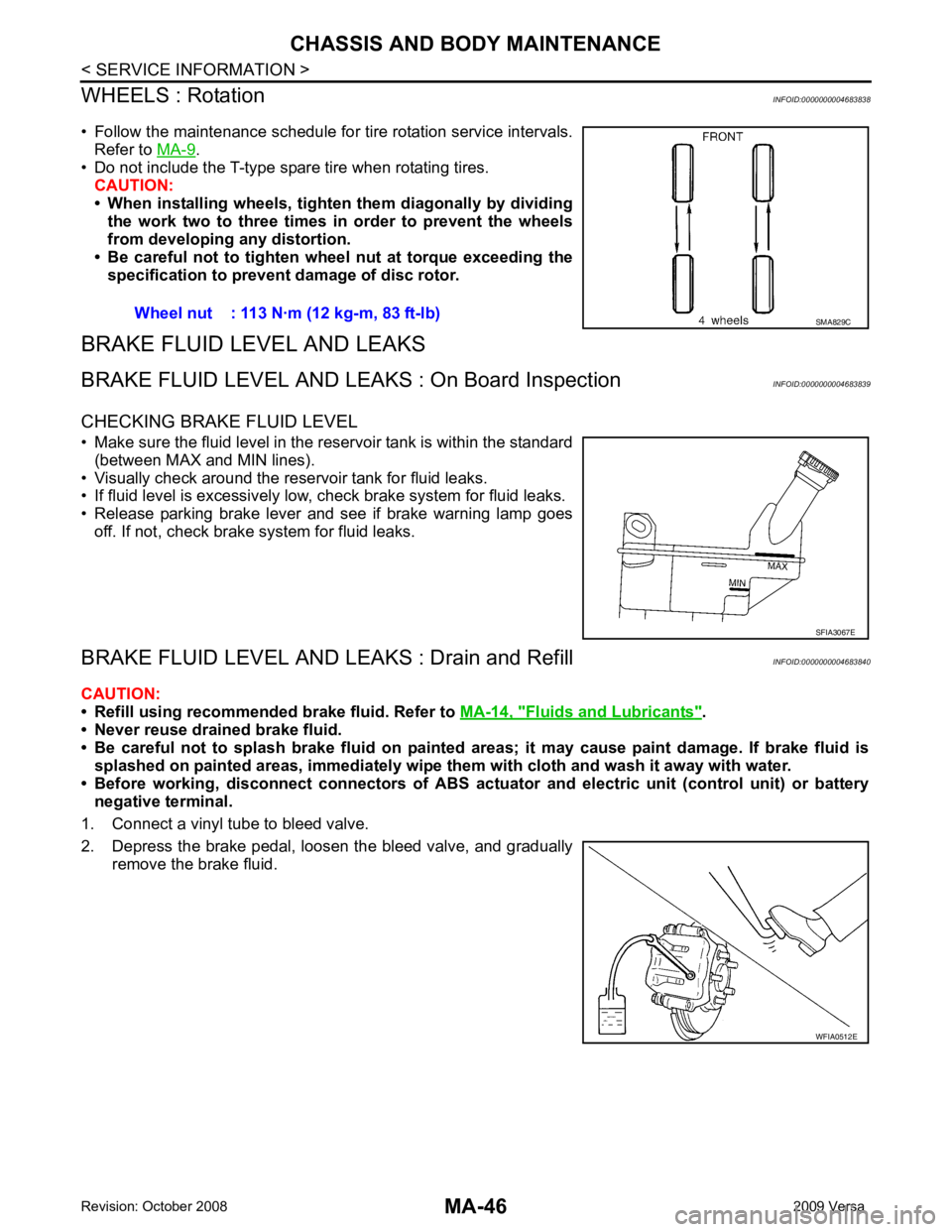
• Follow the maintenance schedule for tire rotation service intervals. Refer to MA-9 .
• Do not include the T-type spare tire when rotating tires.
CAUTION:
• When installing wheels, tighten them diagonally by dividing
the work two to three times in order to prevent the wheels
from developing any distortion.
• Be careful not to tighten wheel nut at torque exceeding the specification to prevent damage of disc rotor.
BRAKE FLUID LEVEL AND LEAKS
BRAKE FLUID LEVEL AND LEAK S : On Board Inspection INFOID:0000000004683839
CHECKING BRAKE FLUID LEVEL
• Make sure the fluid level in the reservoir tank is within the standard (between MAX and MIN lines).
• Visually check around the reservoir tank for fluid leaks.
• If fluid level is excessively low, check brake system for fluid leaks.
• Release parking brake lever and see if brake warning lamp goes off. If not, check brake system for fluid leaks.
BRAKE FLUID LEVEL AND LE AKS : Drain and Refill INFOID:0000000004683840
CAUTION:
• Refill using recommended brake fluid. Refer to MA-14, " Fluids and Lubricants " .
• Never reuse drained brake fluid.
• Be careful not to splash brake fluid on painted areas; it may cause paint damage. If brake fluid is
splashed on painted areas, immediately wipe th em with cloth and wash it away with water.
• Before working, disconnect connectors of ABS actua tor and electric unit (control unit) or battery
negative terminal.
1. Connect a vinyl tube to bleed valve.
2. Depress the brake pedal, loosen the bleed valve, and gradually remove the brake fluid.Wheel nut : 113 N·m (12 kg-m, 83 ft-lb) SMA829C
SFIA3067E
WFIA0512E
Page 3795 of 4331

MT
N
O P
CONTENTS
MANUAL TRANSAXLE
RS5F91R
SERVICE INFORMATION .. ..........................
3
PRECAUTIONS .............................................. .....3
Precaution for Supplemental Restraint System
(SRS) "AIR BAG" and "SEAT BELT PRE-TEN-
SIONER" ............................................................. ......
3
PREPARATION .............................................. .....4
Special Service Tools ........................................ ......4
Commercial Service Tools ................................. ......5
NOISE, VIBRATION AND HARSHNESS
(NVH) TROUBLESHOOTING ........................ .....
7
NVH Troubleshooting Chart ................................ ......7
DESCRIPTION ............................................... .....8
System Diagram .................................................. ......8
System Description ............................................. ......8
M/T OIL ........................................................... ....10
Draining ............................................................... ....10
Refilling ............................................................... ....10
Inspection ............................................................ ....10
SIDE OIL SEAL .............................................. ....11
Removal and Installation .........................................11
POSITION SWITCH ........................................ ....12
Checking ............................................................. ....12
CONTROL LINKAGE ..................................... ....13
Exploded View .................................................... ....13
Removal and Installation .........................................13
Inspection ............................................................ ....14
AIR BREATHER HOSE .................................. ....15
Exploded View .................................................... ....15
Removal and Installation .........................................15
TRANSAXLE ASSEMBLY ............................. ....16
Exploded View .................................................... ....16 Removal and Installation .....................................
....16
Disassembly and Assembly ................................. ....17
INPUT SHAFT AND GEAR ............................... 36
Disassembly and Assembly ................................. ....36
MAINSHAFT AND GEAR ................................. 37
Disassembly and Assembly ................................. ....37
FINAL DRIVE .................................................... 41
Disassembly and Assembly ................................. ....41
SHIFT CONTROL .............................................. 42
Inspection ............................................................ ....42
SERVICE DATA AND SPECIFICATIONS
(SDS) ................................................................. 43
General Specification .......................................... ....43
RS6F94R
SERVICE INFORMATION .. .........................44
PRECAUTIONS ................................................. 44
Precaution for Supplemental Restraint System
(SRS) "AIR BAG" and "SEAT BELT PRE-TEN-
SIONER" ............................................................. ....
44
Precaution for Procedure without Cowl Top Cover ....44
Precaution ........................................................... ....44
PREPARATION ................................................. 45
Special Service Tool ............................................ ....45
Commercial Service Tool .................................... ....47
NOISE, VIBRATION AND HARSHNESS
(NVH) TROUBLESHOOTING ........................... 49
NVH Troubleshooting Chart ................................ ....49
DESCRIPTION .................................................. 50
Cross-Sectional View ...... ........................................50
M/T OIL .............................................................. 52
Changing M/T Oil ................................................. ....52
Checking M/T Oil ................................................. ....52