2009 NISSAN TIIDA e control
[x] Cancel search: e controlPage 3597 of 4331
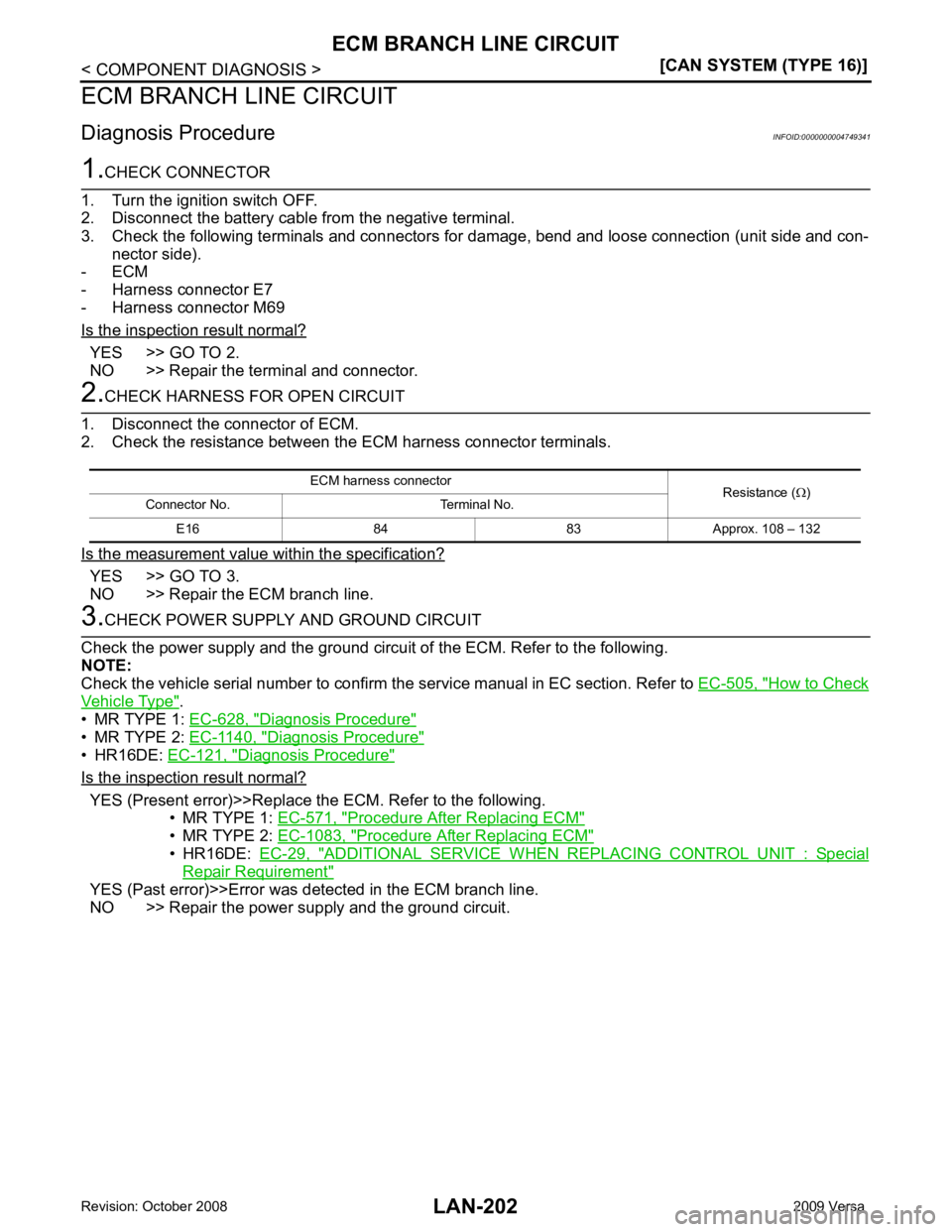
YES >> GO TO 2.
NO >> Repair the terminal and connector. YES >> GO TO 3.
NO >> Repair the ECM branch line. How to Check
Vehicle Type " .
• MR TYPE 1: EC-628, " Diagnosis Procedure "
• MR TYPE 2:
EC-1140, " Diagnosis Procedure "
• HR16DE:
EC-121, " Diagnosis Procedure "
Is the inspection result normal?
YES (Present error)>>Replace the ECM. Refer to the following.
• MR TYPE 1: EC-571, " Procedure After Replacing ECM "
• MR TYPE 2:
EC-1083, " Procedure After Replacing ECM "
• HR16DE:
EC-29, " ADDITIONAL SERVICE WHEN REPLACING CONTROL UNIT : Special
Repair Requirement "
YES (Past error)>>Error was detected in the ECM branch line.
NO >> Repair the power supply and the ground circuit. ECM harness connector
Resistance (Ω)
Connector No. Terminal No.
E16 84 83 Approx. 108 – 132
Page 3600 of 4331
LAN
N
O P
EPS BRANCH LINE CIRCUIT
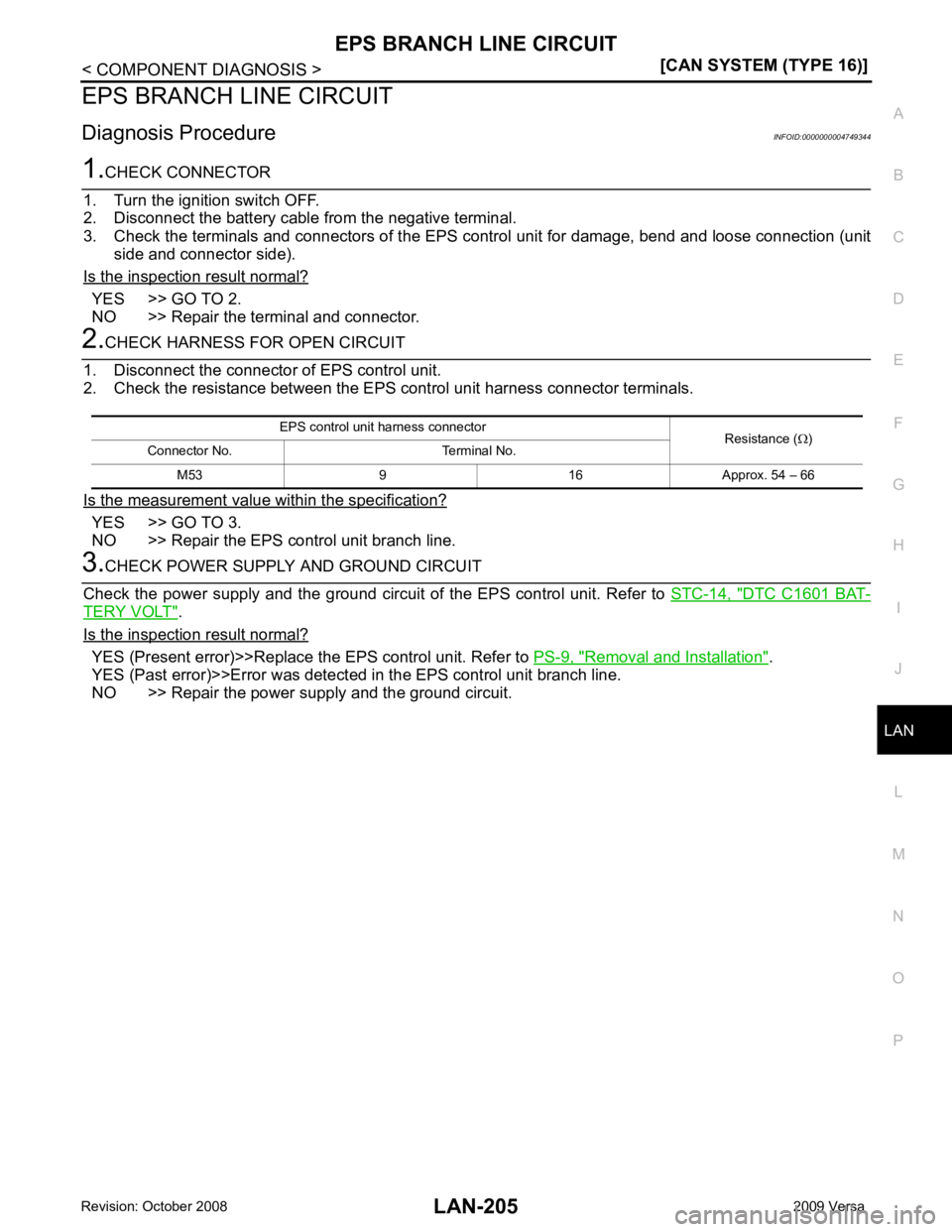
Diagnosis Procedure INFOID:0000000004749344YES >> GO TO 2.
NO >> Repair the terminal and connector. YES >> GO TO 3.
NO >> Repair the EPS control unit branch line. DTC C1601 BAT-
TERY VOLT " .
Is the inspection result normal? YES (Present error)>>Replace the EPS control unit. Refer to
PS-9, " Removal and Installation " .
YES (Past error)>>Error was detected in the EPS control unit branch line.
NO >> Repair the power supply and the ground circuit. EPS control unit harness connector
Resistance (Ω)
Connector No. Terminal No.
M53 9 16 Approx. 54 – 66
Page 3602 of 4331
LAN
N
O P
ABS BRANCH LINE CIRCUIT
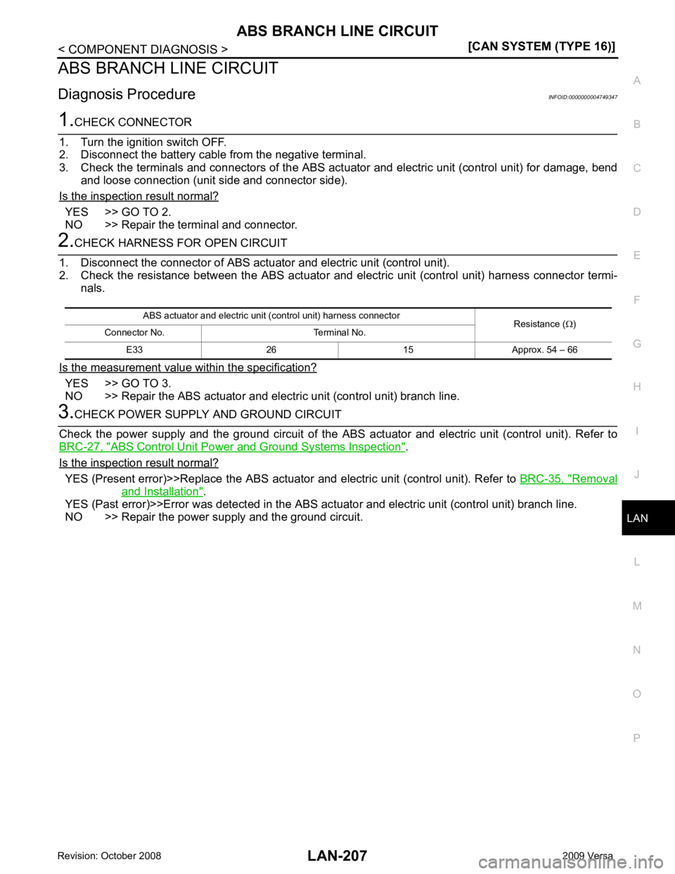
Diagnosis Procedure INFOID:0000000004749347YES >> GO TO 2.
NO >> Repair the terminal and connector. YES >> GO TO 3.
NO >> Repair the ABS actuator and electric unit (control unit) branch line. ABS Control Unit Power and Ground Systems Inspection " .
Is the inspection result normal? YES (Present error)>>Replace the ABS actuator
and electric unit (control unit). Refer to BRC-35, " Removal
and Installation " .
YES (Past error)>>Error was detected in the ABS ac tuator and electric unit (control unit) branch line.
NO >> Repair the power supply and the ground circuit. ABS actuator and electric unit (control unit) harness connector
Resistance (Ω)
Connector No. Terminal No.
E33 26 15 Approx. 54 – 66
Page 3609 of 4331
LT
N
O P
SERVICE INFORMATION
PRECAUTIONS
Precaution for Supplemental Restraint System (SRS) "AIR BAG" and "SEAT BELT
PRE-TENSIONER" INFOID:0000000004306519
The Supplemental Restraint System such as “A IR BAG” and “SEAT BELT PRE-TENSIONER”, used along
with a front seat belt, helps to reduce the risk or severi ty of injury to the driver and front passenger for certain
types of collision. This system includes seat belt switch inputs and dual stage front air bag modules. The SRS
system uses the seat belt switches to determine the front air bag deployment, and may only deploy one front
air bag, depending on the severity of a collision and w hether the front occupants are belted or unbelted.
Information necessary to service the system safely is included in the SRS and SB section of this Service Man-
ual.
WARNING:
• To avoid rendering the SRS inoper ative, which could increase the risk of personal injury or death in
the event of a collision which would result in air bag inflation, all maintenance must be performed by
an authorized NISSAN/INFINITI dealer.
• Improper maintenance, including in correct removal and installation of the SRS, can lead to personal
injury caused by unintentional act ivation of the system. For removal of Spiral Cable and Air Bag
Module, see the SRS section.
• Do not use electrical test equipm ent on any circuit related to the SRS unless instructed to in this
Service Manual. SRS wiring harnesses can be identi fied by yellow and/or orange harnesses or har-
ness connectors.
Precaution Necessary for Steering Wh eel Rotation After Battery Disconnect
INFOID:0000000004683900
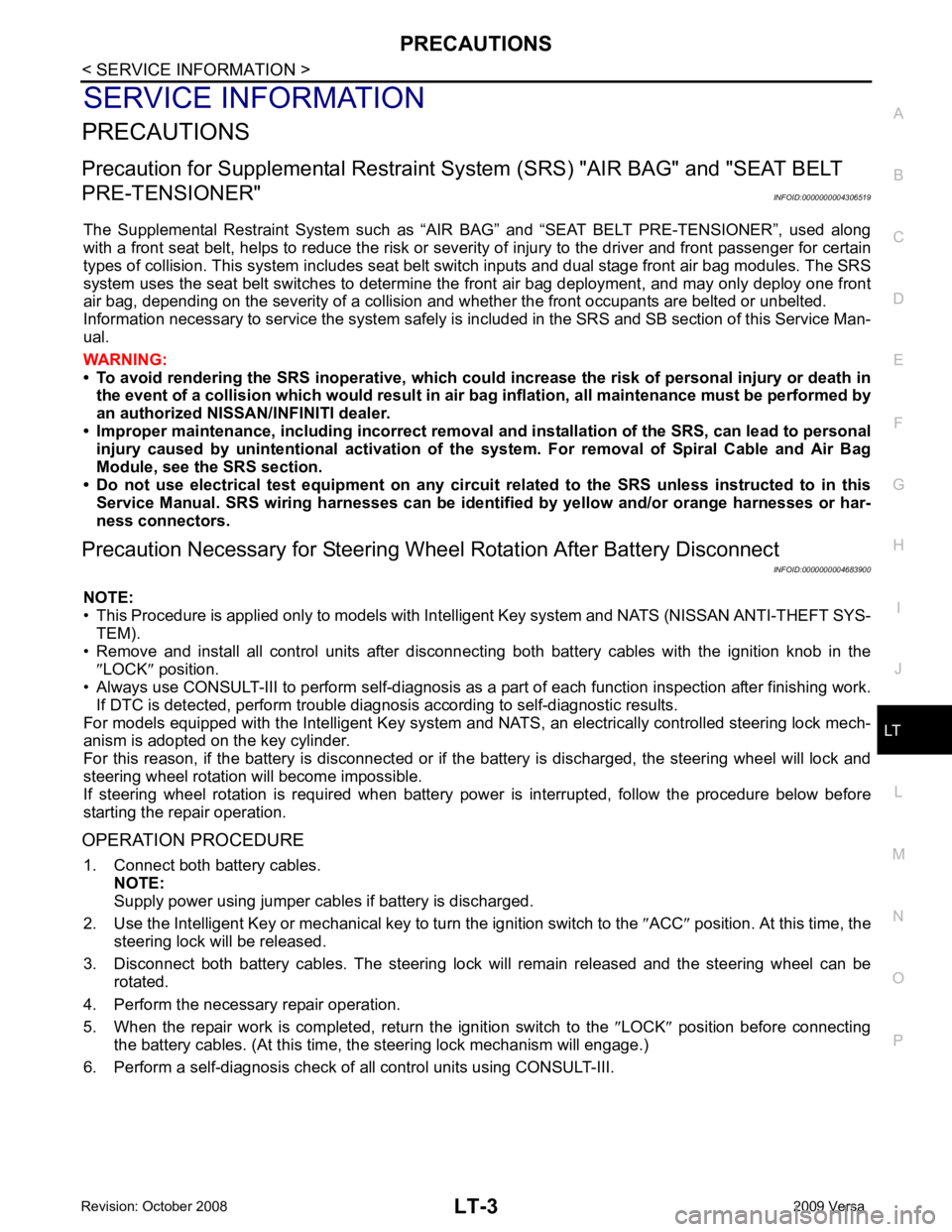
NOTE:
• This Procedure is applied only to models with Inte lligent Key system and NATS (NISSAN ANTI-THEFT SYS-
TEM).
• Remove and install all control units after disconnecti ng both battery cables with the ignition knob in the
″ LOCK ″ position.
• Always use CONSULT-III to perform self-diagnosis as a part of each function inspection after finishing work.
If DTC is detected, perform trouble diagnosis according to self-diagnostic results.
For models equipped with the Intelligent Key system and NATS , an electrically controlled steering lock mech-
anism is adopted on the key cylinder.
For this reason, if the battery is disconnected or if the battery is discharged, the steering wheel will lock and
steering wheel rotation will become impossible.
If steering wheel rotation is required when battery pow er is interrupted, follow the procedure below before
starting the repair operation.
OPERATION PROCEDURE 1. Connect both battery cables. NOTE:
Supply power using jumper cables if battery is discharged.
2. Use the Intelligent Key or mechanical key to turn the ignition switch to the ″ACC ″ position. At this time, the
steering lock will be released.
3. Disconnect both battery cables. The steering lock will remain released and the steering wheel can be
rotated.
4. Perform the necessary repair operation.
5. When the repair work is completed, return the ignition switch to the ″LOCK ″ position before connecting
the battery cables. (At this time, the steering lock mechanism will engage.)
6. Perform a self-diagnosis check of al l control units using CONSULT-III.
Page 3611 of 4331
LT
N
O P
• to BCM terminal 67
• to combination meter terminals 21, 22 and 23
• through grounds M57 and M61, and
• to IPDM E/R terminals 39 and 59
• through grounds E15 and E24.
HEADLAMP OPERATION
Low Beam Operation With the lighting switch in 2ND position, the BCM re ceives an input signal requesting the headlamps to illumi-
nate. The BCM then sends a signal, via the CAN comm unication lines, to the IPDM E/R requesting the low
beam headlamps be turned ON. The CPU located in the IPDM E/R controls ground to the headlamp low relay
coil, which when energized, directs power
• through 15A fuse (No. 41, located in IPDM E/R)
• through IPDM E/R terminal 54
• to headlamp RH terminal 3, and
• through 15A fuse (No. 40, located in IPDM E/R)
• through IPDM E/R terminal 52
• to headlamp LH terminal 3.
Ground is supplied
• to headlamp RH and LH terminals 2
• through grounds E15 and E24.
With power and ground supplied, low beam headlamps illuminate.
High Beam Operation/Flash-to-Pass Operation With the lighting switch in 2ND position and high beam s witch in the HIGH position, the BCM receives an input
signal requesting the headlamp high beams to illuminate. The flash to pass feature can be used any time and
also sends a signal to the BCM. This input signal is then communicated to the IPDM E/R and the combination
meter via the CAN communication. The CPU located in the IPDM E/R controls the headlamp high relays (LH
and RH), which when energized, directs power
• through 10A fuse (No. 34, located in IPDM E/R)
• through IPDM E/R terminal 56
• to headlamp RH terminal 1, and
• through 10A fuse (No. 35, located in IPDM E/R)
• through IPDM E/R terminal 55
• to headlamp LH terminal 1.
Ground is supplied
• to headlamp RH and LH terminal 2
• through grounds E15 and E24.
With power and ground supplied, the high beam headlamps illuminate.
The BCM sends a signal, via the CAN communication lines, to the combination meter requesting the high
beam indicator lamp be turned ON.
COMBINATION SWITCH READING FUNCTION Refer to BCS-3, " System Description " .
EXTERIOR LAMP BATTERY SAVER CONTROL Refer to LT-73, " System Description " .
CAN COMMUNICATION SYSTEM DESCRIPTION INFOID:0000000004306522
Refer to LAN-8 .
Page 3617 of 4331
LT
N
O P
How to Perform Trouble Diagnosis
INFOID:0000000004306527
1. Confirm the symptom or customer complaint.
2. Understand operation, description and function description. Refer to LT-4, " System Description " .
3. Perform the Preliminary Check. Refer to LT-11, " Preliminary Check " .
4. Check symptom and repair or replace the cause of the malfunction.
5. Do the headlamps operate normally? If YES, GO TO 6. If NO, GO TO 4.
6. INSPECTION END
Preliminary Check INFOID:0000000004306528
CHECK POWER SUPPLY AND GROUND CIRCUIT FOR BCM Refer to BCS-15, " BCM Power Supply and Ground Circuit Inspection " .
CHECK POWER SUPPLY AND GROUND CIRCUIT FOR IPDM E/R Refer to PG-26, " IPDM E/R Power/Ground Circuit Inspection " .
CONSULT-III Function (BCM) INFOID:0000000004306529
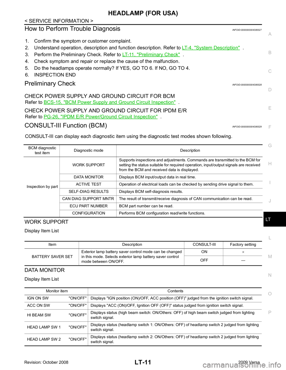
CONSULT-III can display each diagnostic item using the diagnostic test modes shown following.
WORK SUPPORT
Display Item List
DATA MONITOR
Display Item List BCM diagnostic
test item Diagnostic mode Description
Inspection by part WORK SUPPORT
Supports inspections and adjustments. Commands are transmitted to the BCM for
setting the status suitable for required operation, input/output signals are received
from the BCM and received data is displayed.
DATA MONITOR Displays BCM input/output data in real time. ACTIVE TEST Operation of electrical loads can be checked by sending drive signal to them.
SELF-DIAG RESULTS Displays BCM self-diagnosis results.
CAN DIAG SUPPORT MNTR The result of transmit/receive diagnosis of CAN communication can be read. ECU PART NUMBER BCM part number can be read.
CONFIGURATION Performs BCM configuration read/write functions. Item Description CONSULT-III Factory setting
BATTERY SAVER SET Exterior lamp battery saver control mode can be changed
in this mode. Selects exterior lamp battery saver control
mode between ON/OFF. ON
×
OFF — Monitor item Contents
IGN ON SW "ON/OFF" Displays "IGN position (ON)/OFF, ACC position (OFF)" judged from the ignition switch signal.
ACC ON SW "ON/OFF" Displays "ACC (ON)/OFF, Ignition OFF (OFF)" status judged from ignition switch signal.
HI BEAM SW "ON/OFF" Displays status (high beam switch: ON/Others: OFF) of high beam switch judged from lighting
switch signal.
HEAD LAMP SW 1 "ON/OFF" Displays status (headlamp switch 1: ON/Others: OFF) of headlamp switch 2 judged from lighting
switch signal.
HEAD LAMP SW 2 "ON/OFF" Displays status (headlamp switch 2: ON/Others: OFF) of headlamp switch 2 judged from lighting
switch signal.
Page 3631 of 4331
LT
N
O P
HEADLAMP (FOR CANADA)
- DAYTIME LIGHT SYSTEM -
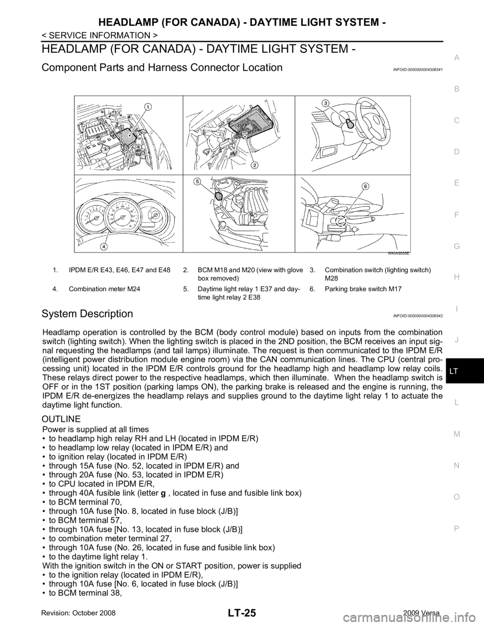
Component Parts and Har ness Connector Location INFOID:0000000004306541
System Description INFOID:0000000004306542
Headlamp operation is controlled by the BCM (body c ontrol module) based on inputs from the combination
switch (lighting switch). When the lighting switch is pl aced in the 2ND position, the BCM receives an input sig-
nal requesting the headlamps (and tail lamps) illuminate. The request is then communicated to the IPDM E/R
(intelligent power distribution module engine room) vi a the CAN communication lines. The CPU (central pro-
cessing unit) located in the IPDM E/R controls ground for the headlamp high and headlamp low relay coils.
These relays direct power to the respective headlamps , which then illuminate. When the headlamp switch is
OFF or in the 1ST position (parking lamps ON), the parking brake is released and the engine is running, the
IPDM E/R de-energizes the headlamp relays and supplies gr ound to the daytime light relay 1 to actuate the
daytime light function.
OUTLINE Power is supplied at all times
• to headlamp high relay RH and LH (located in IPDM E/R)
• to headlamp low relay (located in IPDM E/R) and
• to ignition relay (located in IPDM E/R)
• through 15A fuse (No. 52, located in IPDM E/R) and
• through 20A fuse (No. 53, located in IPDM E/R)
• to CPU located in IPDM E/R,
• through 40A fusible link (letter g , located in fuse and fusible link box)
• to BCM terminal 70,
• through 10A fuse [No. 8, located in fuse block (J/B)]
• to BCM terminal 57,
• through 10A fuse [No. 13, located in fuse block (J/B)]
• to combination meter terminal 27,
• through 10A fuse (No. 26, located in fuse and fusible link box)
• to the daytime light relay 1.
With the ignition switch in the ON or START position, power is supplied
• to the ignition relay (located in IPDM E/R),
• through 10A fuse [No. 6, located in fuse block (J/B)]
• to BCM terminal 38, 1. IPDM E/R E43, E46, E47 and E48 2. BCM M18 and M20 (view with glove
box removed)3. Combination switch (lighting switch)
M28
4. Combination meter M24 5. Daytime light relay 1 E37 and day- time light relay 2 E386. Parking brake switch M17
Page 3633 of 4331
LT
N
O P
• to IPDM E/R terminal 56,
• through 10A fuse (No. 34, located in IPDM E/R) and
• through both de-energized headlamp high relays
• to 10A fuse (No. 35, located in IPDM E/R),
• through IPDM E/R terminal 55
• to front combination lamp LH terminal high beam 1.
Ground is supplied
• to front combination lamp LH terminal 2
• through grounds E15 and E24,
• to daytime light relay 1 terminal 1
• through IPDM E/R terminal 6.
With power and ground supplied, high beam headlamps illuminate at reduced intensity.
COMBINATION SWITCH READING FUNCTION Refer to BCS-3, " System Description " .
EXTERIOR LAMP BATTERY SAVER CONTROL Refer to LT-73, " System Description " .
CAN Communication System Description INFOID:0000000004306543
Refer to LAN-8, " System Description " .