Page 536 of 4331

REMOTE KEYLESS ENTRY SYSTEM
BL-75
< SERVICE INFORMATION >
C
D E
F
G H
J
K L
M A
B BL
N
O P
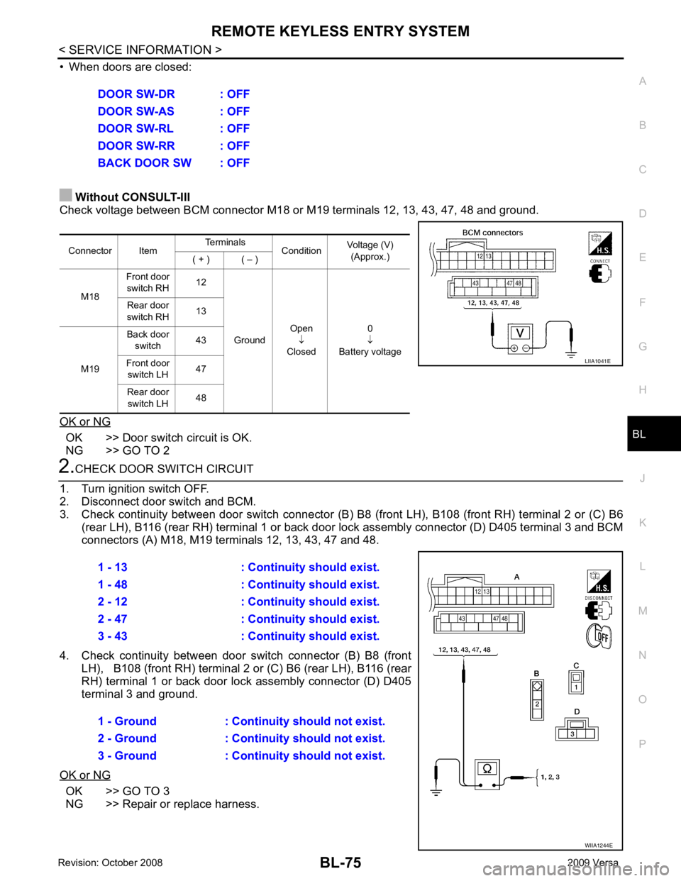
• When doors are closed:
Without CONSULT-III
Check voltage between BCM connector M18 or M19 terminals 12, 13, 43, 47, 48 and ground.
OK or NG OK >> Door switch circuit is OK.
NG >> GO TO 2 2.
CHECK DOOR SWITCH CIRCUIT
1. Turn ignition switch OFF.
2. Disconnect door switch and BCM.
3. Check continuity between door switch connector (B) B8 (front LH), B108 (front RH) terminal 2 or (C) B6
(rear LH), B116 (rear RH) terminal 1 or back door lock assembly connector (D) D405 terminal 3 and BCM
connectors (A) M18, M19 te rminals 12, 13, 43, 47 and 48.
4. Check continuity between door switch connector (B) B8 (front LH), B108 (front RH) terminal 2 or (C) B6 (rear LH), B116 (rear
RH) terminal 1 or back door lo ck assembly connector (D) D405
terminal 3 and ground.
OK or NG OK >> GO TO 3
NG >> Repair or replace harness. DOOR SW-DR : OFF
DOOR SW-AS : OFF
DOOR SW-RL : OFF
DOOR SW-RR : OFF
BACK DOOR SW : OFF
Connector Item Terminals
ConditionVoltage (V)
(Approx.)
( + ) ( – )
M18 Front door
switch RH 12
Ground Open
↓
Closed 0
↓
Battery voltage
Rear door
switch RH 13
M19 Back door
switch 43
Front door switch LH 47
Rear door switch LH 48 LIIA1041E
1 - 13 : Continuity should exist.
1 - 48 : Continuity should exist.
2 - 12 : Continuity should exist.
2 - 47 : Continuity should exist.
3 - 43 : Continuity should exist.
1 - Ground : Continuity should not exist.
2 - Ground : Continuity should not exist.
3 - Ground : Continuity should not exist. WIIA1244E
Page 538 of 4331

REMOTE KEYLESS ENTRY SYSTEM
BL-77
< SERVICE INFORMATION >
C
D E
F
G H
J
K L
M A
B BL
N
O P
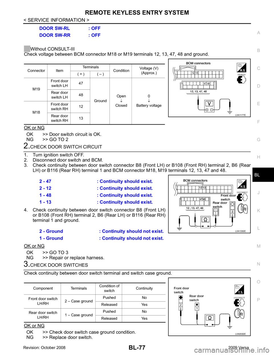
Without CONSULT-III
Check voltage between BCM connector M18 or M19 terminals 12, 13, 47, 48 and ground.
OK or NG OK >> Door switch circuit is OK.
NG >> GO TO 2 2.
CHECK DOOR SWITCH CIRCUIT
1. Turn ignition switch OFF.
2. Disconnect door switch and BCM.
3. Check continuity between door switch connector B8 (F ront LH) or B108 (Front RH) terminal 2, B6 (Rear
LH) or B116 (Rear RH) terminal 1 and BCM connector M18, M19 terminals 12, 13, 47 and 48.
4. Check continuity between door switch connector B8 (Front LH) or B108 (Front RH) terminal 2, B6 (Rear LH) or B116 (Rear RH)
terminal 1 and ground.
OK or NG OK >> GO TO 3
NG >> Repair or replace harness. 3.
CHECK DOOR SWITCHES
Check continuity between door switch terminal and switch case ground.
OK or NG OK >> Check door switch case ground condition.
NG >> Replace door switch. DOOR SW-RL : OFF
DOOR SW-RR : OFF
Connector Item Terminals
ConditionVoltage (V)
(Approx.)
( + ) ( – )
M19 Front door
switch LH 47
Ground Open
↓
Closed 0
↓
Battery voltage
Rear door
switch LH 48
M18 Front door
switch RH 12
Rear door
switch RH 13 LIIA1177E
2 - 47 : Continuity should exist.
2 - 12 : Continuity should exist.
1 - 48 : Continuity should exist.
1 - 13 : Continuity should exist.
2 - Ground : Continuity should not exist.
1 - Ground : Continuity should not exist. LIIA1350E
Component Terminals
Condition of
switch Continuity
Front door switch LH/RH 2 – Case ground Pushed No
Released Yes
Rear door switch LH/RH 1 – Case ground Pushed No
Released Yes LIIA0550E
Page 540 of 4331
BL
N
O P
Horn Function Check
INFOID:0000000004305023
First perform the “SELF-DIAG RESULTS” in “BCM” with CONSULT-III, then perform the trouble diagnosis of
malfunction system indicated “SELF-DI AG RESULTS” of “BCM”. Refer to BCS-17, " CAN Communication
Inspection Using CONSULT-III (Self-Diagnosis) " .
OK >> GO TO 2
NG >> Check horn circuit. Refer to WW-38 .
OK >> Replace IPDM E/R. Refer to
PG-27, " Removal and
Installation of IPDM E/R " .
NG >> GO TO 3 OK >> Check condition of harness and connector.
NG >> Repair or replace harness.
Interior Lamp and Ignition Key hole Illumination Function Check INFOID:0000000004305024YES >> Replace BCM. Refer to
BCS-18, " Removal and Installation of BCM " .
NO >> Check interior lamp circuit. Refer to LT-91 .
Terminals
Voltage (V)
(Approx.)
(+)
(–)
IPDM E/R connector Terminal
E46 45 Ground Battery voltage
Page 543 of 4331

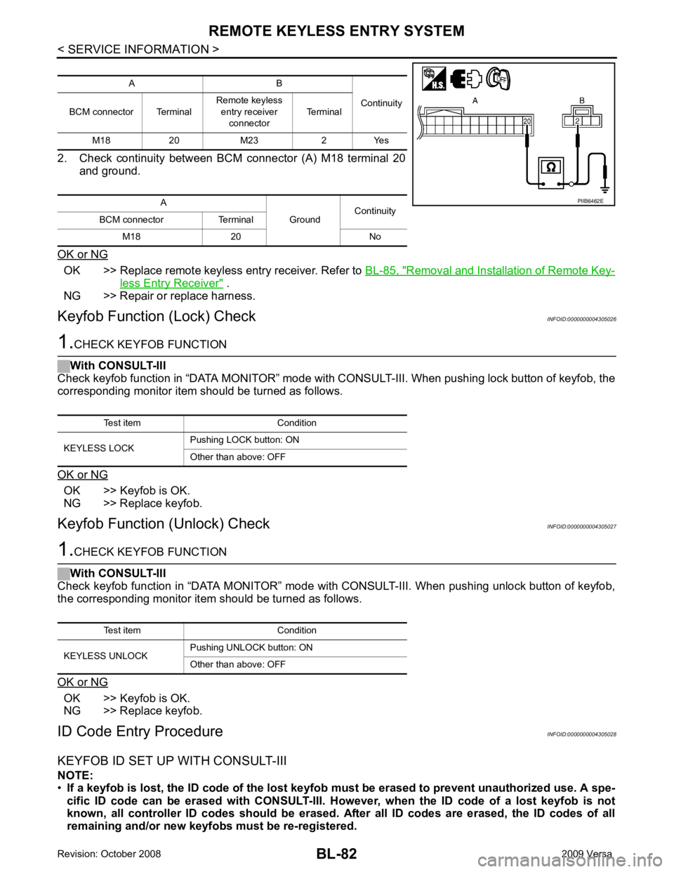
OK >> Replace remote keyless entry receiver. Refer to
BL-85, " Removal and Installation of Remote Key-
less Entry Receiver " .
NG >> Repair or replace harness.
Keyfob Function (Lock) Check INFOID:0000000004305026OK >> Keyfob is OK.
NG >> Replace keyfob.
Keyfob Function (Unlock) Check INFOID:0000000004305027OK >> Keyfob is OK.
NG >> Replace keyfob.
ID Code Entry Procedure INFOID:0000000004305028
KEYFOB ID SET UP WITH CONSULT-III
NOTE:
• If a keyfob is lost, the ID code of the lost keyfob must be erased to prevent unauthorized use. A spe-
cific ID code can be erased with CONSULT-III. Ho wever, when the ID code of a lost keyfob is not
known, all controller ID codes should be erased. After all ID codes are erased, the ID codes of all
remaining and/or new keyfobs must be re-registered. A B
Continuity
BCM connector Terminal Remote keyless
entry receiver
connector Terminal
M18 20 M23 2 Yes
A GroundContinuity
BCM connector Terminal
M18 20 No Test item Condition
KEYLESS UNLOCK Pushing UNLOCK button: ON
Other than above: OFF
Page 588 of 4331
BL
N
O P
OK or NG OK >> GO TO 2
NG >> Repair or replace Intelligent Key power supply circuit. OK >> Power supply and ground circuits are OK.
NG >> Repair or replace the Intelligent Key unit ground circuit.
Key Switch (Intelligent Key Unit Input) Check INFOID:0000000004305047OK >> Key switch circuit is OK.
NG >> GO TO 2 Terminals
Condition of key switch Voltage (V)
(Approx.)
(+)
(–)
Intelligent Key
unit connector Terminal
M52 7 Ground Insert mechanical key
into ignition switch Battery voltage
Remove mechanical
key from ignition switch 0
Page 589 of 4331
OK >> GO TO 3
NG >> Repair or replace key switch and ignition knob switch power supply circuit. OK >> GO TO 4
NG >> Replace key cylinder assembly (built-in key switch). OK >> Check the condition of harness and harness connector.
NG >> Repair or replace harness between Intelligent Key unit and key switch and ignition knob switch.
Key Switch (BCM Input) Check INFOID:0000000004305048
Page 590 of 4331

INTELLIGENT KEY SYSTEM
BL-129
< SERVICE INFORMATION >
C
D E
F
G H
J
K L
M A
B BL
N
O P
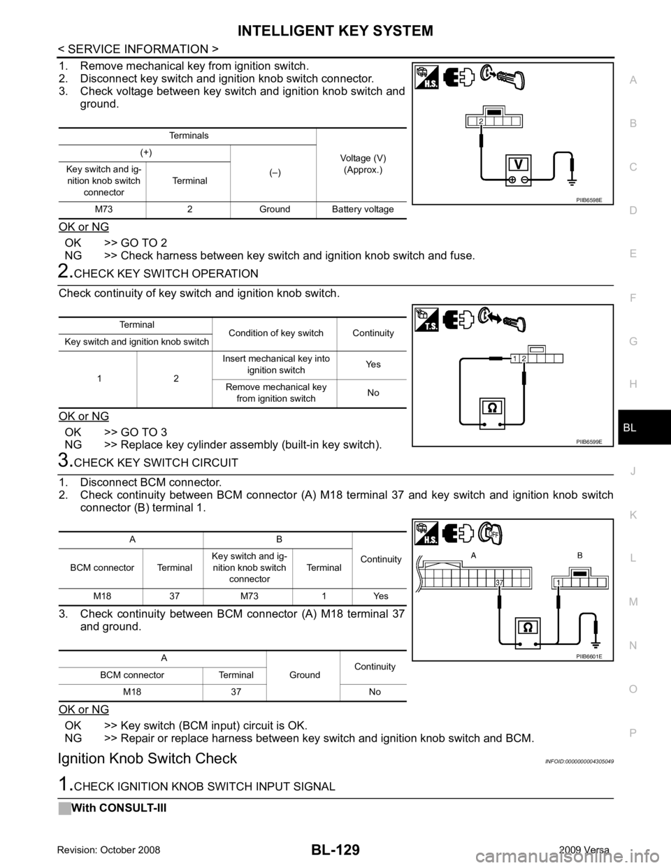
1. Remove mechanical key from ignition switch.
2. Disconnect key switch and i gnition knob switch connector.
3. Check voltage between key switch and ignition knob switch and
ground.
OK or NG OK >> GO TO 2
NG >> Check harness between key switch and ignition knob switch and fuse. 2.
CHECK KEY SWITCH OPERATION
Check continuity of key switch and ignition knob switch.
OK or NG OK >> GO TO 3
NG >> Replace key cylinder assembly (built-in key switch). 3.
CHECK KEY SWITCH CIRCUIT
1. Disconnect BCM connector.
2. Check continuity between BCM connector (A) M18 terminal 37 and key switch and ignition knob switch
connector (B) terminal 1.
3. Check continuity between BCM connector (A) M18 terminal 37 and ground.
OK or NG OK >> Key switch (BCM input) circuit is OK.
NG >> Repair or replace harness between key switch and ignition knob switch and BCM.
Ignition Knob Switch Check INFOID:00000000043050491.
CHECK IGNITION KNOB SWITCH INPUT SIGNAL
With CONSULT-III Terminals
Voltage (V)(Approx.)
(+)
(–)
Key switch and ig-
nition knob switch
connector Terminal
M73 2 Ground Battery voltage PIIB6598E
Terminal
Condition of key switch Continuity
Key switch and ignition knob switch
1 2 Insert mechanical key into
ignition switch Yes
Remove mechanical key from ignition switch No PIIB6599E
A B
Continuity
BCM connector Terminal Key switch and ig-
nition knob switch connector Terminal
M18 37 M73 1 Yes
A GroundContinuity
BCM connector Terminal
M18 37 No PIIB6601E
Page 591 of 4331
OK >> Ignition knob switch circuit is OK.
NG >> GO TO 2 OK >> GO TO 3
NG >> Repair or replace key switch and ignition knob switch power supply circuit. OK >> GO TO 4
NG >> Replace key switch and ignition knob switch. Monitor item Condition
PUSH SW Ignition switch is pressed: ON
Ignition switch is released: OFF Terminals
Condition of key switch Voltage (V)
(Approx.)
(+)
(–)
Intelligent Key unit
connector Terminal
M52 27 Ground Ignition switch is
pressed Battery voltage
Ignition switch is released 0