2009 NISSAN LATIO air condition
[x] Cancel search: air conditionPage 468 of 4331
BL
N
O P
SQUEAK AND RATTLE TROUBLE DIAGNOSES
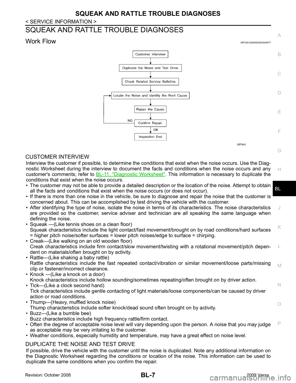
Work Flow INFOID:0000000004304977
CUSTOMER INTERVIEW Interview the customer if possible, to determine the c onditions that exist when the noise occurs. Use the Diag-
nostic Worksheet during the interv iew to document the facts and conditions when the noise occurs and any
customer's comments; refer to BL-11, " Diagnostic Worksheet " . This information is necessary to duplicate the
conditions that exist when the noise occurs.
• The customer may not be able to provide a detailed descr iption or the location of the noise. Attempt to obtain
all the facts and conditions that exist when the noise occurs (or does not occur).
• If there is more than one noise in the vehicle, be sure to diagnose and repair the noise that the customer is
concerned about. This can be accomplished by test driving the vehicle with the customer.
• After identifying the type of noise, isolate the noise in terms of its characteristics. The noise characteristics
are provided so the customer, service adviser and technician are all speaking the same language when
defining the noise.
• Squeak —(Like tennis shoes on a clean floor)
Squeak characteristics include the light contact/fast movement/brought on by road conditions/hard surfaces
= higher pitch noise/softer surfaces = lower pitch noises/edge to surface = chirping.
• Creak—(Like walking on an old wooden floor)
Creak characteristics include firm contact/slow mo vement/twisting with a rotational movement/pitch depen-
dent on materials/often brought on by activity.
• Rattle—(Like shaking a baby rattle)
Rattle characteristics include the fast repeated contac t/vibration or similar movement/loose parts/missing
clip or fastener/incorrect clearance.
• Knock —(Like a knock on a door)
Knock characteristics include hollow sounding/someti mes repeating/often brought on by driver action.
• Tick—(Like a clock second hand) Tick characteristics include gentle contacting of li ght materials/loose components/can be caused by driver
action or road conditions.
• Thump—(Heavy, muffled knock noise) Thump characteristics include softer k nock/dead sound often brought on by activity.
• Buzz—(Like a bumble bee)
Buzz characteristics include high frequency rattle/firm contact.
• Often the degree of acceptable noise level will vary depending upon the person. A noise that you may judge as acceptable may be very irritating to the customer.
• Weather conditions, especially humidity and temperature, may have a great effect on noise level.
DUPLICATE THE NOISE AND TEST DRIVE If possible, drive the vehicle with the customer until the noise is duplicated. Note any additional information on
the Diagnostic Worksheet regarding the conditions or lo cation of the noise. This information can be used to
duplicate the same conditions when you confirm the repair.
Page 470 of 4331

BL
N
O P
SILICONE GREASE
Used instead of UHMW tape that will be visible or not fit.
Note: Will only last a few months.
SILICONE SPRAY
Use when grease cannot be applied.
DUCT TAPE
Use to eliminate movement.
CONFIRM THE REPAIR Confirm that the cause of a noise is repaired by test driving the vehicle. Operate the vehicle under the same
conditions as when the noise originally occurred. Refer to the notes on the Diagnostic Worksheet.
Generic Squeak and Rattle Troubleshooting INFOID:0000000004304978
Refer to Table of Contents for specific component removal and installation information.
INSTRUMENT PANEL Most incidents are caused by contact and movement between:
1. The cluster lid A and instrument panel
2. Acrylic lens and combination meter housing
3. Instrument panel to front pillar garnish
4. Instrument panel to windshield
5. Instrument panel mounting pins
6. Wiring harnesses behind the combination meter
7. A/C defroster duct and duct joint
These incidents can usually be located by tapping or moving the components to duplicate the noise or by
pressing on the components while driving to stop the noi se. Most of these incidents can be repaired by apply-
ing felt cloth tape or silicone spray (in hard to reach areas). Urethane pads can be used to insulate wiring har-
ness.
CAUTION:
Do not use silicone spray to isolate a squeak or ra ttle. If you saturate the area with silicone, you will
not be able to recheck the repair.
CENTER CONSOLE Components to pay attention to include:
1. Shifter assembly cover to finisher
2. A/C control unit and cluster lid C
3. Wiring harnesses behind audio and A/C control unit
The instrument panel repair and isolation pr ocedures also apply to the center console.
DOORS Pay attention to the:
1. Finisher and inner panel making a slapping noise
2. Inside handle escutcheon to door finisher
3. Wiring harnesses tapping
4. Door striker out of alignment causing a popping noise on starts and stops
Tapping or moving the components or pressing on them wh ile driving to duplicate the conditions can isolate
many of these incidents. You can usually insulate the ar eas with felt cloth tape or insulator foam blocks from
the NISSAN Squeak and Rattle Kit (J-43980) to repair the noise.
TRUNK Trunk noises are often caused by a loose jack or loose items put into the trunk by the owner.
In addition look for:
1. Trunk lid bumpers out of adjustment
2. Trunk lid striker out of adjustment
3. The trunk lid torsion bars knocking together
4. A loose license plate or bracket
Page 502 of 4331

BL
N
O P
1: With Intelligent Key
2: Without Intelligent Key
3: Hatchback without Intelligent Key
4: Sedan without Intelligent Key
5: Hatchback
6: Sedan
7: With power door locks
8: With power windows
Work Flow INFOID:0000000004304994
1. Check the symptom and customer's requests.
2. Understand the outline of system. Refer to BL-23, " System Description " .
3. According to the trouble diagnosis chart, repair or replace the cause of the malfunction. Refer to BL-119," Trouble Diagnosis Symptom Chart " .
4. Does power door lock system operate normally? OK: GO TO 5, NG: GO TO 3.
5. Inspection End.
CONSULT-III Function (BCM) INFOID:0000000004304995
CONSULT-III can display each diagnostic item using the diagnostic test modes shown following. 65
7
SBAll door lock actuators
(lock) Output OFFOFF (neutral) 0V
ON (lock) Battery voltage
66 7
GFront door lock actua-
tor RH, rear door lock
actuators LH/RH (un-
lock) Output OFFOFF (neutral) 0V
ON (unlock) Battery voltage
67 B Ground Input ON — 0V
68 8
LPower window power
supply (RAP) Output —Ignition switch ON Battery voltage
Within 45 seconds after igni-
tion switch OFF Battery voltage
More than 45 seconds after ig-
nition switch OFF 0V
When front door LH or RH is
open or power window timer
operates 0V
69 8
P Battery power supply
OutputOFF
— Battery voltage
70 Y Battery power supply Input OFF — Battery voltage
Terminal
Wire
color Signal name Signal
input/
output Measuring condition
Reference value or waveform
(Approx.)
Ignition
switch Operation or condition
Page 505 of 4331
BL-44< SERVICE INFORMATION >
POWER DOOR LOCK SYSTEM2.
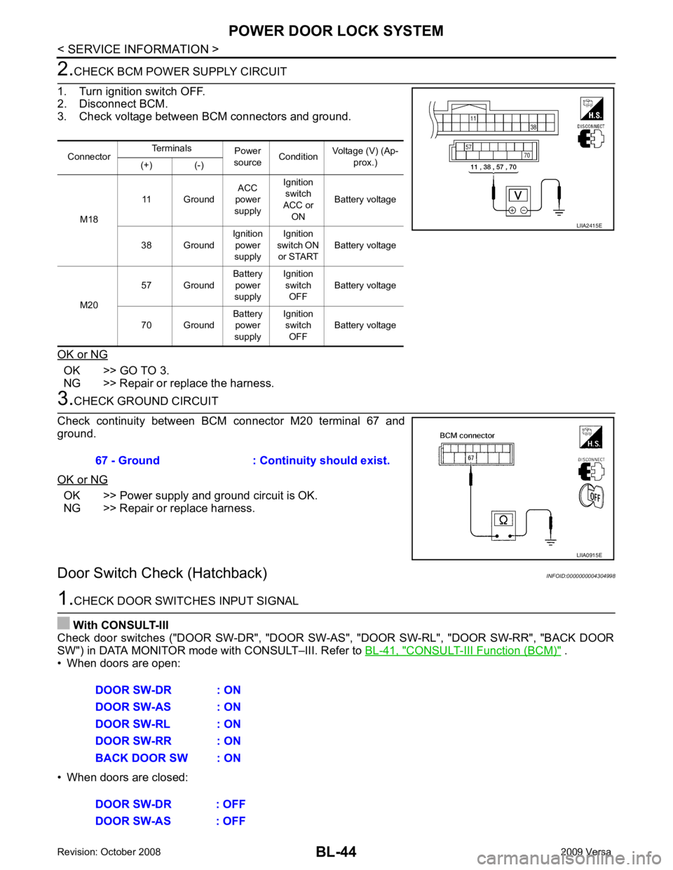
CHECK BCM POWER SUPPLY CIRCUIT
1. Turn ignition switch OFF.
2. Disconnect BCM.
3. Check voltage between BCM connectors and ground.
OK or NG OK >> GO TO 3.
NG >> Repair or replace the harness. 3.
CHECK GROUND CIRCUIT
Check continuity between BCM connector M20 terminal 67 and
ground.
OK or NG OK >> Power supply and ground circuit is OK.
NG >> Repair or replace harness.
Door Switch Check (Hatchback) INFOID:00000000043049981.
CHECK DOOR SWITCHES INPUT SIGNAL
With CONSULT-III
Check door switches ("DOOR SW-DR", "DOOR SW-AS", "DOOR SW-RL", "DOOR SW-RR", "BACK DOOR
SW") in DATA MONITOR mode with CONSULT–III. Refer to BL-41, " CONSULT-III Function (BCM) " .
• When doors are open:
• When doors are closed: Connector
Terminals
Power
source Condition Voltage (V) (Ap-
prox.)
(+) (-)
M18 11 Ground
ACC
power
supply Ignition
switch
ACC or ON Battery voltage
38 Ground Ignition
power
supply Ignition
switch ON
or START Battery voltage
M20 57 Ground
Battery
power
supply Ignition
switch OFF Battery voltage
70 Ground Battery
power
supply Ignition
switch OFF Battery voltage LIIA2415E
67 - Ground : Continuity should exist.
LIIA0915E
DOOR SW-DR : ON
DOOR SW-AS : ON
DOOR SW-RL : ON
DOOR SW-RR : ON
BACK DOOR SW : ON
DOOR SW-DR : OFF
DOOR SW-AS : OFF
Page 509 of 4331
OK >> GO TO 3
NG >> Repair or replace harness. OK >> Check door switch case ground condition.
NG >> Replace door switch.
Key Switch (I nsert) Check INFOID:0000000004305000 CONSULT-III
Function (BCM) " .
• When key is inserted into ignition key cylinder:
• When key is removed from ignition key cylinder:
Without CONSULT-III
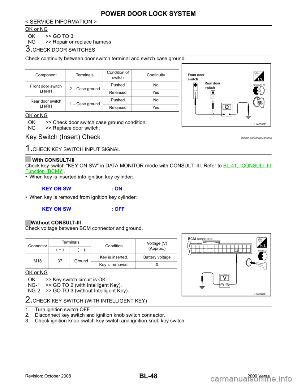
Check voltage between BCM connector and ground.
OK or NG OK >> Key switch circuit is OK.
NG-1 >> GO TO 2 (with Intelligent Key).
NG-2 >> GO TO 3 (without Intelligent Key).
Page 518 of 4331
BL
N
O P
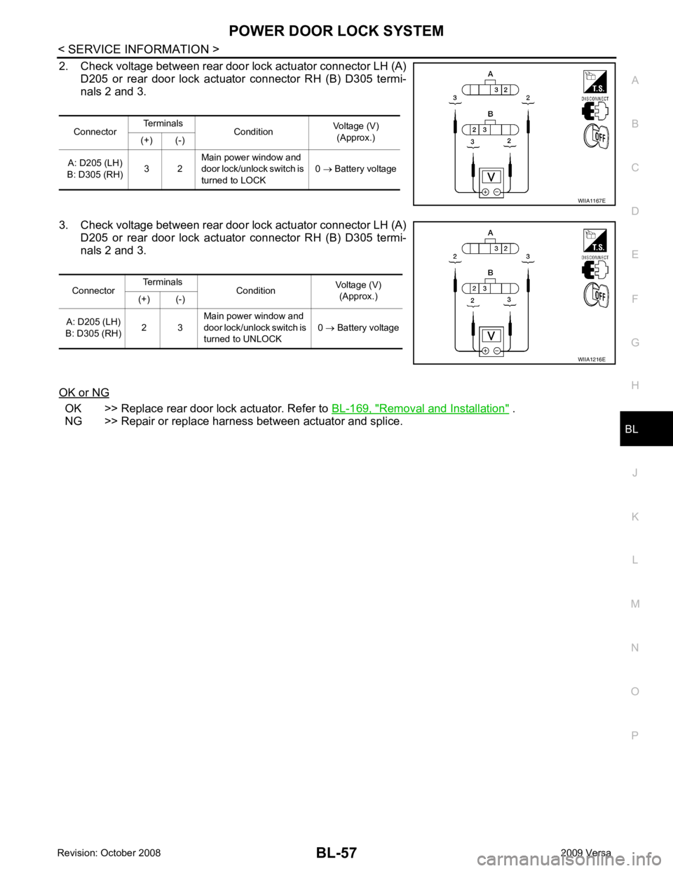
2. Check voltage between rear door lock actuator connector LH (A)
D205 or rear door lock actuator connector RH (B) D305 termi-
nals 2 and 3.
3. Check voltage between rear door lock actuator connector LH (A) D205 or rear door lock actuator connector RH (B) D305 termi-
nals 2 and 3.
OK or NG OK >> Replace rear door lock actuator. Refer to
BL-169, " Removal and Installation " .
NG >> Repair or replace harness between actuator and splice. Connector
Terminals
Condition Voltage (V)
(Approx.)
(+) (-)
A: D205 (LH)
B: D305 (RH) 3 2Main power window and
door lock/unlock switch is
turned to LOCK 0
→ Battery voltage
Page 530 of 4331
BL
N
O P
1: With Intelligent Key
2: Without Intelligent Key
3: Hatchback without Intelligent Key
4: Sedan without Intelligent Key
5: Hatchback
6: Sedan
7: With power door locks
8: With power windows
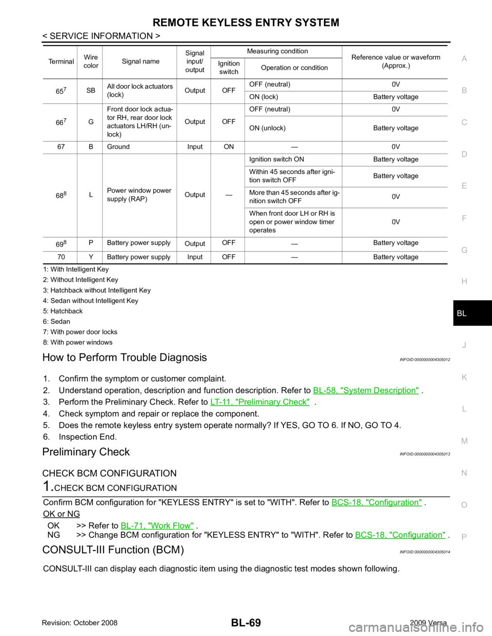
How to Perform Trouble Diagnosis INFOID:0000000004305012
1. Confirm the symptom or customer complaint.
2. Understand operation, description and function description. Refer to BL-58, " System Description " .
3. Perform the Preliminary Check. Refer to LT-11, " Preliminary Check " .
4. Check symptom and repair or replace the component.
5. Does the remote keyless entry system operate normally? If YES, GO TO 6. If NO, GO TO 4.
6. Inspection End.
Preliminary Check INFOID:0000000004305013
CHECK BCM CONFIGURATION Configuration " .
OK or NG OK >> Refer to
BL-71, " Work Flow " .
NG >> Change BCM configuration for "KEYLESS ENTRY" to "WITH". Refer to BCS-18, " Configuration " .
CONSULT-III Function (BCM) INFOID:0000000004305014
CONSULT-III can display each diagnostic item using the diagnostic test modes shown following. 65
7
SBAll door lock actuators
(lock) Output OFFOFF (neutral) 0V
ON (lock) Battery voltage
66 7
GFront door lock actua-
tor RH, rear door lock
actuators LH/RH (un-
lock) Output OFFOFF (neutral) 0V
ON (unlock) Battery voltage
67 B Ground Input ON — 0V
68 8
LPower window power
supply (RAP) Output —Ignition switch ON Battery voltage
Within 45 seconds after igni-
tion switch OFF Battery voltage
More than 45 seconds after ig-
nition switch OFF 0V
When front door LH or RH is
open or power window timer
operates 0V
69 8
P Battery power supply
OutputOFF
— Battery voltage
70 Y Battery power supply Input OFF — Battery voltage
Terminal
Wire
color Signal name Signal
input/
output Measuring condition
Reference value or waveform
(Approx.)
Ignition
switch Operation or condition
Page 532 of 4331
BL
N
O P
Active Test
Work Flow INFOID:0000000004305015
1. Check the symptom and customer's requests.
2. Understand outline of system. Refer to BL-58, " System Description " .
3. Confirm that power door lock system operates normally. Refer to BL-22 .
4. Repair or replace any malfunctioning parts. Refer to BL-71, " Trouble Diagnosis Symptom Chart " .
5. Does remote keyless entry system operate normally? If Yes, GO TO 6. If No, GO TO 4.
6. INSPECTION END
Trouble Diagnosis Symptom Chart INFOID:0000000004305016
NOTE:
• Always check the “Work Flow” before troubleshooting. Refer to BL-71, " Work Flow " .
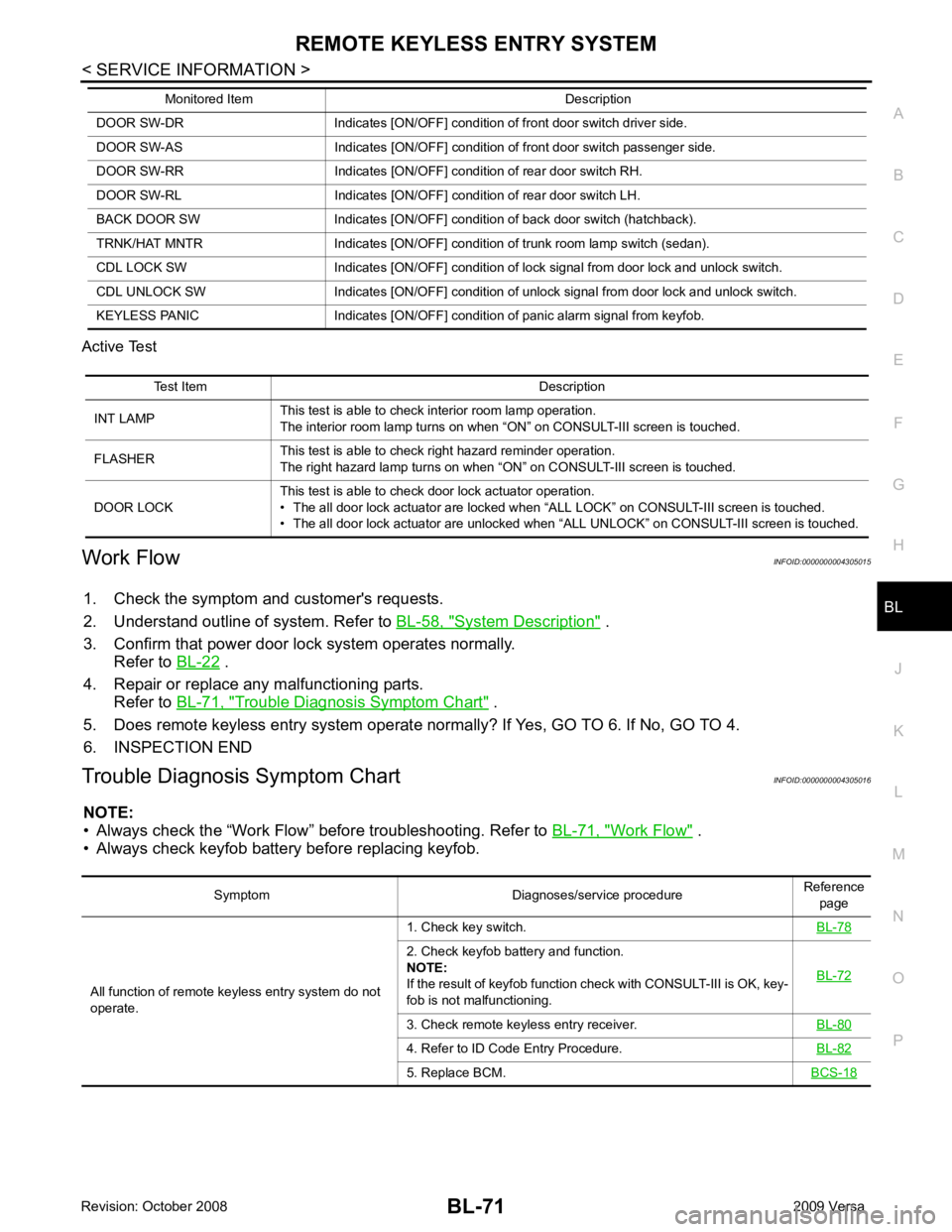
• Always check keyfob battery before replacing keyfob. DOOR SW-DR Indicates [ON/OFF] condition of front door switch driver side.
DOOR SW-AS Indicates [ON/OFF] condition of front door switch passenger side.
DOOR SW-RR Indicates [ON/OFF] condition of rear door switch RH.
DOOR SW-RL Indicates [ON/OFF] condition of rear door switch LH.
BACK DOOR SW Indicates [ON/OFF] condition of back door switch (hatchback).
TRNK/HAT MNTR Indicates [ON/OFF] condition of trunk room lamp switch (sedan).
CDL LOCK SW Indicates [ON/OFF] condition of lock signal from door lock and unlock switch.
CDL UNLOCK SW Indicates [ON/OFF] condition of unlock signal from door lock and unlock switch.
KEYLESS PANIC Indicates [ON/OFF] condition of panic alarm signal from keyfob.
Monitored Item Description Test Item Description
INT LAMP This test is able to check interior room lamp operation.
The interior room lamp turns on when “ON” on CONSULT-III screen is touched.
FLASHER This test is able to check right hazard reminder operation.
The right hazard lamp turns on when “ON” on CONSULT-III screen is touched.
DOOR LOCK This test is able to check door lock actuator operation.
• The all door lock actuator are locked when “ALL LOCK” on CONSULT-III screen is touched.
• The all door lock actuator are unlocked when “ALL UNLOCK” on CONSULT-III screen is touched. Symptom Diagnoses/service procedure
Reference
page
All function of remote keyless entry system do not
operate. 1. Check key switch.
BL-782. Check keyfob battery and function.
NOTE:
If the result of keyfob function check with CONSULT-III is OK, key-
fob is not malfunctioning. BL-723. Check remote keyless entry receiver.
BL-804. Refer to ID Code Entry Procedure.
BL-825. Replace BCM.
BCS-18