Page 200 of 4331

AT
N
O P
Is any malfunction detected by self-diagnostic results? YES >> Check the malfuncti
oning system. Refer to AT-79, " CONSULT-III Functi
on (TRANSMISSION) " or
AT-83, " Diagnosis Procedure without CONSULT-III " .
NO >> GO TO 2. Description " (HR16DE),
EC-959, " Component
Description " (MR Type 1) or
EC-1481, " Component Description " (MR Type 2).
OK or NG OK >> GO TO 3.
NG >> Repair or replace accelerator pedal position sensor. Control Valve Assembly and Accumulators " .
2. Check following items:
- Torque converter clutch control valve
- Torque converter clutch solenoid valve
- Torque converter relief valve
- Pilot valve
- Pilot filter
3. Disassemble A/T. Refer to AT-256, " Disassembly " .
4. Check the following items:
- Torque converter. Refer to AT-256, " Disassembly " .
OK or NG OK >> GO TO 4.
NG >> Repair or replace damaged parts. Cruise Test - Part 1 " .
OK or NG OK >>
INSPECTION END
NG >> GO TO 5. TCM Terminal and Reference Value " .
2. If NG, recheck TCM pin terminals for dam age or loose connection with harness connector.
OK or NG OK >>
INSPECTION END
NG >> Repair or replace damaged parts.
A/T Does Not Hold Lock-up Condition INFOID:0000000004305484
SYMPTOM: A/T does not hold lock-up condition for more than 30 second s on “Cruise Test — Part 1”.
DIAGNOSTIC PROCEDURE CONSULT-III Functi
on (TRANSMISSION) " or
AT-83, " Diagnosis Pro-
cedure without CONSULT-III " .
Is any malfunction detected by self-diagnostic results? YES >> Check the malfuncti
oning system. Refer to AT-79, " CONSULT-III Functi
on (TRANSMISSION) " or
AT-83, " Diagnosis Procedure without CONSULT-III " .
NO >> GO TO 2. Component " .
2. Check A/T fluid condition. Refer to AT-51, " Inspections Before Trouble Diagnosis " .
Page 202 of 4331

AT
N
O P
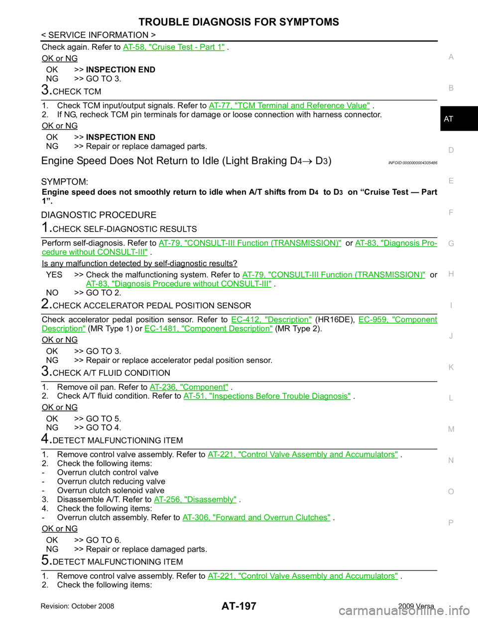
Check again. Refer to
AT-58, " Cruise Test - Part 1 " .
OK or NG OK >>
INSPECTION END
NG >> GO TO 3. TCM Terminal and Reference Value " .
2. If NG, recheck TCM pin terminals for dam age or loose connection with harness connector.
OK or NG OK >>
INSPECTION END
NG >> Repair or replace damaged parts.
Engine Speed Does Not Return to Idle (Light Braking D4→ D 3) INFOID:0000000004305486
SYMPTOM: Engine speed does not smoothly return to idle when A/T shifts from D4 to D 3 on “Cruise Test — Part
1”.
DIAGNOSTIC PROCEDURE CONSULT-III Functi
on (TRANSMISSION) " or
AT-83, " Diagnosis Pro-
cedure without CONSULT-III " .
Is any malfunction detected by self-diagnostic results? YES >> Check the malfuncti
oning system. Refer to AT-79, " CONSULT-III Functi
on (TRANSMISSION) " or
AT-83, " Diagnosis Procedure without CONSULT-III " .
NO >> GO TO 2. Description " (HR16DE),
EC-959, " Component
Description " (MR Type 1) or
EC-1481, " Component Description " (MR Type 2).
OK or NG OK >> GO TO 3.
NG >> Repair or replace accelerator pedal position sensor. Component " .
2. Check A/T fluid condition. Refer to AT-51, " Inspections Before Trouble Diagnosis " .
OK or NG OK >> GO TO 5.
NG >> GO TO 4. Control Valve Assembly and Accumulators " .
2. Check the following items:
- Overrun clutch control valve
- Overrun clutch reducing valve
- Overrun clutch solenoid valve
3. Disassemble A/T. Refer to AT-256, " Disassembly " .
4. Check the following items:
- Overrun clutch assembly. Refer to AT-306, " Forward and Overrun Clutches " .
OK or NG OK >> GO TO 6.
NG >> Repair or replace damaged parts. Control Valve Assembly and Accumulators " .
2. Check the following items:
Page 206 of 4331

TROUBLE DIAGNOSIS FOR SYMPTOMS
AT-201
< SERVICE INFORMATION >
D
E
F
G H
I
J
K L
M A
B AT
N
O P
OK >> GO TO 3
NG >> Check PNP switch. Refer to AT-176, " Component Inspection " .
2.
CHECK PNP SWITCH CIRCUIT
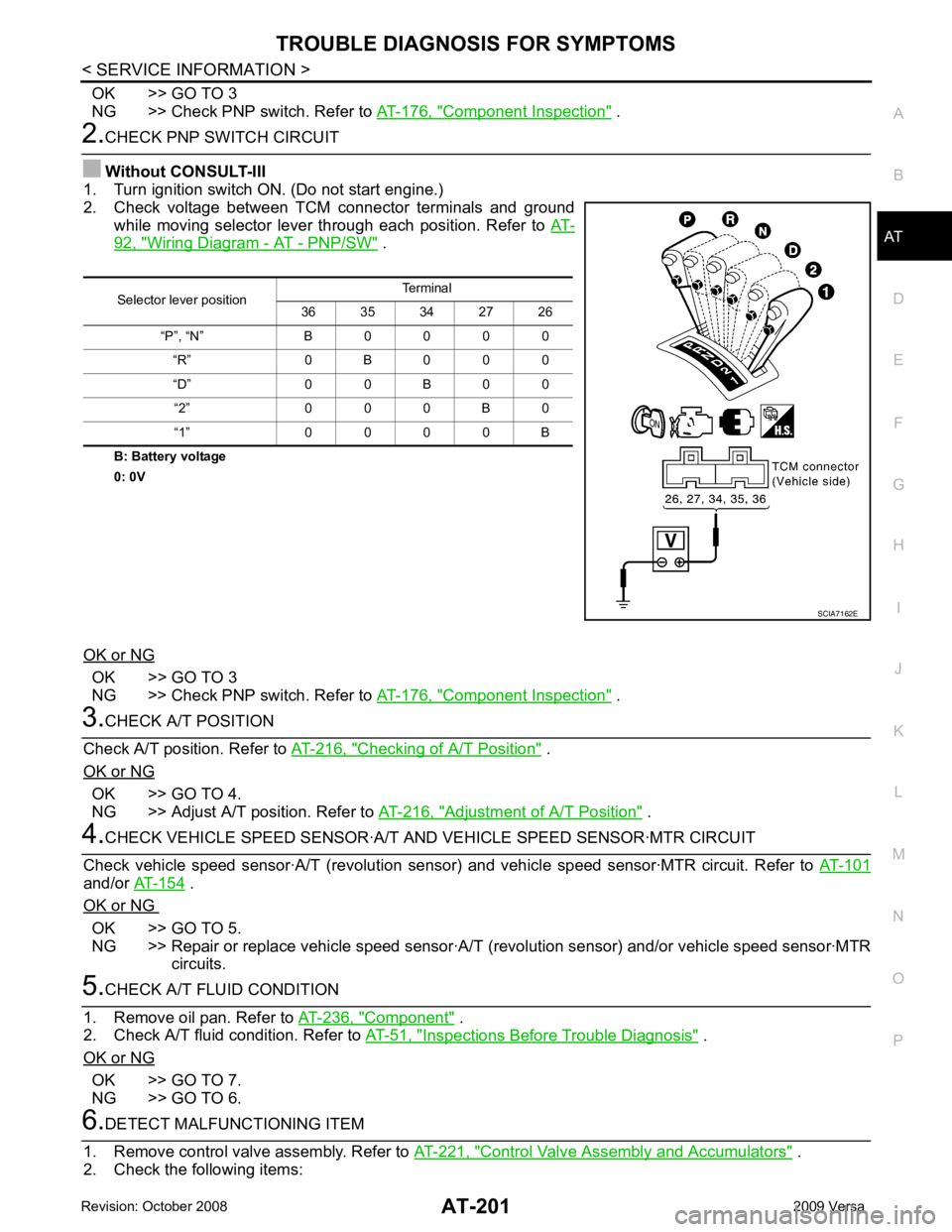
Without CONSULT-III
1. Turn ignition switch ON. (Do not start engine.)
2. Check voltage between TCM connector terminals and ground
while moving selector lever through each position. Refer to AT-92, " Wiring Diagram - AT - PNP/SW " .
B: Battery voltage
0: 0V
OK or NG OK >> GO TO 3
NG >> Check PNP switch. Refer to AT-176, " Component Inspection " .
3.
CHECK A/T POSITION
Check A/T position. Refer to AT-216, " Checking of A/T Position " .
OK or NG OK >> GO TO 4.
NG >> Adjust A/T position. Refer to AT-216, " Adjustment of A/T Position " .
4.
CHECK VEHICLE SPEED SENS OR·A/T AND VEHICLE SPEED SENSOR·MTR CIRCUIT
Check vehicle speed sensor·A/T (re volution sensor) and vehicle speed sensor·MTR circuit. Refer to AT-101and/or
AT-154 .
OK or NG OK >> GO TO 5.
NG >> Repair or replace vehicle speed sensor·A/T (revolution sensor) and/or vehicle speed sensor·MTR
circuits. 5.
CHECK A/T FLUID CONDITION
1. Remove oil pan. Refer to AT-236, " Component " .
2. Check A/T fluid condition. Refer to AT-51, " Inspections Before Trouble Diagnosis " .
OK or NG OK >> GO TO 7.
NG >> GO TO 6. 6.
DETECT MALFUNCTIONING ITEM
1. Remove control valve assembly. Refer to AT-221, " Control Valve Assembly and Accumulators " .
2. Check the following items: Selector lever position
Terminal
36 35 34 27 26
“P”, “N” B 0 0 0 0 “R” 0 B 0 0 0
“D” 0 0 B 0 0 “2” 0 0 0 B 0
“1” 0 0 0 0 B SCIA7162E
Page 209 of 4331

AT-204< SERVICE INFORMATION >
TROUBLE DIAGNOSIS FOR SYMPTOMS
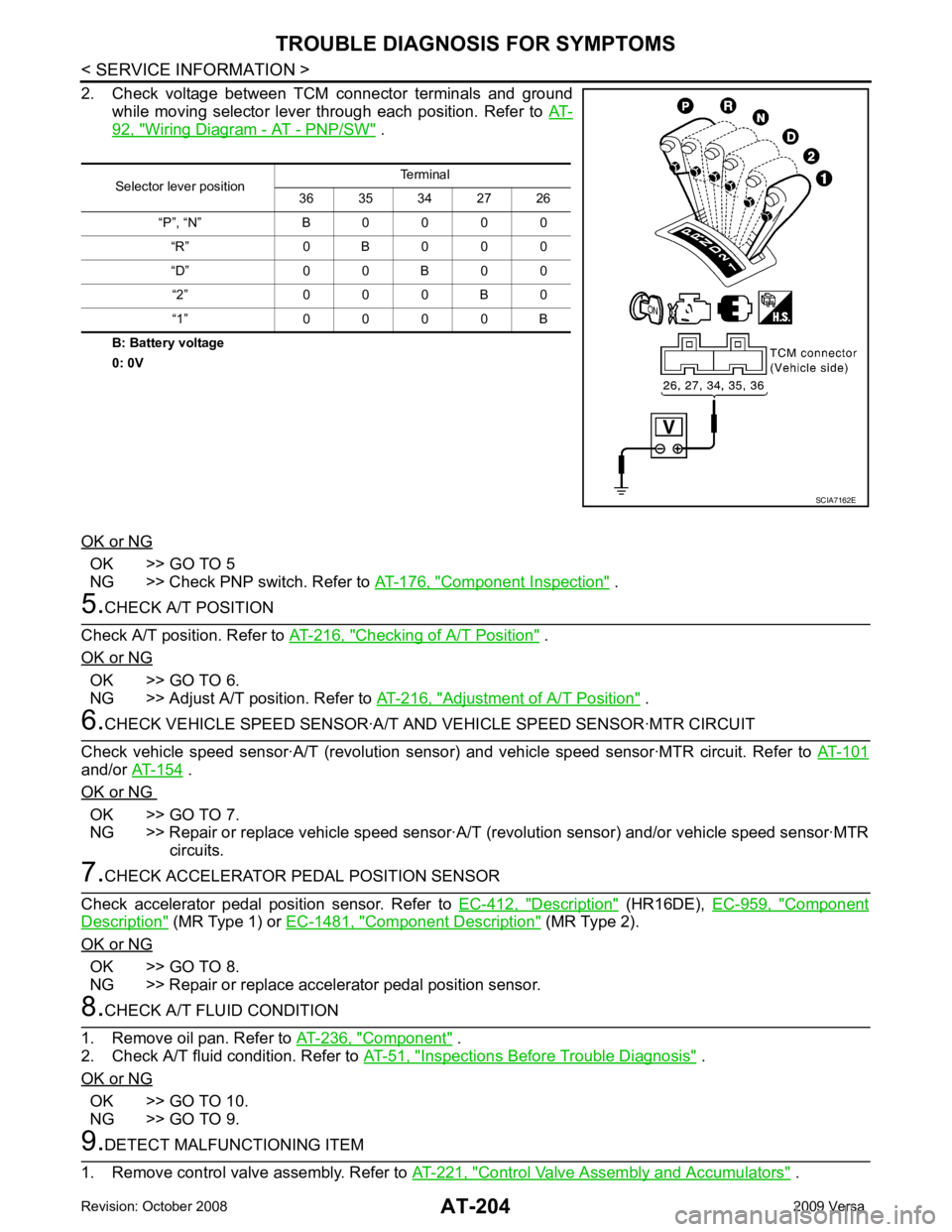
2. Check voltage between TCM connector terminals and ground while moving selector lever through each position. Refer to AT-92, " Wiring Diagram - AT - PNP/SW " .
B: Battery voltage
0: 0V
OK or NG OK >> GO TO 5
NG >> Check PNP switch. Refer to AT-176, " Component Inspection " .
5.
CHECK A/T POSITION
Check A/T position. Refer to AT-216, " Checking of A/T Position " .
OK or NG OK >> GO TO 6.
NG >> Adjust A/T position. Refer to AT-216, " Adjustment of A/T Position " .
6.
CHECK VEHICLE SPEED SENSOR·A/T A ND VEHICLE SPEED SENSOR·MTR CIRCUIT
Check vehicle speed sensor·A/T (revolution senso r) and vehicle speed sensor·MTR circuit. Refer to AT-101and/or
AT-154 .
OK or NG OK >> GO TO 7.
NG >> Repair or replace vehicle speed sensor·A/T (revolution sensor) and/or vehicle speed sensor·MTR
circuits. 7.
CHECK ACCELERATOR PEDAL POSITION SENSOR
Check accelerator pedal position sensor. Refer to EC-412, " Description " (HR16DE),
EC-959, " Component
Description " (MR Type 1) or
EC-1481, " Component Description " (MR Type 2).
OK or NG OK >> GO TO 8.
NG >> Repair or replace accelerator pedal position sensor. 8.
CHECK A/T FLUID CONDITION
1. Remove oil pan. Refer to AT-236, " Component " .
2. Check A/T fluid condition. Refer to AT-51, " Inspections Before Trouble Diagnosis " .
OK or NG OK >> GO TO 10.
NG >> GO TO 9. 9.
DETECT MALFUNCTIONING ITEM
1. Remove control valve assembly. Refer to AT-221, " Control Valve Assembly and Accumulators " .
Selector lever position
Terminal
36 35 34 27 26
“P”, “N” B 0 0 0 0 “R” 0 B 0 0 0
“D” 0 0 B 0 0 “2” 0 0 0 B 0
“1” 0 0 0 0 B SCIA7162E
Page 215 of 4331
.
OK or NG OK >> GO TO 6.
NG >> Repair or replace damaged parts. .
OK or NG OK >>
INSPECTION END
NG >> Repair or replace damaged parts. OK >> Replace shift lock solenoid and park position switch
assembly.
NG >> Repair open circuit or short to ground or short to power in harness or connectors.Condition Continuity
When brake pedal is depressed Yes
When brake pedal is released No
Page 433 of 4331

AV
N
O P
Bluetooth Control Unit
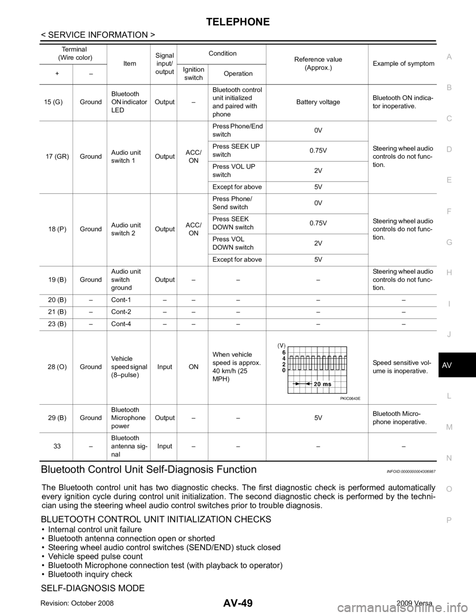
Self-Diagnosis Function INFOID:0000000004306987
The Bluetooth control unit has two diagnostic checks. The first diagnostic check is performed automatically
every ignition cycle during control unit initialization. The second diagnostic check is performed by the techni-
cian using the steering wheel audio control switches prior to trouble diagnosis.
BLUETOOTH CONTROL UNIT INITIALIZATION CHECKS
• Internal control unit failure
• Bluetooth antenna connection open or shorted
• Steering wheel audio control swit ches (SEND/END) stuck closed
• Vehicle speed pulse count
• Bluetooth Microphone connection test (with playback to operator)
• Bluetooth inquiry check
SELF-DIAGNOSIS MODE 15 (G) Ground
Bluetooth
ON indicator
LED Output – Bluetooth control
unit initialized
and paired with
phone Battery voltage
Bluetooth ON indica-
tor inoperative.
17 (GR) Ground Audio unit
switch 1 OutputACC/
ON Press Phone/End
switch 0V
Steering wheel audio
controls do not func-
tion.
Press SEEK UP
switch 0.75V
Press VOL UP
switch 2V
Except for above 5V
18 (P) Ground Audio unit
switch 2 OutputACC/
ON Press Phone/
Send switch 0V
Steering wheel audio
controls do not func-
tion.
Press SEEK
DOWN switch 0.75V
Press VOL
DOWN switch 2V
Except for above 5V
19 (B) Ground Audio unit
switch
ground Output – – – Steering wheel audio
controls do not func-
tion.
20 (B) – Cont-1 – – – – –
21 (B) – Cont-2 – – – – –
23 (B) – Cont-4 – – – – –
28 (O) Ground Vehicle
speed signal
(8–pulse) Input ON When vehicle
speed is approx.
40 km/h (25
MPH) Speed sensitive vol-
ume is inoperative.
29 (B) Ground Bluetooth
Microphone
power Output – – 5V
Bluetooth Micro-
phone inoperative.
33 – Bluetooth
antenna sig-
nal Input – – – –
Terminal
(Wire color) ItemSignal
input/
output Condition
Reference value
(Approx.) Example of symptom
+ – Ignition
switch Operation
Page 437 of 4331
AV
N
O P OK >> Repair or replace harness.
NG >> Replace Bluetooth control unit. AV-55, " Removal and
Installation " .
Voice Activated Control F unction Does Not Operate INFOID:0000000004306992
NOTE:
Even under the normal condition, Bluetooth voice guidance may not occur when pressing steering wheel
audio control switch.
BLUETOOTH VOICE GUIDANCE IS HEARD WHEN PRESSING STEERING WHEEL AUDIO CON-
TROL SWITCH OK >> GO TO 2.
NG >> Repair harness or connector.
Page 458 of 4331
OK >> GO TO 3.
NG >> Repair or replace the harness. OK >> Power supply and ground circuit is OK.
NG >> Repair or replace harness.
CONSULT-III Function (BCM) INFOID:0000000004306839
CONSULT-III can display each diagnostic item us ing the diagnostic test modes shown following.
ITEMS OF EACH PART
NOTE:
CONSULT-III will only display systems the vehicle possesses. M20
57 Ground
Battery
power
supply Ignition
switch
OFF Battery voltage
70 Ground Battery
power
supply Ignition
switch OFF Battery voltage
Connector
Terminals
Power
source Condition Voltage (V) (Ap-
prox.)
(+) (-) System and item
CONSULT-III dis-
play Diagnostic test mode (Inspection by part)
WORK
SUPPORT SELF
−
DIAG RE- SULTS CAN DIAG
SUPPORT MNTR DATA
MONITOR ECU
PART
NUMBER AC-
TIVE
TEST CON-
FIGU-
RATION
BCM BCM × × × × ×
Power door lock sys-
tem DOOR LOCK
× × ×
Rear defogger REAR DEFOG-
GER × ×
Warning chime BUZZER × ×