2009 NISSAN LATIO air condition
[x] Cancel search: air conditionPage 706 of 4331

BL
N
O P
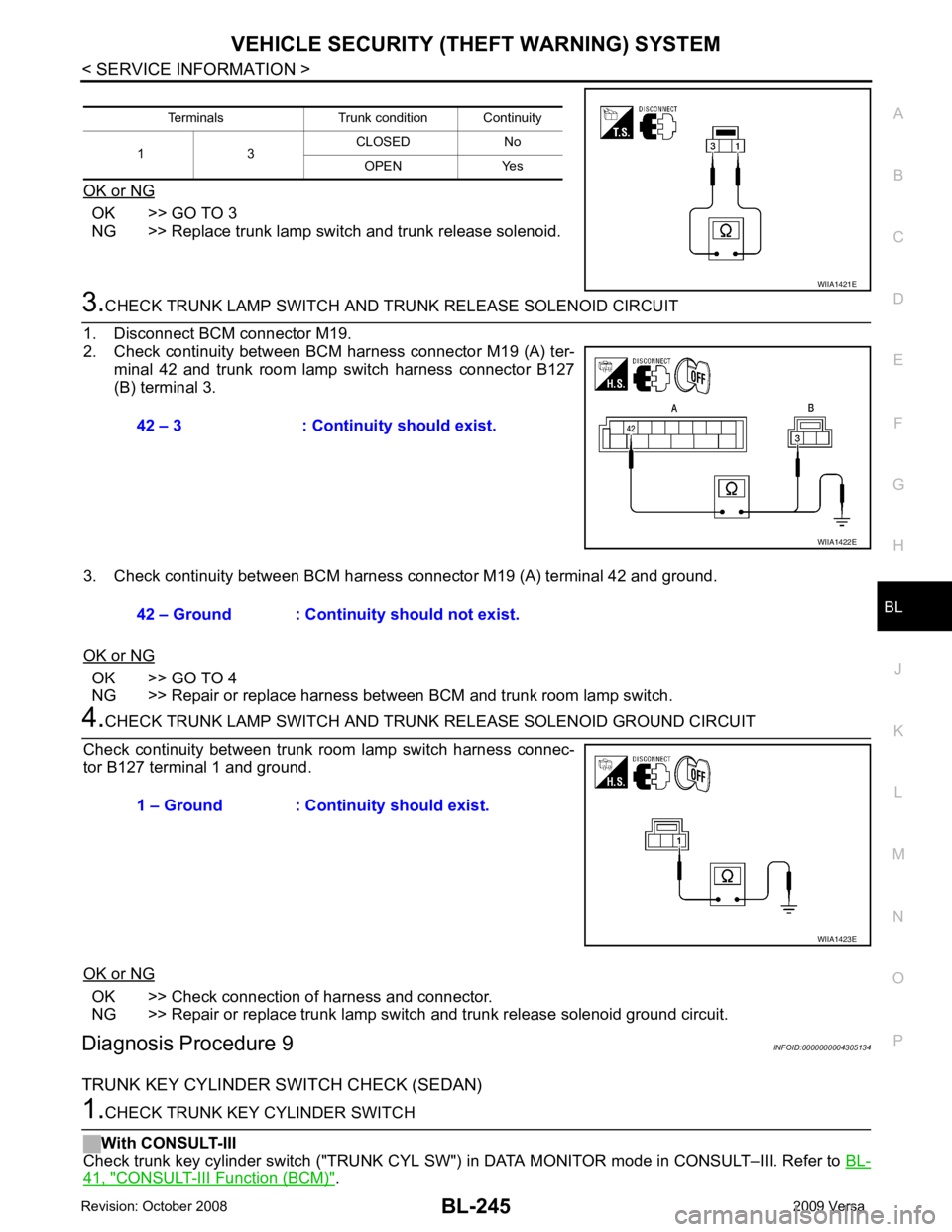
OK or NG OK >> GO TO 3
NG >> Replace trunk lamp switch and trunk release solenoid. OK >> GO TO 4
NG >> Repair or replace harness between BCM and trunk room lamp switch. OK >> Check connection of harness and connector.
NG >> Repair or replace trunk lamp switch and trunk release solenoid ground circuit.
Diagnosis Procedure 9 INFOID:0000000004305134
TRUNK KEY CYLINDER SWITCH CHECK (SEDAN) 41, " CONSULT-III Function (BCM) " .
Terminals Trunk condition Continuity
1 3 CLOSED No
OPEN Yes
Page 843 of 4331

BRC
N
O P
Precaution for Brake Control
INFOID:0000000004307252
• During ABS operation, the brake pedal may vibrate lightly and a mechanical noise may be heard. This is normal.
• Just after starting the vehicle, the brake pedal may vibrate or motor operating noises may be heard from
engine compartment. This is normal due to the self check operation.
• Stopping distance may be longer than that of vehicles without ABS when vehicle drives on rough, gravel, or
snow-covered (fresh, deep snow) roads.
• When an error is indicated by ABS or another warning lamp, collect all necessary information from customer
(what symptoms are present under what conditions) and check for simple causes before starting diagnosis.
Besides electrical system inspection, check brake booster operation, brake fluid level, and fluid leaks.
• If incorrect tire sizes or types are installed on the vehicle or brake pads are not Genuine NISSAN parts, stop-
ping distance or steering stability may deteriorate.
• If there is a radio, antenna or related wiring near t he control module, ABS function may have a malfunction
or error.
• If aftermarket parts (car stereo, CD player, etc.) have been installed, check for incidents such as harness pinches, open circuits or improper wiring.
Precaution for CAN System INFOID:0000000004307253
• Do not apply voltage of 7.0V or higher to terminal to be measured.
• Maximum open terminal voltage of tester in use must be less than 7.0V.
• Before checking harnesses, turn ignition switch OFF and disconnect battery negative cable.
• Area to be repaired must be soldered and wrapped with tape. Make sure that fraying of twisted wire is within 110 mm (4.33 in).
• Do not make a bypass connection to repaired area. (If the circuit is bypassed, characteristics of twisted wire will be lost.)
Page 934 of 4331
![NISSAN LATIO 2009 Service Repair Manual CO-40< SERVICE INFORMATION >
[MR18DE]
RADIATOR
Checking Radiator Cap INFOID:0000000004305238
• Check valve seat of radiator cap.
- Check if valve seat is swollen to the extent that the e NISSAN LATIO 2009 Service Repair Manual CO-40< SERVICE INFORMATION >
[MR18DE]
RADIATOR
Checking Radiator Cap INFOID:0000000004305238
• Check valve seat of radiator cap.
- Check if valve seat is swollen to the extent that the e](/manual-img/5/57359/w960_57359-933.png)
CO-40< SERVICE INFORMATION >
[MR18DE]
RADIATOR
Checking Radiator Cap INFOID:0000000004305238
• Check valve seat of radiator cap.
- Check if valve seat is swollen to the extent that the edge of the plunger cannot be seen when watching it vertically from the top.
- Check if valve seat has no soil and damage.
• Pull negative-pressure valve to open it, and make sure that it is completely closed when released.
- Make sure that there is no dirt or damage on the valve seat of radi-
ator cap negative-pressure valve.
- Make sure that the valve operates properly in the opening and closing conditions.
• Check radiator cap relief pressure using Tool.
- When connecting the radiator cap to the tester, apply water or coolant to the cap seal surface.
- Replace the radiator cap if ther e is an abnormality in the negative-
pressure valve, or if the open-valve pr essure is outside of the standard values.
• Replace radiator cap if there it does not comply to specifications to the above three checks.
CAUTION:
When installing radiator cap, thoroughly wipe out the radiator filler neck to remove any waxy residue
or foreign material.
Checking Radiator INFOID:0000000004305239
Check radiator for mud or clogging. If necessary, clean radiator as follows.
• Be careful not to bend or damage radiator fins.
• When radiator is cleaned without removal, remove all surrounding parts such as cooling fan, radiator shroud and horns. Then tape harness and connectors to prevent water from entering.
1. Apply water by hose to the back side of the radiator core vertically downward.
2. Apply water again to all radiator core surface once per minute.
3. Stop washing if any stains no longer flow out from radiator.
4. Blow air into the back side of radiator core vertically downward. • Use compressed air lower than 490 kPa (4.9 bar, 5 kg/cm 2
, 71 psi) and keep distance more than 30 cm
(11.8 in).
5. Blow air again into all the radiator core surfaces once per minute until no water sprays out. PBIC2816E
SMA967B
Tool number : EG17650301 (J-33984-A)
Standard: 78 – 98 kPa (0.78 - 0.98 bar, 0.8 – 1.0 kg/cm 2
, 11
– 14 psi)
Limit: 59 kPa (0.59 bar, 0.6 kg/cm 2
, 9 psi) WBIA0570E
Page 975 of 4331

CVT
N
O P
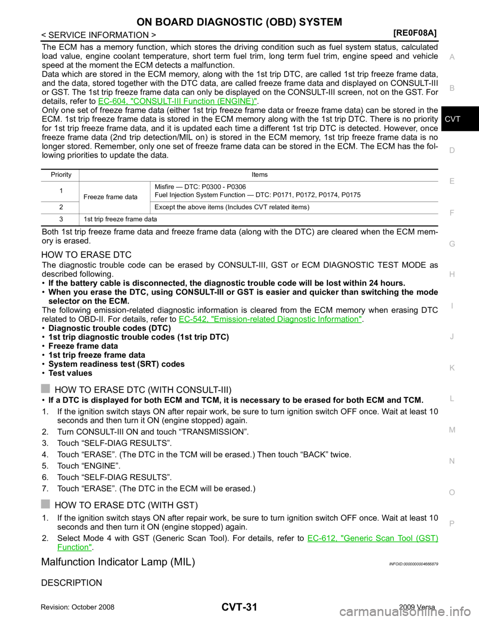
The ECM has a memory function, which stores the driv
ing condition such as fuel system status, calculated
load value, engine coolant temperature, short term f uel trim, long term fuel trim, engine speed and vehicle
speed at the moment the ECM detects a malfunction.
Data which are stored in the ECM memory, along with the 1st trip DTC, are called 1st trip freeze frame data,
and the data, stored together with the DTC data, are called freeze frame data and displayed on CONSULT-III
or GST. The 1st trip freeze frame data can only be di splayed on the CONSULT-III screen, not on the GST. For
details, refer to EC-604, " CONSULT-III Function (ENGINE) " .
Only one set of freeze frame data (either 1st trip freez e frame data or freeze frame data) can be stored in the
ECM. 1st trip freeze frame data is stored in the ECM me mory along with the 1st trip DTC. There is no priority
for 1st trip freeze frame data, and it is updated each time a different 1st trip DTC is detected. However, once
freeze frame data (2nd trip detection/MIL on) is stored in the ECM memory, 1st trip freeze frame data is no
longer stored. Remember, only one set of freeze frame data can be stored in the ECM. The ECM has the fol-
lowing priorities to update the data.
Both 1st trip freeze frame data and freeze frame data (along with the DTC) are cleared when the ECM mem-
ory is erased.
HOW TO ERASE DTC The diagnostic trouble code can be erased by CONSULT- III, GST or ECM DIAGNOSTIC TEST MODE as
described following.
• If the battery cable is disconnected, the diagnost ic trouble code will be lost within 24 hours.
• When you erase the DTC, using CONSULT-III or GS T is easier and quicker than switching the mode
selector on the ECM.
The following emission-related diagnostic information is cleared from the ECM memory when erasing DTC
related to OBD-II. For details, refer to EC-542, " Emission-related Diagnostic Information " .
• Diagnostic trouble codes (DTC)
• 1st trip diagnostic trouble codes (1st trip DTC)
• Freeze frame data
• 1st trip freeze frame data
• System readiness test (SRT) codes
• Test values
HOW TO ERASE DTC (WITH CONSULT-III)
• If a DTC is displayed for both ECM and TCM, it is necessary to be erased for both ECM and TCM.
1. If the ignition switch stays ON after repair work, be su re to turn ignition switch OFF once. Wait at least 10
seconds and then turn it ON (engine stopped) again.
2. Turn CONSULT-III ON and touch “TRANSMISSION”.
3. Touch “SELF-DIAG RESULTS”.
4. Touch “ERASE”. (The DTC in the TCM will be erased.) Then touch “BACK” twice.
5. Touch “ENGINE”.
6. Touch “SELF-DIAG RESULTS”.
7. Touch “ERASE”. (The DTC in the ECM will be erased.)
HOW TO ERASE DTC (WITH GST)
1. If the ignition switch stays ON after repair work, be su re to turn ignition switch OFF once. Wait at least 10
seconds and then turn it ON (engine stopped) again.
2. Select Mode 4 with GST (Generic Scan Tool). For details, refer to EC-612, " Generic Scan Tool (GST)
Function " .
Malfunction Indicator Lamp (MIL) INFOID:0000000004666879
DESCRIPTION Priority Items
1 Freeze frame data Misfire — DTC: P0300 - P0306
Fuel Injection System Function — DTC: P0171, P0172, P0174, P0175
2 Except the above items (Includes CVT related items)
3 1st trip freeze frame data
Page 978 of 4331
![NISSAN LATIO 2009 Service Repair Manual CVT-34< SERVICE INFORMATION >
[RE0F08A]
TROUBLE DIAGNOSIS
If an unexpected signal is sent from the solenoid to t he TCM, the CVT lock-up select solenoid is turned OFF to
cancel the lock-up.
TCM Power NISSAN LATIO 2009 Service Repair Manual CVT-34< SERVICE INFORMATION >
[RE0F08A]
TROUBLE DIAGNOSIS
If an unexpected signal is sent from the solenoid to t he TCM, the CVT lock-up select solenoid is turned OFF to
cancel the lock-up.
TCM Power](/manual-img/5/57359/w960_57359-977.png)
CVT-34< SERVICE INFORMATION >
[RE0F08A]
TROUBLE DIAGNOSIS
If an unexpected signal is sent from the solenoid to t he TCM, the CVT lock-up select solenoid is turned OFF to
cancel the lock-up.
TCM Power Supply (Memory Back-up)
Transaxle assembly is protected by limiting the engine torque when the memory back-up power supply (for
controlling) from the battery is not supplied to TCM. Normal statues is restored when turning the ignition switch
OFF to ON after the normal power supply.
How to Perform Trouble Diagnosis for Quick and Accurate Repair INFOID:0000000004666882
INTRODUCTION
The TCM receives a signal from the vehicle speed sensor, PNP switch and provides shift control or lock-up
control via CVT solenoid valves.
The TCM also communicates with the ECM by means of a signal
sent from sensing elements used wit h the OBD-related parts of the
CVT system for malfunction-diagnostic purposes. The TCM is capa-
ble of diagnosing malfunctioning parts while the ECM can store mal-
functions in its memory.
Input and output signals must always be correct and stable in the
operation of the CVT system. The CVT system must be in good
operating condition and be free of valve seizure, solenoid valve mal-
function, etc.
It is much more difficult to diagnose an error that occurs intermit-
tently rather than continuously. Mo st intermittent errors are caused
by poor electric connections or improper wiring. In this case, careful
checking of suspected circuits ma y help prevent the replacement of
good parts.
A visual check only may not find the cause of the errors. A road test
with CONSULT-III (or GST) or a circuit tester connected should be
performed. Follow the "WORK FLOW" .
Before undertaking actual checks, take a few minutes to talk with a
customer who approaches with a driveability complaint. The cus-
tomer can supply good information about such errors, especially
intermittent ones. Find out what symptoms are present and under
what conditions they occur. A “DIAGNOSTIC WORKSHEET” as
shown on the example (Refer to "Diagnostic Worksheet Chart" )
should be used.
Start your diagnosis by looking for “conventional” errors first. This will
help troubleshoot driveability errors on an electronically controlled
engine vehicle.
Also check related Service bulletins.
WORK FLOW
A good understanding of the malfunction conditions can make troubleshooting faster and more accurate.
In general, each customer feels differently about a malf unction. It is important to fully understand the symp-
toms or conditions for a customer complaint.
Make good use of the two sheets provided, "Informati on From Customer" and "Diagnostic Worksheet Chart" ,
to perform the best troubleshooting possible.
Work Flow Chart SAT631IB
SAT632I
SEF234G
Page 993 of 4331
![NISSAN LATIO 2009 Service Repair Manual TROUBLE DIAGNOSIS
CVT-49
< SERVICE INFORMATION >
[RE0F08A] D
E
F
G H
I
J
K L
M A
B CVT
N
O P 9.
CHECK ENGINE BRAKE FUNCTION — PART 3
1. Move selector lever to “L” position.
2. Check engine brake NISSAN LATIO 2009 Service Repair Manual TROUBLE DIAGNOSIS
CVT-49
< SERVICE INFORMATION >
[RE0F08A] D
E
F
G H
I
J
K L
M A
B CVT
N
O P 9.
CHECK ENGINE BRAKE FUNCTION — PART 3
1. Move selector lever to “L” position.
2. Check engine brake](/manual-img/5/57359/w960_57359-992.png)
TROUBLE DIAGNOSIS
CVT-49
< SERVICE INFORMATION >
[RE0F08A] D
E
F
G H
I
J
K L
M A
B CVT
N
O P 9.
CHECK ENGINE BRAKE FUNCTION — PART 3
1. Move selector lever to “L” position.
2. Check engine brake.
Does engine braking effectively reduce speed in “ L ” position?
YES >> 1. Stop the vehicle.
2. Perform self-diagnosis. Refer to CVT-51, " CONSULT-III Function (TRANSMISSION) " .
NO >> Mark the box of CVT-163, " Vehicle Does Not Decelerate by Engine Brake " on the
CVT-34, " How
to Perform Trouble Diagnosis for Quick and Accurate Repair " . Then continue trouble diagnosis.
Vehicle Speed When Shifting Gears INFOID:0000000004666890
Numerical value data are reference values.
CAUTION:
Lock-up clutch is engaged when vehi cle speed is approximately 18 km/h (11 MPH) to 90 km/h (56 MPH).
TCM Terminal and Reference Value INFOID:0000000004666891
TCM HARNESS CONNECTOR TERMINAL LAYOUT
TERMINALS AND REFERENCE VALUES FOR TCM Data are reference values and are measured between each terminal and ground.
Engine type Throttle position Shift pattern
Engine speed (rpm)
At 40 km/h (25 MPH) At 60 km/h (37 MPH)
MR18DE 8/8
“D” position
Overdrive-off mode “L” position 3,600 - 4,500 4,400 - 5,300
2/8 “D” position 1,300 - 3,100 1,400 - 3,500
Overdrive-off mode 2,200 - 3,000 2,800 - 3,600 “L” position 3,200 - 4,100 3,900 - 4,800 WCIA0717E
Terminal
Wire
color Item Condition Data (Approx.)
1 GR Pressure control
solenoid valve A
(Line pressure
solenoid valve)
and Release your foot from the accelerator pedal. 5.0 - 7.0 V
Press the accelerator pedal all the way down. 1.0 - 3.0 V
2 LG Pressure control
solenoid valve B
(Secondary
pressure sole-
noid valve) Release your foot from the accelerator pedal. 5.0 - 7.0 V
Press the accelerator pedal all the way down. 3.0 - 4.0 V
3 SB Torque converter
clutch solenoid
valve When vehi-
cle cruises in
“D” position. When CVT performs lock-up. 6.0 V
When CVT does not perform lock-up. 1.0 V
Page 1010 of 4331

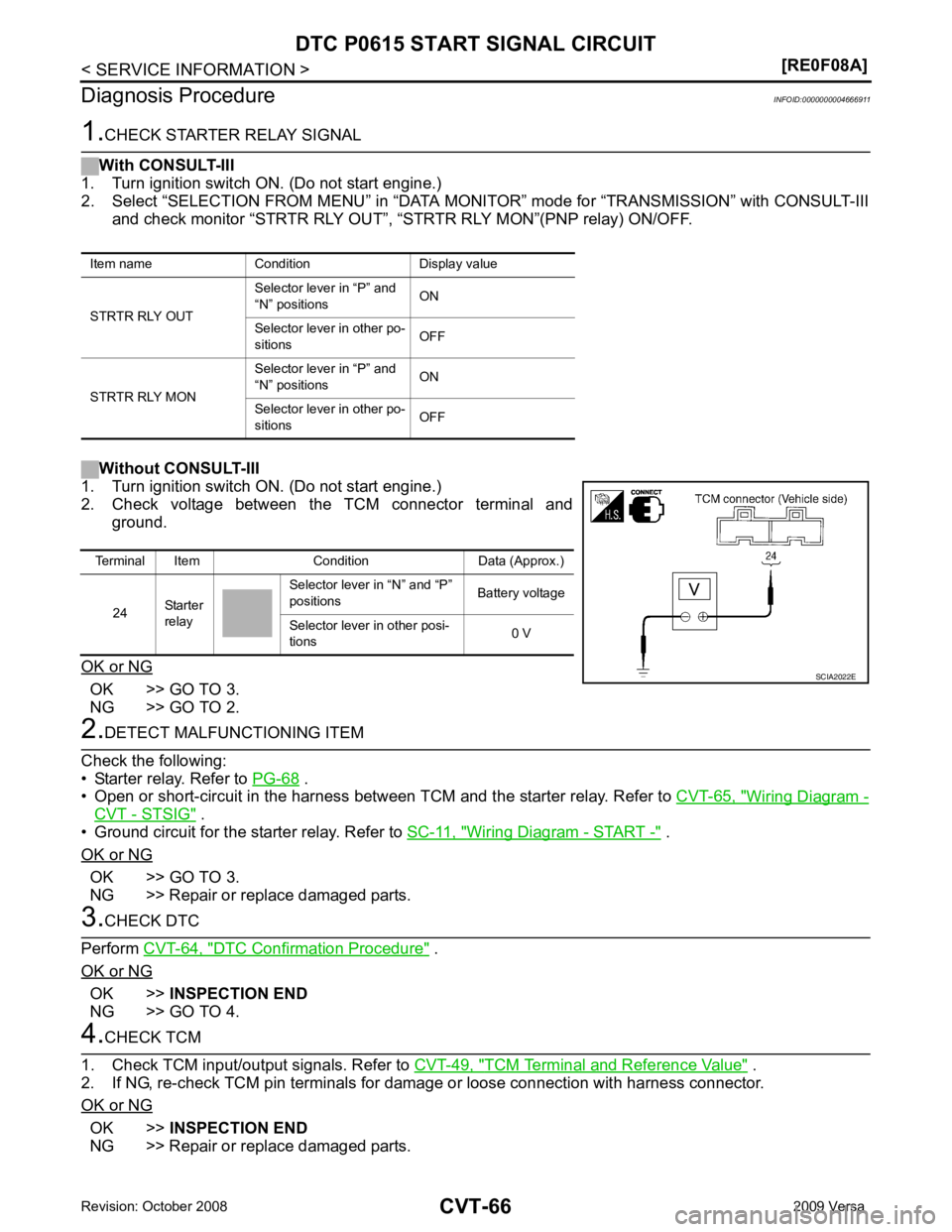
OK >> GO TO 3.
NG >> GO TO 2. .
• Open or short-circuit in the harness between TCM and the starter relay. Refer to CVT-65, " Wiring Diagram -
CVT - STSIG " .
• Ground circuit for the starter relay. Refer to SC-11, " Wiring Diagram - START - " .
OK or NG OK >> GO TO 3.
NG >> Repair or replace damaged parts. DTC Confirmation Procedure " .
OK or NG OK >>
INSPECTION END
NG >> GO TO 4. TCM Terminal and Reference Value " .
2. If NG, re-check TCM pin terminals for damage or loose connection with harness connector.
OK or NG OK >>
INSPECTION END
NG >> Repair or replace damaged parts.
Item name Condition Display value
STRTR RLY OUT Selector lever in “P” and
“N” positions ON
Selector lever in other po-
sitions OFF
STRTR RLY MON Selector lever in “P” and
“N” positions ON
Selector lever in other po-
sitions OFFTerminal Item Condition Data (Approx.)
24 Starter
relay Selector lever in “N” and “P”
positions Battery voltage
Selector lever in other posi-
tions 0 V
Page 1012 of 4331

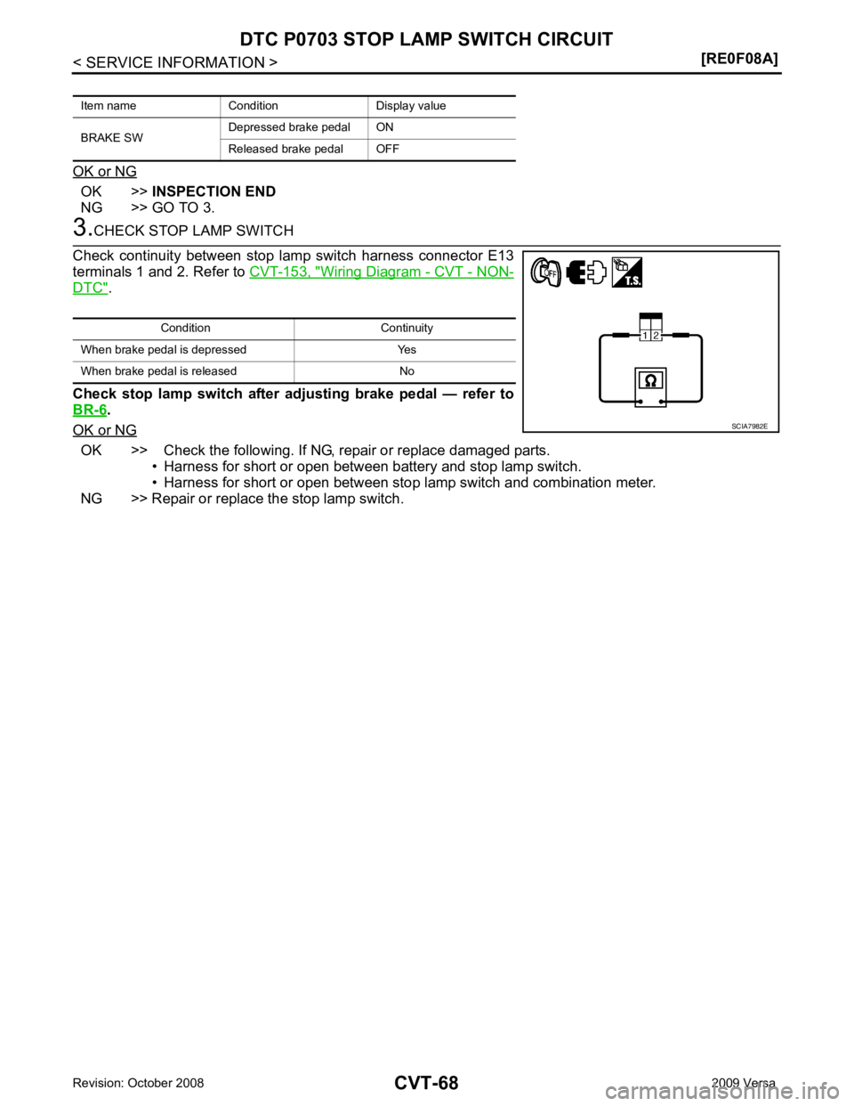
OK >>
INSPECTION END
NG >> GO TO 3. Wiring Diagram - CVT - NON-
DTC " .
Check stop lamp switch after adjusting brake pedal — refer to
BR-6 .
OK or NG OK >> Check the following. If NG, repair or replace damaged parts.
• Harness for short or open between battery and stop lamp switch.
• Harness for short or open between stop lamp switch and combination meter.
NG >> Repair or replace the stop lamp switch.
Item name Condition Display value
BRAKE SW Depressed brake pedal ON
Released brake pedal OFF Condition Continuity
When brake pedal is depressed Yes
When brake pedal is released No