2009 NISSAN LATIO air condition
[x] Cancel search: air conditionPage 1141 of 4331
![NISSAN LATIO 2009 Service Repair Manual CVT FLUID
CVT-197
< SERVICE INFORMATION >
[RE0F08B] D
E
F
G H
I
J
K L
M A
B CVT
N
O P
FLUID CONDITION CHECK
Changing CVT Fluid INFOID:0000000004305571
1. Warm up CVT fluid by driving the vehicle for 1 NISSAN LATIO 2009 Service Repair Manual CVT FLUID
CVT-197
< SERVICE INFORMATION >
[RE0F08B] D
E
F
G H
I
J
K L
M A
B CVT
N
O P
FLUID CONDITION CHECK
Changing CVT Fluid INFOID:0000000004305571
1. Warm up CVT fluid by driving the vehicle for 1](/manual-img/5/57359/w960_57359-1140.png)
CVT FLUID
CVT-197
< SERVICE INFORMATION >
[RE0F08B] D
E
F
G H
I
J
K L
M A
B CVT
N
O P
FLUID CONDITION CHECK
Changing CVT Fluid INFOID:0000000004305571
1. Warm up CVT fluid by driving the vehicle for 10 minutes.
• : Vehicle front
• Radiator (2)
• CVT fluid cooler hose [inlet side (3)]
• Transaxle assembly (4)
2. Drain CVT fluid from CVT fluid cooler hose [outlet side (1)] and refill with new specified NISSAN CVT fluid in the CVT fluid
charging pipe with the engine running at idle speed.
CAUTION:
Only use the specifi ed NISSAN CVT fluid.
3. Refill until new CVT fluid comes out from CVT fluid cooler hose [outlet side (1)]. NOTE:
About 30 to 50% extra fluid will be required for this procedure.
4. Check fluid level and condition. Refer to CVT-196, " Checking CVT Fluid " .
CAUTION:
Delete CVT fluid deterioration date with CO NSULT-III after changing CVT fluid. Refer to CVT-230," CONSULT-III Function (TRANSMISSION) " .
CVT Fluid Cooler Cleaning INFOID:0000000004305572
Whenever a CVT is repaired, overhauled, or replaced, t he CVT fluid cooler mounted in the radiator must be
inspected and cleaned.
Metal debris and friction material, if present, can be trapped or become deposit in the CVT fluid cooler. This
debris can contaminate the newly serviced CVT or, in severe cases, can block or restrict the flow of CVT fluid.
In either case, malfunction of the newly serviced CVT may occur.
Debris, if present, may deposit as CVT fluid enters the cool er inlet. It will be necessary to back flush the cooler
through the cooler outlet in order to flush out any built up debris.
CVT FLUID COOLER CLEANING PROCEDURE 1. Identify the CVT inlet and outlet fluid cooler hoses.
2. Position an oil pan under the inlet and outlet cooler hoses. Fluid status Conceivable cause Required operation
Varnished (viscous
varnish state) Clutch, brake
scorched Replace the CVT fluid and check the
CVT main unit and the vehicle for
malfunctions (wire harness, cooler
pipes, etc.)
Milky white or cloudy Water in the fluid Replace the CVT fluid and check for places where water is getting in.
Large amount of
metal powder mixed
in fluid Unusual wear of
sliding parts within
CVT Replace the CVT fluid and check for
improper operation of the CVT. ATA0022D
Fluid capacity and grade: Refer to
MA-14, " Fluids
and Lubricants " .
SCIA6088E
Page 1157 of 4331
![NISSAN LATIO 2009 Service Repair Manual TROUBLE DIAGNOSIS
CVT-213
< SERVICE INFORMATION >
[RE0F08B] D
E
F
G H
I
J
K L
M A
B CVT
N
O P
If an unexpected signal is sent from the solenoid to t
he TCM, the CVT lock-up select solenoid is turned O NISSAN LATIO 2009 Service Repair Manual TROUBLE DIAGNOSIS
CVT-213
< SERVICE INFORMATION >
[RE0F08B] D
E
F
G H
I
J
K L
M A
B CVT
N
O P
If an unexpected signal is sent from the solenoid to t
he TCM, the CVT lock-up select solenoid is turned O](/manual-img/5/57359/w960_57359-1156.png)
TROUBLE DIAGNOSIS
CVT-213
< SERVICE INFORMATION >
[RE0F08B] D
E
F
G H
I
J
K L
M A
B CVT
N
O P
If an unexpected signal is sent from the solenoid to t
he TCM, the CVT lock-up select solenoid is turned OFF to
cancel the lock-up.
TCM Power Supply (Memory Back-up) Transaxle assembly is protected by limiting the engine torque when the memory back-up power supply (for
controlling) from the battery is not supplied to TCM. Normal statues is restored when turning the ignition switch
OFF to ON after the normal power supply.
How to Perform Trouble Diagnosis for Quick and Accurate Repair INFOID:0000000004305590
INTRODUCTION The TCM receives a signal from the vehicle speed sensor , PNP switch and provides shift control or lock-up
control via CVT solenoid valves.
The TCM also communicates with the ECM by means of a signal
sent from sensing elements used wit h the OBD-related parts of the
CVT system for malfunction-diagnos tic purposes. The TCM is capa-
ble of diagnosing malfunctioning parts while the ECM can store mal-
functions in its memory.
Input and output signals must always be correct and stable in the
operation of the CVT system. The CVT system must be in good
operating condition and be free of valve seizure, solenoid valve mal-
function, etc.
It is much more difficult to diagnose an error that occurs intermit-
tently rather than continuously. Most intermittent errors are caused
by poor electric connections or impr oper wiring. In this case, careful
checking of suspected circuits may help prevent the replacement of
good parts.
A visual check only may not find t he cause of the errors. A road test
with CONSULT-III (or GST) or a circuit tester connected should be
performed. Follow the "WORK FLOW" .
Before undertaking actual checks, take a few minutes to talk with a
customer who approaches with a driveability complaint. The cus-
tomer can supply good information about such errors, especially
intermittent ones. Find out what symptoms are present and under
what conditions they occur. A “DIAGNOSTIC WORKSHEET” as
shown on the example (Refer to "Diagnostic Worksheet Chart" )
should be used.
Start your diagnosis by looking for “conventional” errors first. This will
help troubleshoot driveability errors on an electronically controlled
engine vehicle.
Also check related Service bulletins.
WORK FLOW A good understanding of the malfunction conditions can make troubleshooting faster and more accurate.
In general, each customer feels differently about a malf unction. It is important to fully understand the symp-
toms or conditions for a customer complaint.
Make good use of the two sheets provided, "Informati on From Customer" and "Diagnostic Worksheet Chart" ,
to perform the best troubleshooting possible.
Work Flow Chart SAT631IB
SAT632I
SEF234G
Page 1172 of 4331
![NISSAN LATIO 2009 Service Repair Manual CVT-228< SERVICE INFORMATION >
[RE0F08B]
TROUBLE DIAGNOSIS 9.
CHECK ENGINE BRAKE FUNCTION — PART 3
1. Move selector lever to “L” position.
2. Check engine brake.
Does engine braking effectively NISSAN LATIO 2009 Service Repair Manual CVT-228< SERVICE INFORMATION >
[RE0F08B]
TROUBLE DIAGNOSIS 9.
CHECK ENGINE BRAKE FUNCTION — PART 3
1. Move selector lever to “L” position.
2. Check engine brake.
Does engine braking effectively](/manual-img/5/57359/w960_57359-1171.png)
CVT-228< SERVICE INFORMATION >
[RE0F08B]
TROUBLE DIAGNOSIS 9.
CHECK ENGINE BRAKE FUNCTION — PART 3
1. Move selector lever to “L” position.
2. Check engine brake.
Does engine braking effectively reduce speed in “ L ” position?
YES >> 1. Stop the vehicle.
2. Perform self-diagnosis. Refer to CVT-230, " CONSULT-III Function (TRANSMISSION) " .
NO >> Mark the box of CVT-333, " Vehicle Does Not Decelerate by Engine Brake " on the
CVT-213, " How
to Perform Trouble Diagnosis for Quick and Accurate Repair " . Then continue trouble diagnosis.
Vehicle Speed When Shifting Gears INFOID:0000000004305598
Numerical value data are reference values.
CAUTION:
Lock-up clutch is engaged when vehicle speed is approximately 18 km/h (11 MPH) to 90 km/h (56 MPH).
TCM Terminal and Reference Value INFOID:0000000004305599
TCM HARNESS CONNECTOR TERMINAL LAYOUT
TERMINALS AND REFERENCE VALUES FOR TCM
Data are reference values and are measured between each terminal and ground. Engine type Throttle position Shift pattern
Engine speed (rpm)
At 40 km/h (25 MPH) At 60 km/h (37 MPH)
MR18DE 8/8
“D” position
Overdrive-off mode “L” position 3,600 - 4,500 4,400 - 5,300
2/8 “D” position 1,300 - 3,100 1,400 - 3,500
Overdrive-off mode 2,200 - 3,000 2,800 - 3,600 “L” position 3,100 - 4,000 3,800 - 4,700 WCIA0717E
Terminal
Wire
color Item Condition Data (Approx.)
1 GR Pressure control
solenoid valve A
(Line pressure
solenoid valve)
and Release your foot from the accelerator pedal. 5.0 - 7.0 V
Press the accelerator pedal all the way down. 1.0 - 3.0 V
2 LG Pressure control
solenoid valve B
(Secondary
pressure sole-
noid valve) Release your foot from the accelerator pedal. 5.0 - 7.0 V
Press the accelerator pedal all the way down. 3.0 - 4.0 V
3 SB Torque converter
clutch solenoid
valve When vehi-
cle cruises in
“D” position. When CVT performs lock-up. 6.0 V
When CVT does not perform lock-up. 1.0 V
Page 1187 of 4331
![NISSAN LATIO 2009 Service Repair Manual DTC P0703 STOP LAMP SWITCH CIRCUIT
CVT-243
< SERVICE INFORMATION >
[RE0F08B] D
E
F
G H
I
J
K L
M A
B CVT
N
O P
OK or NG OK >>
INSPECTION END
NG >> GO TO 3. 3.
CHECK STOP LAMP SWITCH
Check continuity NISSAN LATIO 2009 Service Repair Manual DTC P0703 STOP LAMP SWITCH CIRCUIT
CVT-243
< SERVICE INFORMATION >
[RE0F08B] D
E
F
G H
I
J
K L
M A
B CVT
N
O P
OK or NG OK >>
INSPECTION END
NG >> GO TO 3. 3.
CHECK STOP LAMP SWITCH
Check continuity](/manual-img/5/57359/w960_57359-1186.png)
DTC P0703 STOP LAMP SWITCH CIRCUIT
CVT-243
< SERVICE INFORMATION >
[RE0F08B] D
E
F
G H
I
J
K L
M A
B CVT
N
O P
OK or NG OK >>
INSPECTION END
NG >> GO TO 3. 3.
CHECK STOP LAMP SWITCH
Check continuity between stop lamp switch harness connector E13
terminals 1 and 2. Refer to CVT-323, " Wiring Diagram - CVT - NON-
DTC " .
Check stop lamp switch after adjusting brake pedal — refer to
BR-6 .
OK or NG OK >> Check the following. If NG, repair or replace damaged parts.
• Harness for short or open between battery and stop lamp switch.
• Harness for short or open between stop lamp switch and combination meter.
NG >> Repair or replace the stop lamp switch.
Item name Condition Display value
BRAKE SW Depressed brake pedal ON
Released brake pedal OFF Condition Continuity
When brake pedal is depressed Yes
When brake pedal is released No SCIA7982E
Page 1193 of 4331

CVT
N
O P
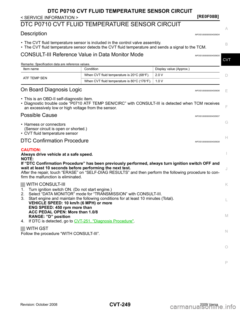
DTC P0710 CVT FLUID TEMPER
ATURE SENSOR CIRCUIT
Description INFOID:0000000004305634
• The CVT fluid temperature sensor is included in the control valve assembly.
• The CVT fluid temperature sensor detects the CV T fluid temperature and sends a signal to the TCM.
CONSULT-III Reference Val ue in Data Monitor Mode INFOID:0000000004305635
Remarks: Specification data are reference values.
On Board Diagnosis Logic INFOID:0000000004305636
• This is an OBD-II self-diagnostic item.
• Diagnostic trouble code “P0710 ATF TEMP SEN/CIRC” with CONSULT-III is detected when TCM receives
an excessively low or high voltage from the sensor.
Possible Cause INFOID:0000000004305637
• Harness or connectors (Sensor circuit is open or shorted.)
• CVT fluid temperature sensor
DTC Confirmation Procedure INFOID:0000000004305638
CAUTION:
Always drive vehicle at a safe speed.
NOTE:
If “DTC Confirmation Procedure” has been previously performed, alw ays turn ignition switch OFF and
wait at least 10 seconds before performing the next test.
After the repair, touch “ERASE” on “SELF-DIAG RESU LTS” and then perform the following procedure to con-
firm the malfunction is eliminated.
WITH CONSULT-III
1. Turn ignition switch ON. (Do not start engine.)
2. Select “DATA MONITOR” mode for “TRANSMISSION” with CONSULT-III.
3. Start engine and maintain the following conditions for at least 10 minutes (Total). VEHICLE SPEED: 10 km/h (6 MPH) or more
ENG SPEED: 450 rpm more than
ACC PEDAL OPEN: More than 1.0/8
RANGE: “D” position
4. If DTC is detected, go to CVT-251, " Diagnosis Procedure " .
WITH GST
Follow the procedure “WITH CONSULT-III”. Item name Condition Display value (Approx.)
ATF TEMP SEN When CVT fluid temperature is 20
°C (68 °F). 2.0 V
When CVT fluid temperature is 80 °C (176 °F). 1.0 V
Page 1207 of 4331

CVT
N
O P
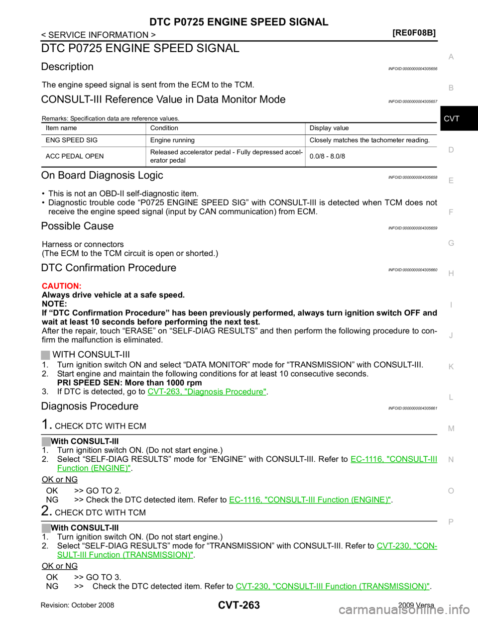
DTC P0725 ENGINE SPEED SIGNAL
Description INFOID:0000000004305656
The engine speed signal is sent from the ECM to the TCM.
CONSULT-III Reference Val ue in Data Monitor Mode INFOID:0000000004305657
Remarks: Specification data are reference values.
On Board Diagnosis Logic INFOID:0000000004305658
• This is not an OBD-II self-diagnostic item.
• Diagnostic trouble code “P0725 ENGINE SPEED SIG” with CONSULT-III is detected when TCM does not
receive the engine speed signal (input by CAN communication) from ECM.
Possible Cause INFOID:0000000004305659
Harness or connectors
(The ECM to the TCM circuit is open or shorted.)
DTC Confirmation Procedure INFOID:0000000004305660
CAUTION:
Always drive vehicle at a safe speed.
NOTE:
If “DTC Confirmation Procedure” has been previously performed, alw ays turn ignition switch OFF and
wait at least 10 seconds before performing the next test.
After the repair, touch “ERASE” on “SELF-DIAG RESU LTS” and then perform the following procedure to con-
firm the malfunction is eliminated.
WITH CONSULT-III
1. Turn ignition switch ON and select “DATA MO NITOR” mode for “TRANSMISSION” with CONSULT-III.
2. Start engine and maintain the following conditions for at least 10 consecutive seconds. PRI SPEED SEN: More than 1000 rpm
3. If DTC is detected, go to CVT-263, " Diagnosis Procedure " .
Diagnosis Procedure INFOID:0000000004305661 CONSULT-III
Function (ENGINE) " .
OK or NG OK >> GO TO 2.
NG >> Check the DTC detected item. Refer to EC-1116, " CONSULT-III Function (ENGINE) " .
CON-
SULT-III Functi
on (TRANSMISSION) " .
OK or NG OK >> GO TO 3.
NG >> Check the DTC detected item. Refer to CVT-230, " CONSULT-III Function (TRANSMISSION) " .
Item name Condition Display value
ENG SPEED SIG Engine running Closely matches the tachometer reading.
ACC PEDAL OPEN Released accelerator pedal - Fully depressed accel-
erator pedal 0.0/8 - 8.0/8
Page 1208 of 4331

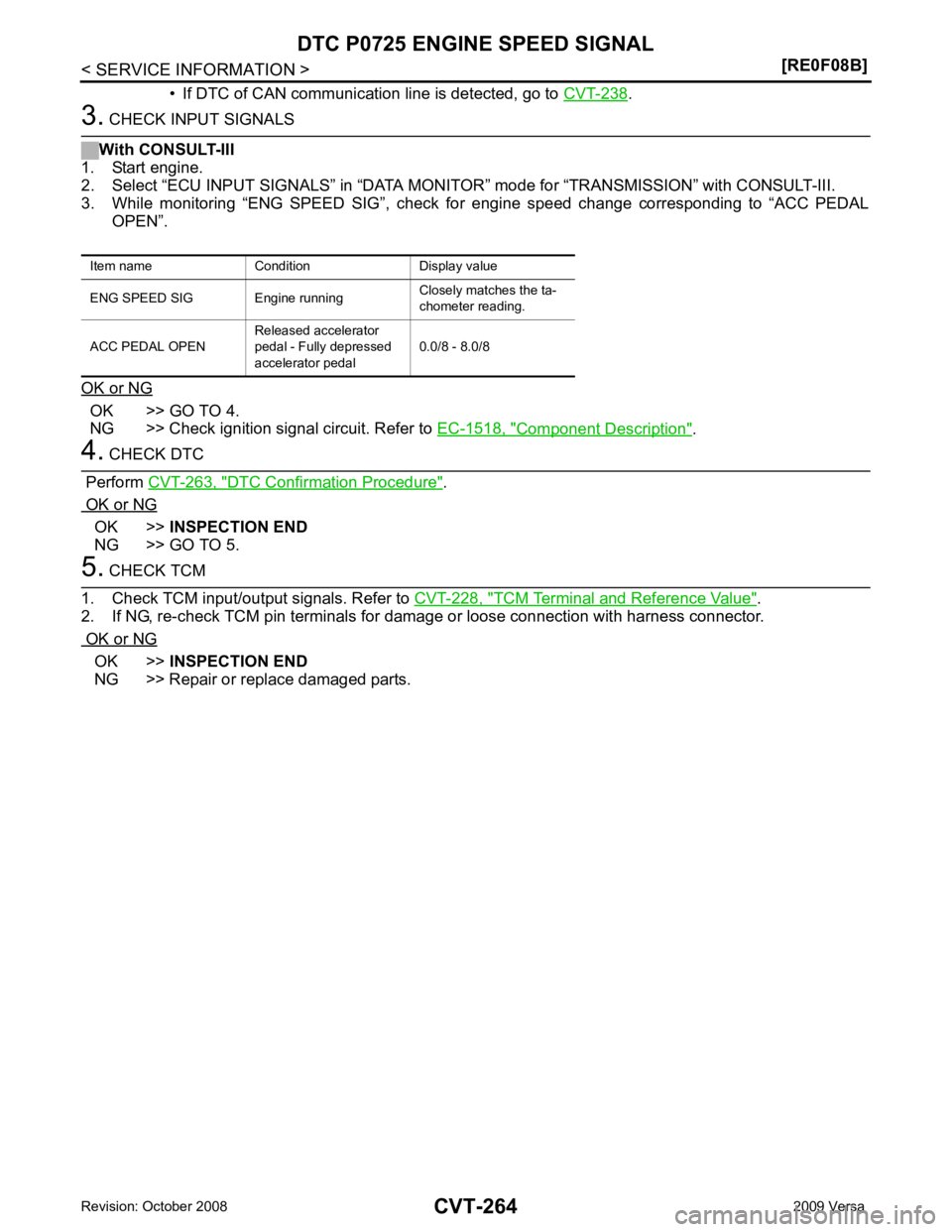
.
OK >> GO TO 4.
NG >> Check ignition signal circuit. Refer to EC-1518, " Component Description " .
DTC Confirmation Procedure " .
OK or NG OK >>
INSPECTION END
NG >> GO TO 5. TCM Terminal and Reference Value " .
2. If NG, re-check TCM pin terminals for damage or loose connection with harness connector.
OK or NG OK >>
INSPECTION END
NG >> Repair or replace damaged parts.
Item name Condition Display value
ENG SPEED SIG Engine running Closely matches the ta-
chometer reading.
ACC PEDAL OPEN Released accelerator
pedal - Fully depressed
accelerator pedal 0.0/8 - 8.0/8
Page 1209 of 4331

CVT
N
O P
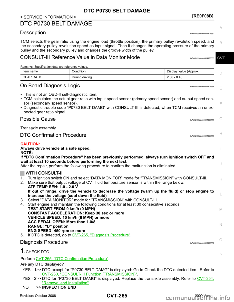
DTC P0730 BELT DAMAGE
Description INFOID:0000000004305662
TCM selects the gear ratio using the engine load (throttle position), the primary pulley revolution speed, and
the secondary pulley revolution speed as input signal. T hen it changes the operating pressure of the primary
pulley and the secondary pulley and changes the groove width of the pulley.
CONSULT-III Reference Val ue in Data Monitor Mode INFOID:0000000004305663
Remarks: Specification data are reference values.
On Board Diagnosis Logic INFOID:0000000004305664
• This is not an OBD-II self-diagnostic item.
• TCM calculates the actual gear ratio with input speed sensor (primary speed sensor) and output speed sen-
sor (secondary speed sensor).
• Diagnostic trouble code “P0730 BELT DAMG” with CONSUL T-III is detected, when TCM receives an unex-
pected gear ratio signal.
Possible Cause INFOID:0000000004305665
Transaxle assembly
DTC Confirmation Procedure INFOID:0000000004305666
CAUTION:
Always drive vehicle at a safe speed.
NOTE:
If “DTC Confirmation Procedure” has been previously performed, alw ays turn ignition switch OFF and
wait at least 10 seconds before performing the next test.
After the repair, perform the following procedure to confirm the malfunction is eliminated.
WITH CONSULT-III
1. Turn ignition switch ON and select “DATA MO NITOR” mode for “TRANSMISSION” with CONSULT-III.
2. Make sure that output voltage of CVT fluid temperature sensor is within the range below.
ATF TEMP SEN: 1.0 - 2.0 V
If out of range, drive the vehicle to decrease the voltage (warm up the fluid) or stop engine to
increase the voltage (c ool down the fluid)
3. Select “DATA MONITOR” mode for “TRANSMISSION” with CONSULT-III.
4. Start engine and maintain the following conditions for at least 30 consecutive seconds.
TEST START FROM 0 km/h (0 MPH)
CONSTANT ACCELERATION: Keep 30 sec or more
VEHICLE SPEED: 10 km/h (6 MPH) or more
ACC PEDAL OPEN: More than 1.0/8
RANGE: “D” position
ENG SPEED: 450 rpm or more
5. If DTC is detected, go to CVT-265, " Diagnosis Procedure " .
Diagnosis Procedure INFOID:0000000004305667DTC Confirmation Procedure " .
Are any DTC displayed? YES - 1>> DTC except for “P0730 BELT DAMG” is displa
yed: Go to Check the DTC detected item. Refer to
CVT-230, " CONSULT-III Function (TRANSMISSION) " .
YES - 2>> DTC for “P0730 BELT DAMG” is displayed: Replace the transaxle assembly. Refer to CVT-354," Removal and Installation " .
NO >> INSPECTION END
Item name Condition Display value (Approx.)
GEAR RATIO During driving 2.56 - 0.43