Page 1215 of 4331

CVT
N
O P
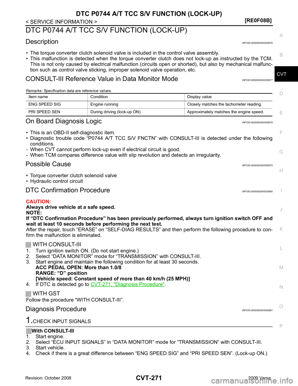
DTC P0744 A/T TCC S/V FUNCTION (LOCK-UP)
Description INFOID:0000000004305676
• The torque converter clutch solenoid valve is included in the control valve assembly.
• This malfunction is detected when the torque converter clutch does not lock-up as instructed by the TCM.
This is not only caused by electrical malfunction (cir cuits open or shorted), but also by mechanical malfunc-
tion such as control valve sticking, improper solenoid valve operation, etc.
CONSULT-III Reference Val ue in Data Monitor Mode INFOID:0000000004305677
Remarks: Specification data are reference values.
On Board Diagnosis Logic INFOID:0000000004305678
• This is an OBD-II self-diagnostic item.
• Diagnostic trouble code “P0744 A/T TCC S/V FNCTN” wit h CONSULT-III is detected under the following
conditions.
- When CVT cannot perform lock-up even if electrical circuit is good.
- When TCM compares difference value with slip revolution and detects an irregularity.
Possible Cause INFOID:0000000004305679
• Torque converter clutch solenoid valve
• Hydraulic control circuit
DTC Confirmation Procedure INFOID:0000000004305680
CAUTION:
Always drive vehicle at a safe speed.
NOTE:
If “DTC Confirmation Procedure” has been previously performed, alw ays turn ignition switch OFF and
wait at least 10 seconds before performing the next test.
After the repair, touch “ERASE” on “SELF-DIAG RESU LTS” and then perform the following procedure to con-
firm the malfunction is eliminated.
WITH CONSULT-III
1. Turn ignition switch ON. (Do not start engine.)
2. Select “DATA MONITOR” mode for “TRANSMISSION” with CONSULT-III.
3. Start engine and maintain the following condition for at least 30 seconds.
ACC PEDAL OPEN: More than 1.0/8
RANGE: “D” position
[Vehicle speed: Constant speed of more than 40 km/h (25 MPH)]
4. If DTC is detected go to CVT-271, " Diagnosis Procedure " .
WITH GST
Follow the procedure “WITH CONSULT-III”.
Diagnosis Procedure INFOID:0000000004305681
Page 1216 of 4331

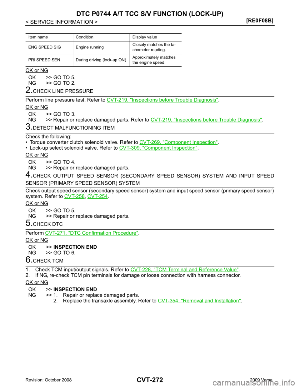
OK >> GO TO 5.
NG >> GO TO 2. Inspections before Trouble Diagnosis " .
OK or NG OK >> GO TO 3.
NG >> Repair or replace damaged parts. Refer to CVT-219, " Inspections before Trouble Diagnosis " .
Component Inspection " .
• Lock-up select solenoid valve. Refer to CVT-309, " Component Inspection " .
OK or NG OK >> GO TO 4.
NG >> Repair or replace damaged parts.
4. CHECK OUTPUT SPEED SENSOR (SECONDARY SPEED SENSOR) SYSTEM AND INPUT SPEED ,
CVT-254 .
OK or NG OK >> GO TO 5.
NG >> Repair or replace damaged parts. DTC Confirmation Procedure " .
OK or NG OK >>
INSPECTION END
NG >> GO TO 6. TCM Terminal and Reference Value " .
2. If NG, re-check TCM pin terminals for damage or loose connection with harness connector.
OK or NG OK >>
INSPECTION END
NG >> 1. Repair or replace damaged parts. 2. Replace the transaxle assembly. Refer to CVT-354, " Removal and Installation " .
Item name Condition Display value
ENG SPEED SIG Eng ine runningClosely matches the ta-
chometer reading.
PRI SPEED SEN During driving (lock-up ON) Approximately matches
the engine speed.
Page 1217 of 4331

CVT
N
O P
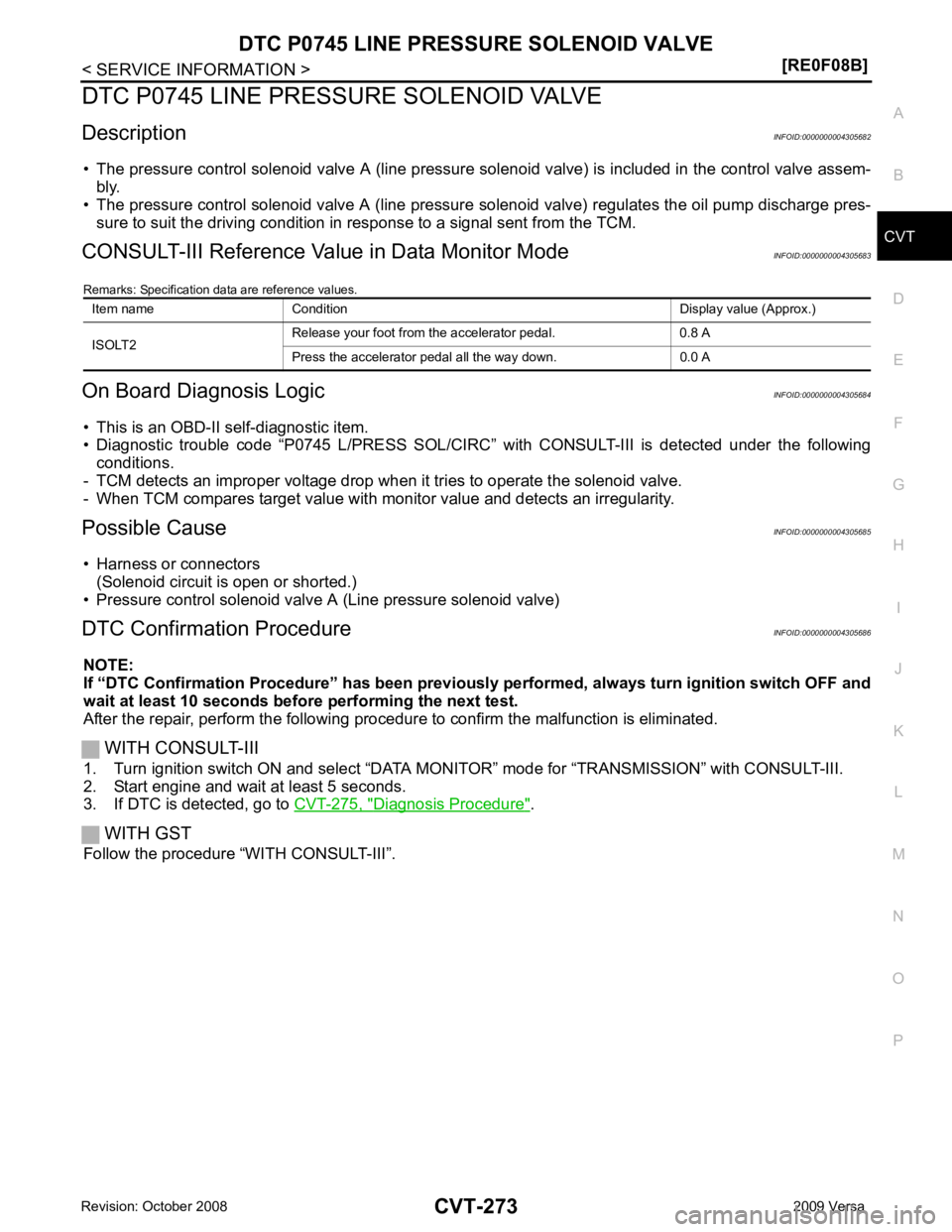
DTC P0745 LINE PRESSURE SOLENOID VALVE
Description INFOID:0000000004305682
• The pressure control solenoid valve A (line pressure solenoid valve) is included in the control valve assem- bly.
• The pressure control solenoid valve A (line pressure solenoid valve) regulates the oil pump discharge pres-
sure to suit the driving condition in response to a signal sent from the TCM.
CONSULT-III Reference Val ue in Data Monitor Mode INFOID:0000000004305683
Remarks: Specification data are reference values.
On Board Diagnosis Logic INFOID:0000000004305684
• This is an OBD-II self-diagnostic item.
• Diagnostic trouble code “P0745 L/PRESS SOL/CIRC” with CONSULT-III is detected under the following
conditions.
- TCM detects an improper voltage drop when it tries to operate the solenoid valve.
- When TCM compares target value with monitor value and detects an irregularity.
Possible Cause INFOID:0000000004305685
• Harness or connectors (Solenoid circuit is open or shorted.)
• Pressure control solenoid valve A (Line pressure solenoid valve)
DTC Confirmation Procedure INFOID:0000000004305686
NOTE:
If “DTC Confirmation Procedure” has been previously performed, alw ays turn ignition switch OFF and
wait at least 10 seconds before performing the next test.
After the repair, perform the following procedure to confirm the malfunction is eliminated.
WITH CONSULT-III
1. Turn ignition switch ON and select “DATA MO NITOR” mode for “TRANSMISSION” with CONSULT-III.
2. Start engine and wait at least 5 seconds.
3. If DTC is detected, go to CVT-275, " Diagnosis Procedure " .
WITH GST
Follow the procedure “WITH CONSULT-III”. Item name Condition Display value (Approx.)
ISOLT2 Release your foot from the accelerator pedal. 0.8 A
Press the accelerator pedal all the way down. 0.0 A
Page 1222 of 4331
Diagnosis Procedure " .
WITH GST
Follow the procedure “WITH CONSULT-III”.
Diagnosis Procedure INFOID:0000000004305695Inspections before Trouble Diagnosis " .
OK or NG OK >> GO TO 2.
NG >> Repair or replace damaged parts. Refer to CVT-219, " Inspections before Trouble Diagnosis " .
Item name Condition Display value (Approx.)
PRI PRESS “N” position idle 0.4 MPa
Page 1225 of 4331
CVT
N
O P
OK or NG OK >> GO TO 5.
NG >> GO TO 2. Inspections before Trouble Diagnosis " .
OK or NG OK >> GO TO 3.
NG >> Repair or replace damaged parts. Refer to CVT-219, " Inspections before Trouble Diagnosis " .
Component
Inspection " .
• Pressure control solenoid valve A (Line pressure solenoid valve). Refer to CVT-276, " Component Inspec-
tion " .
OK or NG OK >> GO TO 4.
NG >> Repair or replace damaged parts.
4. CHECK TRANSMISSION FLUID PRESSURE SENSOR A (SECONDARY PRESSURE SENSOR) SYS- .
OK or NG OK >> GO TO 5.
NG >> Repair or replace damaged parts. Wiring Diagram - CVT - POWER " .
• The TCM pin terminals for damage or loose connection with harness connector.
OK or NG OK >> GO TO 6.
NG >> Repair or replace damaged parts. DTC Confirmation Procedure " .
OK or NG OK >>
INSPECTION END
NG >> Replace the transaxle assembly. Refer to CVT-354, " Removal and Installation " .
Item name Condition Display value (Approx.)
SEC PRESS “N” position idle 0.8 MPa
Page 1231 of 4331

CVT
N
O P
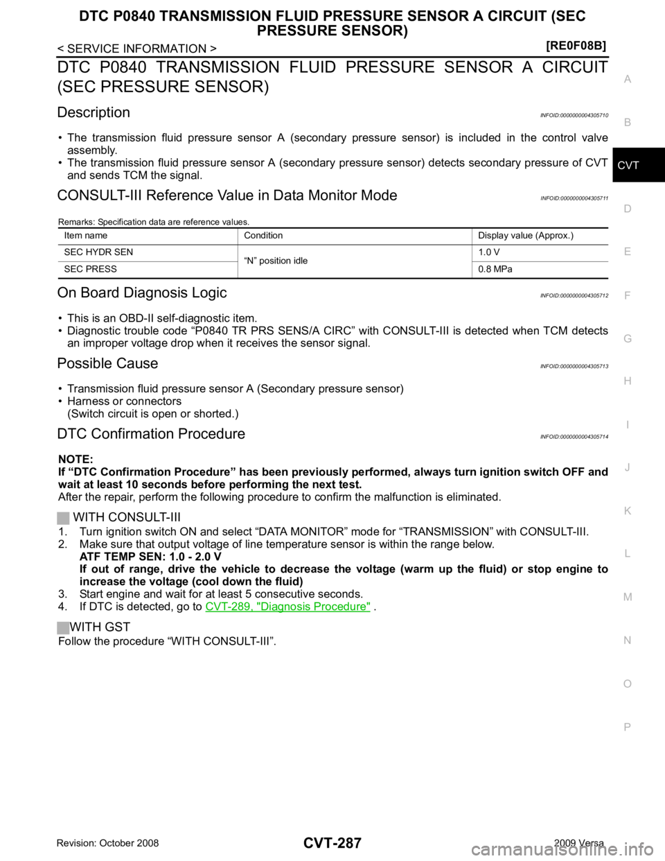
DTC P0840 TRANSMISSION FLUID
PRESSURE SENSOR A CIRCUIT
(SEC PRESSURE SENSOR)
Description INFOID:0000000004305710
• The transmission fluid pressure sensor A (secondary pressure sensor) is included in the control valve
assembly.
• The transmission fluid pressure sensor A (secondary pressure sensor) detects secondary pressure of CVT
and sends TCM the signal.
CONSULT-III Reference Val ue in Data Monitor Mode INFOID:0000000004305711
Remarks: Specification data are reference values.
On Board Diagnosis Logic INFOID:0000000004305712
• This is an OBD-II self-diagnostic item.
• Diagnostic trouble code “P0840 TR PRS SENS/A CIRC” with CONSULT-III is detected when TCM detects
an improper voltage drop when it receives the sensor signal.
Possible Cause INFOID:0000000004305713
• Transmission fluid pressure sensor A (Secondary pressure sensor)
• Harness or connectors (Switch circuit is open or shorted.)
DTC Confirmation Procedure INFOID:0000000004305714
NOTE:
If “DTC Confirmation Procedure” has been previously performed, alw ays turn ignition switch OFF and
wait at least 10 seconds before performing the next test.
After the repair, perform the following procedure to confirm the malfunction is eliminated.
WITH CONSULT-III
1. Turn ignition switch ON and select “DATA MO NITOR” mode for “TRANSMISSION” with CONSULT-III.
2. Make sure that output voltage of line te mperature sensor is within the range below.
ATF TEMP SEN: 1.0 - 2.0 V
If out of range, drive the vehicle to decrease the voltage (warm up the fluid) or stop engine to
increase the voltage (c ool down the fluid)
3. Start engine and wait for at least 5 consecutive seconds.
4. If DTC is detected, go to CVT-289, " Diagnosis Procedure " .
WITH GST
Follow the procedure “WITH CONSULT-III”. Item name Condition Display value (Approx.)
SEC HYDR SEN “N” position idle 1.0 V
SEC PRESS 0.8 MPa
Page 1235 of 4331

CVT
N
O P
DTC P0841 PRESSURE SENSOR FUNCTION
Description INFOID:0000000004305717
Using the engine load (throttle position), the primary pulley revolution speed, and the secondary pulley revolu-
tion speed as input signal, TCM changes the operating pr essure of the primary pulley and the secondary pul-
ley and changes the groove width of the pulley to control the gear ratio.
CONSULT-III Reference Val ue in Data Monitor Mode INFOID:0000000004305718
Remarks: Specification data are reference values.
On Board Diagnosis Logic INFOID:0000000004305719
• This is not an OBD-II self-diagnostic item.
• Diagnostic trouble code “P0841 PRESS SEN/FNCTN” with CONSULT-III is detected when secondary fluid
pressure is too high compared with the commanded value while driving.
Possible Cause INFOID:0000000004305720
• Transmission fluid pressure sensor A (Secondary pressure sensor)
• Harness or connectors
(Sensor circuit is open or shorted.)
DTC Confirmation Procedure INFOID:0000000004305721
CAUTION:
Always drive vehicle at a safe speed.
NOTE:
If “DTC Confirmation Procedure” has been previously performed, alw ays turn ignition switch OFF and
wait at least 10 seconds before performing the next test.
After the repair, perform the following procedure to confirm the malfunction is eliminated.
WITH CONSULT-III
1. Turn ignition switch ON and select “DATA MO NITOR” mode for “TRANSMISSION” with CONSULT-III.
2. Start engine and maintain the following conditions for at least 12 consecutive seconds. VEHICLE SPEED: 40 km/h (25 MPH) More than
RANGE: “D” position
3. If DTC is detected, go to CVT-291, " Diagnosis Procedure " .
Diagnosis Procedure INFOID:0000000004305722CONSULT-III Function (TRANSMISSION) " .
Is any malfunction of the “ U1000 CAN COMM CIRCUIT ” indicated?
YES >> Check CAN communication line. Refer to
CVT-238 .
NO >> GO TO 2.
Page 1236 of 4331
OK >> GO TO 6.
NG >> GO TO 3. Inspections before Trouble Diagnosis " .
OK or NG OK >> GO TO 4.
NG >> Repair or replace damaged parts. Refer to CVT-219, " Inspections before Trouble Diagnosis " .
4. CHECK TRANSMISSION FLUID PRESSURE SENS OR A (SECONDARY PRESSURE SENSOR) SYS- .
OK or NG OK >> GO TO 5.
NG >> Repair or replace damaged parts. Component Inspec-
tion " .
• Step motor. Refer to CVT-314, " Component Inspection " .
OK or NG6 OK >> GO TO 6.
NG >> Repair or replace damaged parts. DTC Confirmation Procedure " .
OK or NG OK >>
INSPECTION END
NG >> Replace TCM or transaxle assembly. Refer to CVT-354, " Removal and Installation " .
Item name Condition Display value (Approx.)
PRI HYDR SEN “N” position idle 0.7 V
SEC HYDR SEN 1.0 V Name Connector Terminal Condition
Voltage
(Approx.)
Transmission fluid
pressure sensor A
(Secondary pres-
sure sensor) E32 37 - Ground “N” position idle 1.0 V B